|
|
Post by Roger on Jan 30, 2024 21:00:24 GMT
Hi Roger, I would be most interested in you trying the ‘FSD’ drawn phos bronze tube as an experiment. Cheers, Julian Hi Julian, I might try that in a bit, but the wall thickness of those tubes is probably too thick to work in this size of gauge with that much travel required. |
|
jma1009
Elder Statesman
  
Posts: 5,919
|
Post by jma1009 on Jan 31, 2024 0:49:07 GMT
Hi Roger,
I understood that the ‘FSD’ drawn phos bronze tube was as used by Freddie Dinnis before rolling and forming.
Worth a try?
(I used the Roy Amesbury method). It was only some years later I was given a few lengths of the FSD drawn tube.
Cheers,
Julian
|
|
|
|
Post by Roger on Jan 31, 2024 10:46:31 GMT
Hi Roger, I understood that the ‘FSD’ drawn phos bronze tube was as used by Freddie Dinnis before rolling and forming. Worth a try? (I used the Roy Amesbury method). It was only some years later I was given a few lengths of the FSD drawn tube. Cheers, Julian Hi Julian, I'm not sure I understand what you're saying. Do you mean that the drawn tube needs to be drawn further? I'm measuring the ones you sent me as having a 0.14mm wall thickness, and that seems miles too thick and rigid to me. I'm using 0.05mm thick sheet, so that's about a third of the thickness. |
|
jem
Elder Statesman
  
Posts: 1,075
|
Post by jem on Jan 31, 2024 17:26:34 GMT
If you filled them with solder, how would you ever get it out again?
best wishes
Jem
|
|
jma1009
Elder Statesman
  
Posts: 5,919
|
Post by jma1009 on Jan 31, 2024 23:12:15 GMT
Hi Roger,
I must apologise.
I was told that the FSD drawn phos bronze tube of oval section was that used by Freddie Dinnis, and never myself measured the thickness. I assumed it was the final size. That clearly cannot be correct as you state it is too thick.
I can’t remember tonight without checking that the Roy Amesbury method was say 4 thou thickness for a pressure gauge, and less for a vacuum gauge. It never crossed my mind to check the FSD drawn tube I and many others had, and that it was not the final drawn tube but of partly drawn tube!
So, apologies again.
Cheers,
Julian
|
|
|
|
Post by flyingfox on Feb 1, 2024 8:14:56 GMT
Julian. I thought he turned down the solid drawn tube, on a mandrel, to the thickness he wanted.
Or is that old age creeping in?
Regards
Brian B
|
|
|
|
Post by Roger on Feb 1, 2024 9:51:17 GMT
If you filled them with solder, how would you ever get it out again? best wishes Jem Hi Jem, I think that would be possible by using compressed air when it's molten. It might take a few attempts, but I think you'd get most of it out. |
|
|
|
Post by Roger on Feb 1, 2024 11:04:23 GMT
Hi Roger, I must apologise. I was told that the FSD drawn phos bronze tube of oval section was that used by Freddie Dinnis, and never myself measured the thickness. I assumed it was the final size. That clearly cannot be correct as you state it is too thick. I can’t remember tonight without checking that the Roy Amesbury method was say 4 thou thickness for a pressure gauge, and less for a vacuum gauge. It never crossed my mind to check the FSD drawn tube I and many others had, and that it was not the final drawn tube but of partly drawn tube! So, apologies again. Cheers, Julian Hi Julian, Those figures sound plausible, the thinner the better if you need a lot of travel. The oval tube could be made round and put on a mandrel. It's probably just as easy to make them from solid though. It would be interesting to see if the tube could be drawn down any more. It's quite a lot of work to make the dies though. I'll see how this current method plays out, there are still a lot of things to try. |
|
|
|
Post by Roger on Feb 1, 2024 22:43:33 GMT
Here's the new body with the curved support for the inside of the Bourdon tube.  PXL_20240129_180335452 PXL_20240129_180335452 by Billy Roberts, on Flickr These are M1 tapped holes that are used from both sides. One holds the body to the case, the other holds the front gear plate on.  PXL_20240129_183239900 PXL_20240129_183239900 by Billy Roberts, on Flickr The entry hole and location is 1.2mm to hold the inlet fitting in the right place for Silver Soldering 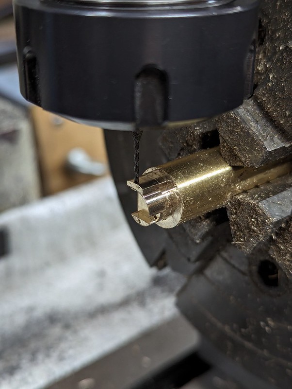 PXL_20240129_184337163 PXL_20240129_184337163 by Billy Roberts, on Flickr a 0.8mm PCB burr is used to cut the slot and hole for the Bourdon tube.  PXL_20240129_185649368 PXL_20240129_185649368 by Billy Roberts, on Flickr This time I decided to press the joint in the Bourdon tubes lightly together while Silver Soldering them. Here's a piece of Titanium sheet, folded at both ends to give the open end more rigidity where it's going to press against the tube. I've used nail varnish for all of the Silver Solder masking. 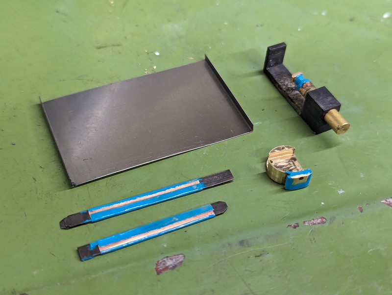 PXL_20240201_090027230 PXL_20240201_090027230 by Billy Roberts, on Flickr There are not changes that affect the fixture, so that's the same as before. 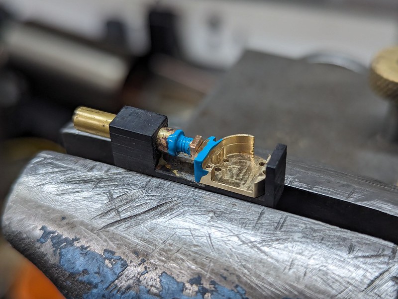 PXL_20240201_090755292 PXL_20240201_090755292 by Billy Roberts, on Flickr You can see the 'U' shaped piece of 0.5mm Silver Solder wire hooked over ready for heating.  PXL_20240201_095803854 PXL_20240201_095803854 by Billy Roberts, on Flickr 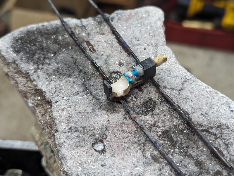 PXL_20240201_100732902 PXL_20240201_100732902 by Billy Roberts, on Flickr That looks like it came out ok. Note that this is the direction that the flame was applied from ie to the left and trying to avoid overheating that thin section.  PXL_20240201_101131489 PXL_20240201_101131489 by Billy Roberts, on Flickr Here's the setup for the Bourdon tube, with the folded end of the Titanium sheet pressing down just behind the joint on the overlapping piece. i had to leave the shims in place else it would have collapsed. The two shims are Titanium this time. There are just three short lengths of Silver Solder. I just need enough to make the joint and nothing more. Extra makes it stiffer, and I need to keep it as flexible as possible. 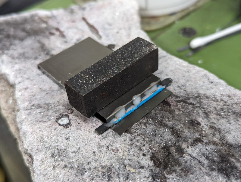 PXL_20240201_103542798 PXL_20240201_103542798 by Billy Roberts, on Flickr The nail varnish works a treat, I'm going to use that from here on in. I think it works much better than Tippex.  PXL_20240201_104135581 PXL_20240201_104135581 by Billy Roberts, on Flickr Ok, the end of the Bourdon tube didn't quite Solder up, I'll have to heat that up again. The body came out ok though. 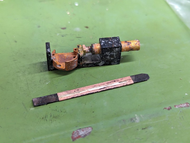 PXL_20240201_111702971 PXL_20240201_111702971 by Billy Roberts, on Flickr  PXL_20240201_172255222 PXL_20240201_172255222 by Billy Roberts, on Flickr This is the second one,which came out better...  PXL_20240201_193950098 PXL_20240201_193950098 by Billy Roberts, on Flickr ... so I decided to carry on with that one. Here are the Steel shims to support it during rolling. The shim was marked out using the Height Gauge and then cut with scissors. They were pulled through some doubled up emery paper to remove the burrs.  Six pieces fitted, and this is the result of the first gentle bend...  PXL_20240201_200739358 PXL_20240201_200739358 by Billy Roberts, on Flickr ... which was then annealed and bent again... 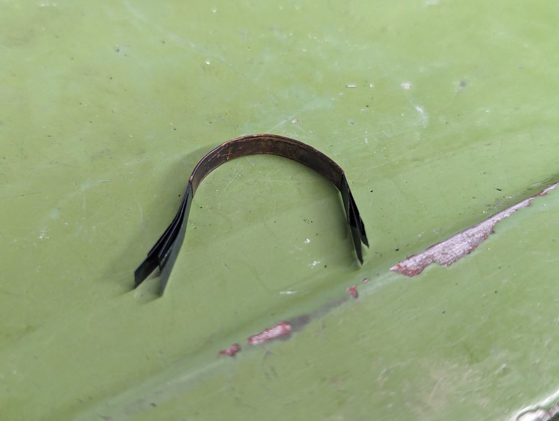 PXL_20240201_201346847 PXL_20240201_201346847 by Billy Roberts, on Flickr ... then Annealed and bent again... 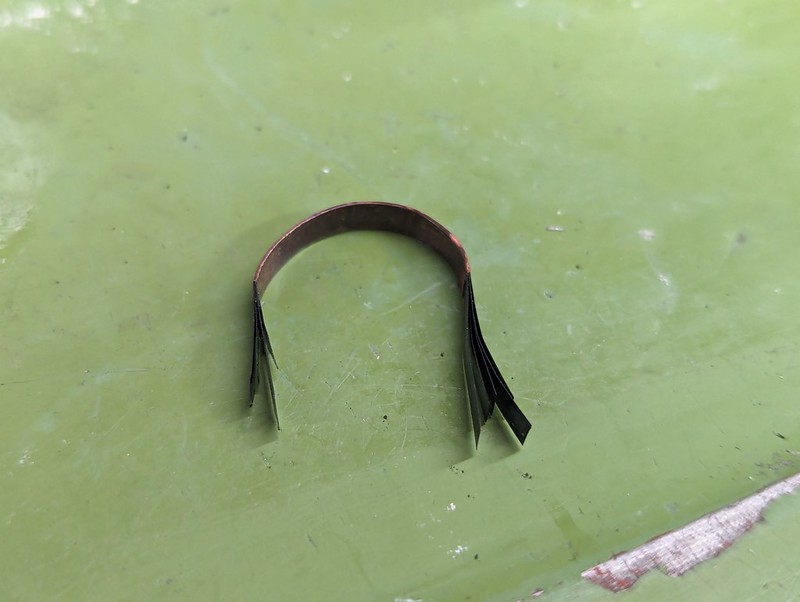 PXL_20240201_203150874 PXL_20240201_203150874 by Billy Roberts, on Flickr ... and again...  PXL_20240201_211949051 PXL_20240201_211949051 by Billy Roberts, on Flickr ... until it was a tight enough radius. The annealing was done very gingerly from the inside, just enough to see it briefly flash a very dull Red. It was turned over and done again to make sure that both edges were annealed. 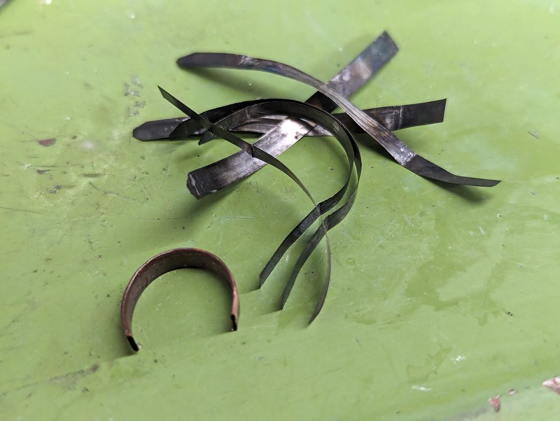 PXL_20240201_212421407 PXL_20240201_212421407 by Billy Roberts, on Flickr The rollers make easy work of flattening the small ripples caused by each bending, but only because the tube is annealed. This is definitely the best one I've made so far, so hopefully it will work out this time. |
|
jma1009
Elder Statesman
  
Posts: 5,919
|
Post by jma1009 on Feb 1, 2024 23:38:27 GMT
Hi Roger,
(And I must apologise for what now turns out to be irrelevant distractions to your thread which I always follow closely).
Have you considered the Roy Amesbury method of a in your case beryllium copper drilled and reamed to put onto a mandrel to turn down? (This answers Brian’s query I think as to method)?
That might avoid the silver soldering of beryllium copper shim.
I don’t know how you remove the effects of annealing other than the rolling of the bourdon tube to achieve a stable springing of the bourdon tube. Do you have an opinion on this please? Do you consider the rolling of the tube to achieve this?
Is there merit in the Roy Amesbury method that might be worth considering? (Roy used Sifbronze).
Cheers,
Julian
|
|
|
|
Post by Roger on Feb 5, 2024 22:16:47 GMT
I made a nice thin section Bourdon tube, but that turned out to be too thin, fragile and prone to becoming blocked with Solder when trying to attach it to the body. So here's a much thicker one that returns to using three Titanium shims. I've used the same method to press the joint together, so this should have a more flexible side where the joint it this time. Again, the Nail Varnish seems to have done a reasonable job keeping the Silver Solder in place, and this is how it looks straight out of the Ultrasonic tank.  PXL_20240205_203821657 PXL_20240205_203821657 by Billy Roberts, on Flickr And this is how it looks after cleaning up with needle files.  PXL_20240205_205557608 PXL_20240205_205557608 by Billy Roberts, on Flickr As you can see, this has quite a large cross section.  PXL_20240205_205655528 PXL_20240205_205655528 by Billy Roberts, on Flickr Here it is again, but this time filled with about 14 Steel shims ready for rolling.  PXL_20240205_211434925 PXL_20240205_211434925 by Billy Roberts, on Flickr Straight away I realised that I'd rolled it the wrong way, with the joint on the inside. Doh! I decided to just go with it, since I haven't made one that way round yet, and it will be interesting to see what happens.  PXL_20240205_212438734 PXL_20240205_212438734 by Billy Roberts, on Flickr I was very gentle with each bend, annealing 6 times in total to get it all the way around. 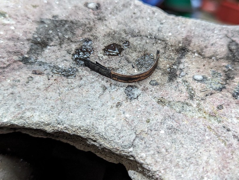 PXL_20240205_212940181 PXL_20240205_212940181 by Billy Roberts, on Flickr 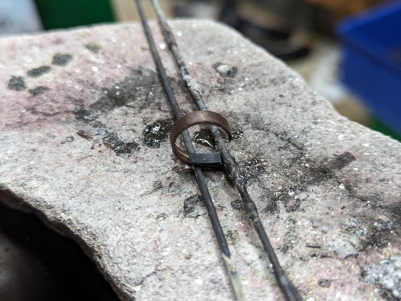 PXL_20240205_213912059 PXL_20240205_213912059 by Billy Roberts, on Flickr This appears to be ok, but I can't pull the shims out, they're too oxidised. So, plan B is to dissolve them partially or completely with Citric Acid. These are Steel shims, not Stainless Steel. We'll see how that goes tomorrow when it's had all night to think about it. 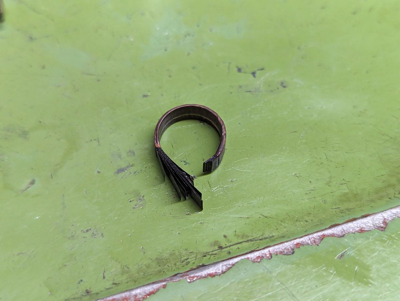 PXL_20240205_214237876 PXL_20240205_214237876 by Billy Roberts, on Flickr |
|
|
|
Post by Roger on Feb 15, 2024 18:26:19 GMT
Ok, one more time round the design loop for the Pressure Gauge, because the motion of the end of the Bourdon Tube tends to be much more in the up/down direction than side to side. This version uses a much smaller quadrant gear which allows the pivot point to be much lower, and this time to the right. Doing that allows the full motion of the tube be be mostly vertical. The quadrant can much more easily transfer that motion to the small gear with it in that orientation. I'm much happier with this setup, but it is going to require a new gear cutter because the gear is a between the two sizes I've got them for. 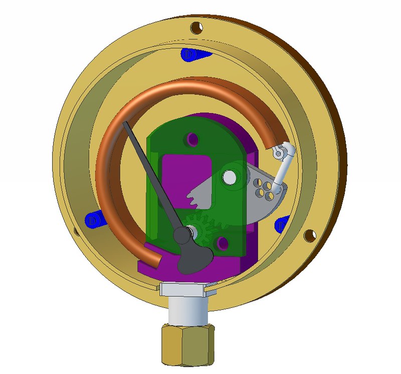 Pressure gauge assembly Pressure gauge assembly by Billy Roberts, on Flickr Hopefully I'll have time to make this shortly. |
|
peteh
Statesman
  Still making mistakes!
Posts: 760
|
Post by peteh on Feb 16, 2024 0:51:13 GMT
I love your design processes Roger and applaud you for taking the time to show us all - many thanks
|
|
|
|
Post by Roger on Feb 16, 2024 22:44:30 GMT
You are most welcome Pete. I enjoy the harder problems the most, it's a challenge. Here's the new single point cutter for the 42 tooth gear, again being machined from 3mm wide x 1mm thick HSS. I'm using a 1mm PCB Carbide burr, setting the tip to zero at the top of the stock, but setting the machining operations to cut to 6mm deep since there's a full 6mm of burr and I want to keep the deflection to a minimum. 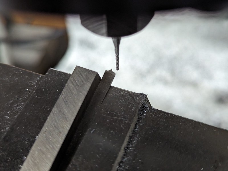 PXL_20240216_204559303 PXL_20240216_204559303 by Billy Roberts, on Flickr I'm using 9 separate operations to create the shape, with the tool paths all on top of each other in the RH pane. The Red traces are high speed moves with the tool up. The blue traces are the cutter centre line paths. The strategy is to climb mill and fully rough and finish the LH side and top first. That's because the stock on the RH side is there to support the cut. Notice that the profile is finished and then repeated at a different level on the burr so it's sharp for the final spring cut. The RH side is more troublesome because the point of the profile is so slender. That's why it's roughed only part of the way there, and then finished very gingerly using a conventional cutting direction ie from the top to the bottom RH edge. That's so the thin tip doesn't get grabbed and broken by a Climb milling cut. It's all done very slowly, so this took about 5 hours. It could have been done quicker, but I've been busy on another job so there's no need to rush.  Form tool machining operations Form tool machining operations by Billy Roberts, on Flickr |
|
|
|
Post by Roger on Feb 18, 2024 22:31:15 GMT
This is the body of the latest Pressure Gauge version. 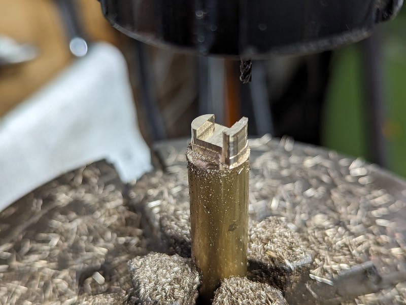 PXL_20240218_141820749 PXL_20240218_141820749 by Billy Roberts, on Flickr Using the 4th axis allows the piece to be turned on its side without losing the angular position. Here I'm setting the 1mm PCB burr to the top of the stock, the Z-axis is then set to the radius so the centre of rotation is the zero point for the tip of the tool. 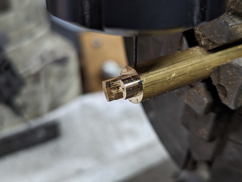 PXL_20240218_145221354 PXL_20240218_145221354 by Billy Roberts, on Flickr The Triad in the CAM setup was turned through 24 degrees to bring this cut vertical, and the 4th axis was commanded to go there too. The full witdh of the slot was cut first, followed by the deeper pocket needed to intersect with the inlet hole. 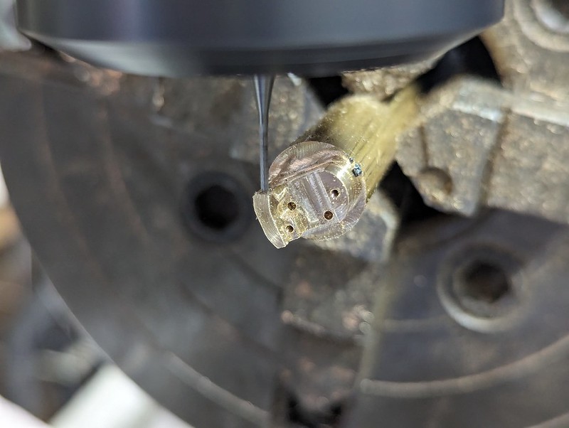 PXL_20240218_145334958 PXL_20240218_145334958 by Billy Roberts, on Flickr The Large gear quadrant was roughed out on the lathe, then profiled on the Mill...  PXL_20240218_210430073 PXL_20240218_210430073 by Billy Roberts, on Flickr ... and the 0.55mm wire holes added. 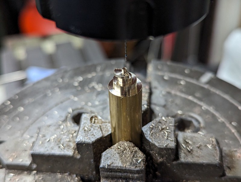 PXL_20240218_211209702 PXL_20240218_211209702 by Billy Roberts, on Flickr Again, the 4th axis was turned over and the single point gear cutting tool was set up. 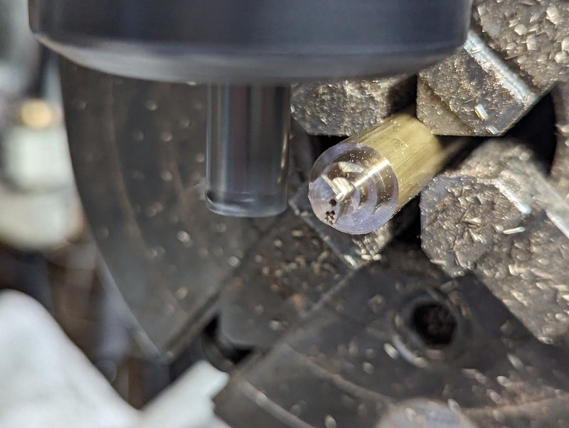 PXL_20240218_214931375 PXL_20240218_214931375 by Billy Roberts, on Flickr I should have allowed a bit more clearance for the tool, but it looks like it cut the teeth ok. 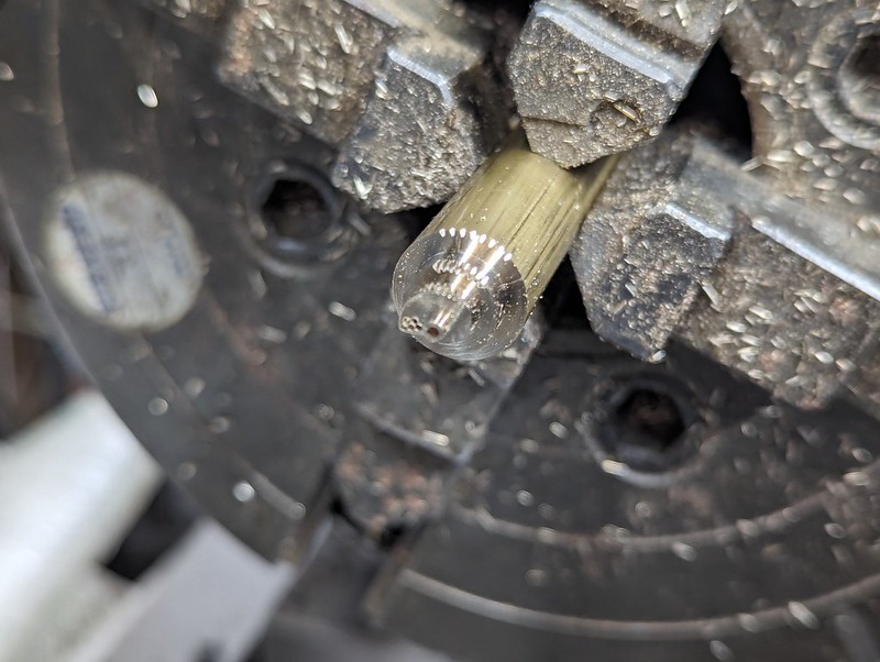 PXL_20240218_221011900 PXL_20240218_221011900 by Billy Roberts, on Flickr I cleaned the face of the gear up with a Daimond needle file and ran the program again to make sure any burrs I'm pushed into the gaps between the teeth were removed. Both of those were then parted off to length. 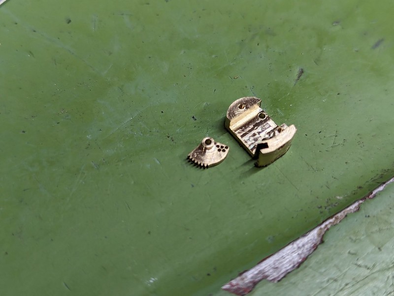 PXL_20240218_221759725 PXL_20240218_221759725 by Billy Roberts, on Flickr |
|
|
|
Post by Roger on Feb 20, 2024 21:42:48 GMT
I managed a little more progress on the Gauge today. The inlet fitting was Silver Soldered to the body, and the cover plate made. This time, the hole through to the Bourdon Tube is blocked with Silver Solder, so that's going to need attention.  PXL_20240220_213607392 PXL_20240220_213607392 by Billy Roberts, on Flickr |
|
|
|
Post by Roger on Mar 5, 2024 22:17:01 GMT
Soldering the Bourdon tube onto the body is a pain in the neck because it's hard to hold it in the correct position while you do that. Here's a little fixture that's attached to the body to make that a bit easier. 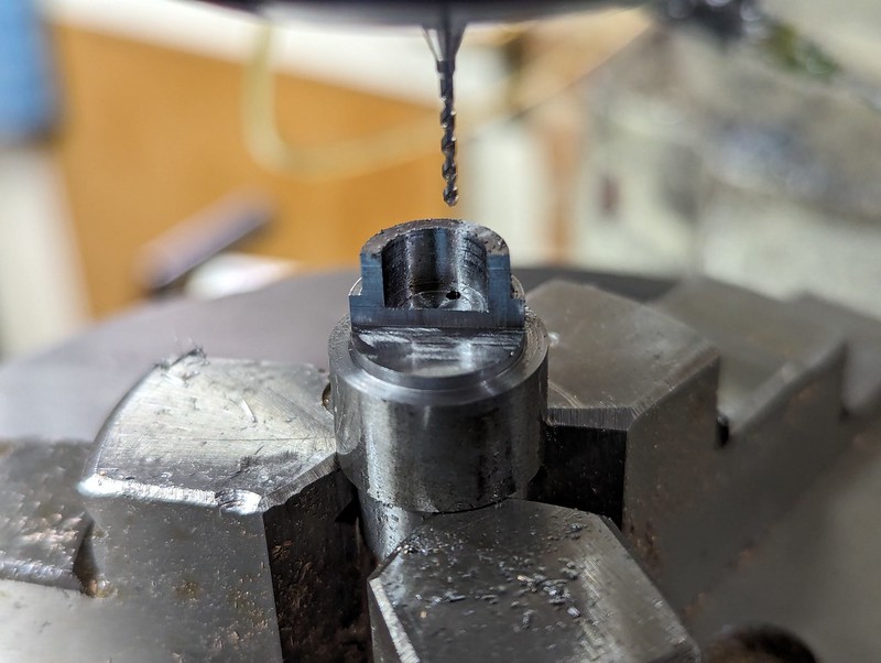 PXL_20240301_120211403 PXL_20240301_120211403 by Billy Roberts, on Flickr I've just wrapped a short length of Solder around the joint, added some plumbers flux and heated it with a Hot Air Gun. 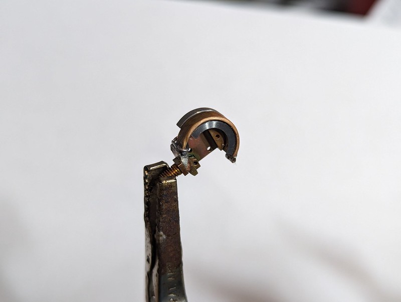 PXL_20240301_184129571 PXL_20240301_184129571 by Billy Roberts, on Flickr That worked really well.  PXL_20240302_120026076 PXL_20240302_120026076 by Billy Roberts, on Flickr However, I'm finding that the tube is now too flexible and ends up getting blown out much too straight, not coming back to the smaller radius afterwards. Obviously it's soft after Silver Soldering, so there's the issue of how to work harden it. Anyway, this isn't going to work as it is, so I'll make another one from the slightly thicker material and also roll it to a slightly smaller radius to start with. It may be necessary to flex it back and forth when I get it to the final diameter with the formers still inside to that it doesn't collapse while doing that. It's nearly there, but needs a few more tweaks before it's going to be viable. Silver Soldering the joint in the more subtle way has made the whole tube much more flexible because there's so much less Silver Solder on the joint. I'll get there in the end, it's just a matter of getting the proportions and the method right. |
|
|
|
Post by chris vine on Mar 5, 2024 22:30:47 GMT
Hi Roger,
Great progress!
On the subject of annealing and then finding that it's too soft: Are you sure you need to anneal it at all? I would have thought that something as thin and small as that would bend to the required radius without any annealing.
I am thinking of small copper tubes, eg the 1/16" copper pipes which I think we have both used. No need to anneal them to bend into tighter radii than you are doing for the bourdon tube.
If it wasn't annealed, I think the result would be more predictable for you...
Chris.
|
|
|
|
Post by Roger on Mar 6, 2024 11:58:28 GMT
Hi Roger, Great progress! On the subject of annealing and then finding that it's too soft: Are you sure you need to anneal it at all? I would have thought that something as thin and small as that would bend to the required radius without any annealing. I am thinking of small copper tubes, eg the 1/16" copper pipes which I think we have both used. No need to anneal them to bend into tighter radii than you are doing for the bourdon tube. If it wasn't annealed, I think the result would be more predictable for you... Chris. Hi Chris, I tried it without annealing, and it just cracks on the edges. It's thin, so it tends to tear. There may be a middle ground where the initial couple of bends to get it half way there use annealing, then finish off without. |
|
|
|
Post by Roger on Mar 23, 2024 11:13:46 GMT
Slow progress due to being so busy with other matters, but I have finally managed to find a way to create the image I need for the Pressure Gauge Dial. I originally drew it in Alibre Design, but there was no way to create an output that would be suitable for printing. What's needed is Vector Graphics so that the image can be output without becoming pixellated. There are plenty of these CAD packages, but they are mostly paid ones or free trials with no output. However, Inkscape is a capable package that is genuinely free. There are also quite a few tutorials on YouTube which help enormously. Initially, I didn't think I've be able to do it, because it's so unintuitive and painful to use when you're not familiar with it. There are so many controls, 99% of which I don't need to know about, but I didn't know which ones were necessary. Anyway, I've figured out how to place objects relative to each other, define line thicknesses and colours, snap to and rotate them around each other. Ok, it's not a great print on grainy coarse paper and a run of the mill dot matrix printer, but I think it's going to be a viable solution with better paper and perhaps a better printer. 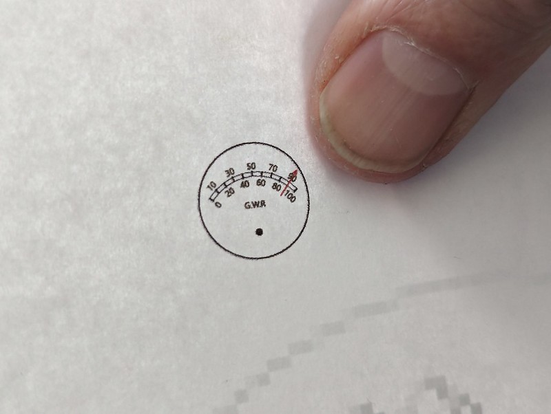 PXL_20240323_104846466 PXL_20240323_104846466 by Billy Roberts, on Flickr |
|