|
|
Post by Roger on Dec 26, 2023 23:14:43 GMT
So, here's the second attempt at the Pressure Gauge. The profile and step were machined with a 5.5mm Carbide 3-flute...  PXL_20231226_124544596 PXL_20231226_124544596 by Billy Roberts, on Flickr ... with the rest being roughed and finished with a 2mm cutter. The design was modified to make any internal radii 1mm or less so I could use that size of cutter. Anything smaller, and the flute length wouldn't have been long enough unless I bought a long series cutter. The M1 fixing holes were also added at this stage...  PXL_20231226_150621892 PXL_20231226_150621892 by Billy Roberts, on Flickr ... as were the 1mm pivot holes for the gears before turning the 4th Axis into the horizontal position. The centre finder was used on either side of the stock diameter which was set accurately to the centre of rotation of the chuck before I started. The centre line is Z0, even though that's not the centre of the part. When you're creating tool paths in the CAM software, you set the origin and orientation of the X/Y/Z axes wherever you like. For this operation, it's obviously different to how it was machined on the end. Here, the X-axis is through the centre line of the chuck, while the Y-axis is front to back and the Z-axis is up and down. The end of the part is X0 and the centre of the stock is Y0Z0 Once you've set up the triad in one orientation, Alibre CAM can be told to re-orientate the axes simply by asking it to rotate the triad around any of the axes by any amount. That just means turning it through 90 degrees in the Y-axis to tip it over, and then whatever angles you need in the X-axis to spin it round to bring the appropriate face to the top. The key point is this. Once you've set up the offsets to where the origin is, you can spin the axes around and the centre of the part remains in the same place. So for the situation below, I've just told the X-axis to turn through 22 degrees. I can see on the 3D model that the Z-axis is then pointing upwards when the slot shown is in the right orientation. I know this sounds complicated, but if I could show you the axes moving in a live demonstration, you'd see that it's pretty simple. Knowing that the origin of the triad stays where it is, regardless of how you turn the axes means it's dead easy to output tool paths for any face you want to present in the Z-axis direction. All of the NC programs come out in the wash, registered to each other.  PXL_20231226_195400783 PXL_20231226_195400783 by Billy Roberts, on Flickr Here's a wobbly video of the slots being added with a 0.8mm PCB Burr. I've defined the tool path as just a single line running down the side of the slot. The depth of cut is 20microns, or just under a thou in old money. The two cuts took an hour and a half to complete. It could probably be done much faster, but there's no point in risking breaking the cutter and having to start again.  PXL_20231226_195409537.TS PXL_20231226_195409537.TS by Billy Roberts, on Flickr Finally the 1.2mm hole for the register on the inlet fitting was added and checked to see that it breaks through into the slot.  PXL_20231226_222101737 PXL_20231226_222101737 by Billy Roberts, on Flickr Finally that was parted off and the back tidied up with a file and wet & dry on the surface table. 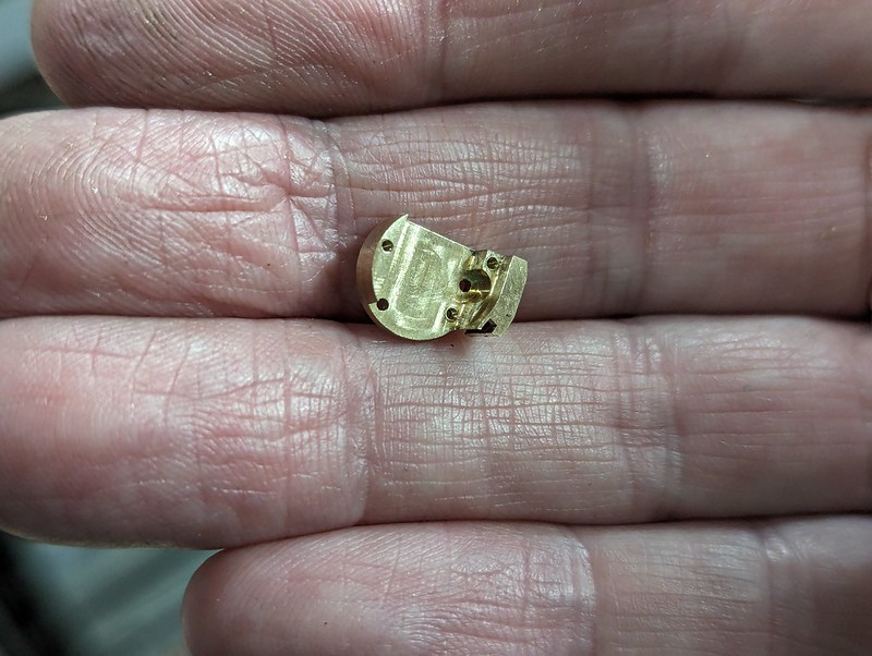 PXL_20231226_223647331 PXL_20231226_223647331 by Billy Roberts, on Flickr |
|
|
|
Post by Roger on Dec 28, 2023 23:02:52 GMT
This is the front bearing plate for the Pressure Gauge, with the relocated pivot hole to one side.  pxl_20231227_120523741 pxl_20231227_120523741 by Billy Roberts, on Flickr And this is going to be the 74 tooth quadrant. The blank was machined oversize and finished on the mill...  pxl_20231227_123204808 pxl_20231227_123204808 by Billy Roberts, on Flickr ... and the wire holes added as before. 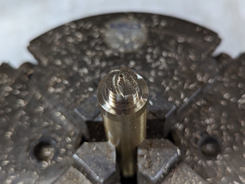 pxl_20231227_125145963 pxl_20231227_125145963 by Billy Roberts, on Flickr The setup is the same as before, using the 60 tooth gear cutter for the 74 tooth gear. Ideally I should have made a new cutter, but Module gear cutters usually are sold with a range of possible teeth since the profiles are very similar for similar numbers of teeth. We'll have to see how well these mesh. If it's not good enough, I'll make a new cutter.  pxl_20231227_132106174 pxl_20231227_132106174 by Billy Roberts, on Flickr 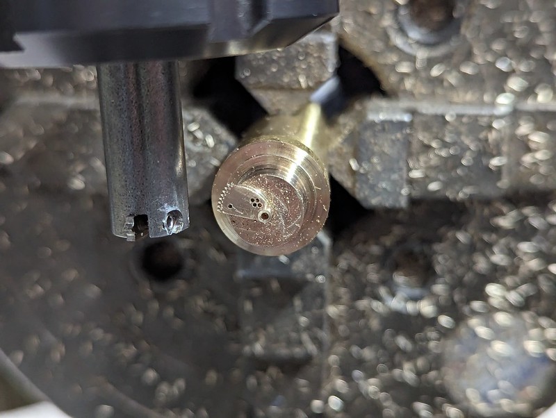 PXL_20231227_161031147 PXL_20231227_161031147 by Billy Roberts, on Flickr I thought I'd lost the 2.2mm diameter 12 tooth gear, but it turns out I'd just put it in the Ultrasonic Tank. Anyway, here's a spare one. 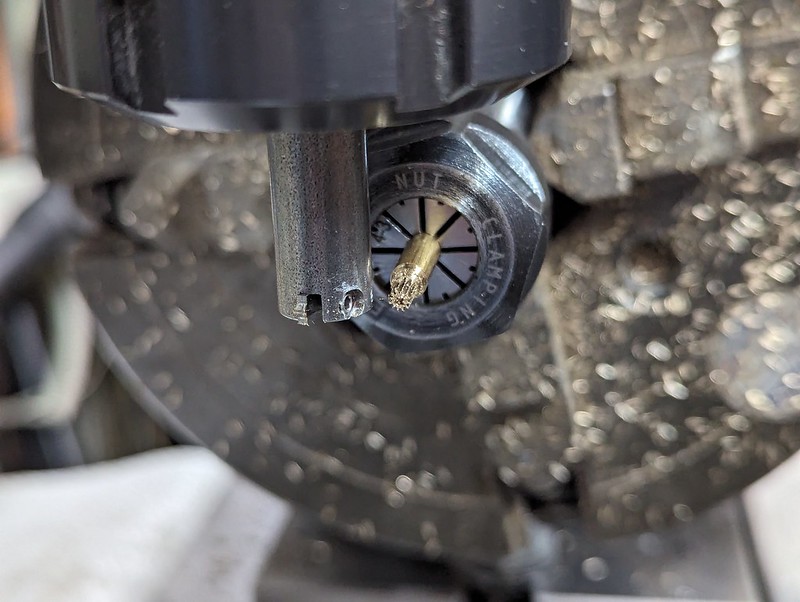 PXL_20231227_194203367 PXL_20231227_194203367 by Billy Roberts, on Flickr I could have desoldered the Union from the other Gauge body, but it's easy enough to just make a new one. The thread was screwed tightly into the Female M2.5 mandrel... 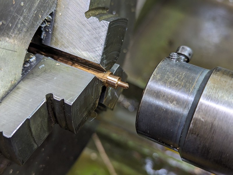 PXL_20231227_212246371 PXL_20231227_212246371 by Billy Roberts, on Flickr ... so the top details could be machined. 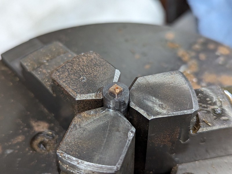 PXL_20231228_173346241 PXL_20231228_173346241 by Billy Roberts, on Flickr Being square, that was held in the Vise so that it could be unscrewed. It was then Silver Soldered onto the body using the same fixture as last time. I managed to use a smaller piece of Silver Solder wire this time, and the joint is much neater.  PXL_20231228_175748845 PXL_20231228_175748845 by Billy Roberts, on Flickr A quick sanity check to make sure there's a passageway between the input and the Bourdon Tube slot. 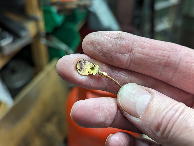 PXL_20231228_195433480 PXL_20231228_195433480 by Billy Roberts, on Flickr I've countersunk the bearing holes on the outside a little to give them a little more tolerance to misalignment when the cover bearing plate is fitted. The Phosphor Bronze 1mm pivot rod is being fitted with screw lock to the gear. I'll wipe off the excess when it's gone off. 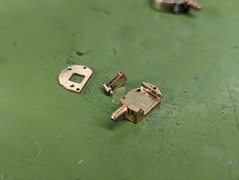 PXL_20231228_214516467 PXL_20231228_214516467 by Billy Roberts, on Flickr |
|
|
|
Post by Doug on Jan 15, 2024 11:39:56 GMT
Wow I keep chasing you down the miniaturised rabbit hole but you just keep going 😂 I definitely can not get this small. Amazing job though.
|
|
|
|
Post by Roger on Jan 15, 2024 16:40:13 GMT
Wow I keep chasing you down the miniaturised rabbit hole but you just keep going 😂 I definitely can not get this small. Amazing job though. Thanks Doug. I'm still trying to find the time this needs to get enough travel. Hopefully there will be an update soon. |
|
|
|
Post by Roger on Jan 23, 2024 12:13:11 GMT
I've been very short of time lately, so not much progress really on the Pressure Gauge. However, I did make a skinny 3.5mm wide tube which actually has a small split down the side, but went from this... 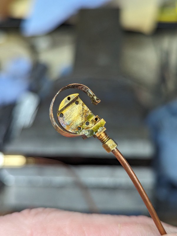 PXL_20240121_191714233 PXL_20240121_191714233 by Billy Roberts, on Flickr ... to this, which is a crazy amount of movement. That's enough to show me that this is going to work when I get the proportions right. 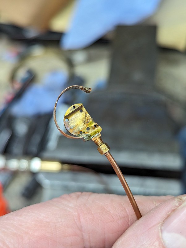 PXL_20240121_191725361 PXL_20240121_191725361 by Billy Roberts, on Flickr Silver Soldering the joint neatly without too much going everywhere is tricky. The two below were prepared in the same way, with Tippex and a tiny strip of masking tape to leave the joint exposed. However, there are clearly issues with this masking method. 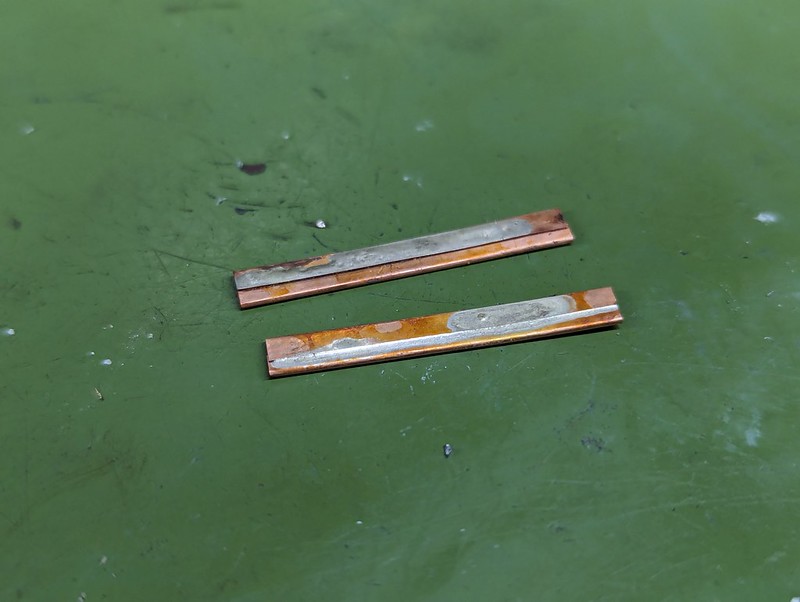 PXL_20240123_101133906 PXL_20240123_101133906 by Billy Roberts, on Flickr I thought it was about time I did a few experiments to see if there isn't something better for this job. Here are three possible candidates, with Silicone Gasket, Nail Varnish, and Etch Primer on the right. 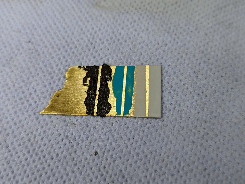 PXL_20240123_110754017 PXL_20240123_110754017 by Billy Roberts, on Flickr I just laid a length of 0.5mm Silver Solder wire on the exposed metal... 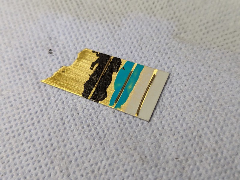 PXL_20240123_111500466 PXL_20240123_111500466 by Billy Roberts, on Flickr ... smothered them in flux...  PXL_20240123_111851102 PXL_20240123_111851102 by Billy Roberts, on Flickr ... and heated them. Clearly the Etch Primer is useless, acting more like a flux than anything. The Nail Varnish worked on the top part, but might have been spoiled by the Etch Primer at the bottom. The Silicone Sealant wasn't much good. 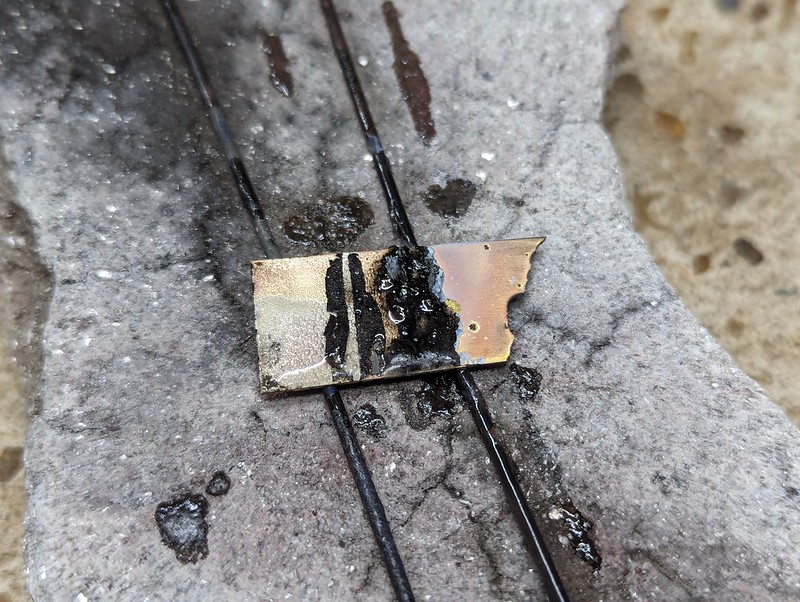 PXL_20240123_112218319 PXL_20240123_112218319 by Billy Roberts, on Flickr Here that is cleaned up, and the middle one looks the best by far. 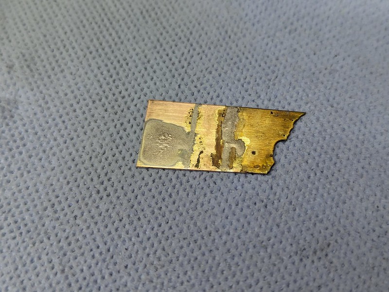 PXL_20240123_114814401 PXL_20240123_114814401 by Billy Roberts, on Flickr One concern I had was that the Nail Varnish would end up being difficult to remove, but it doesn't seem to bake on. I'll use that for the next experiments. |
|
|
|
Post by RGR 60130 on Jan 23, 2024 12:51:34 GMT
Another one to try is the black lead you use for cast iron fireplaces. In the war years when engine spares were in short supply my father would cast solid white metal bearings in situ using the black lead to stop the white metal sticking to the crank shaft. Might be worth a try if you have a tube on the ‘come in handy’ shelf.
Reg
|
|
|
|
Post by flyingfox on Jan 23, 2024 14:25:31 GMT
Greetings, I have always used typewriter correction fluid for this job, being clay based it washes of easily afterwards. Hard part is getting any.
regards
Brian B
|
|
|
|
Post by Roger on Jan 23, 2024 21:02:52 GMT
Another one to try is the black lead you use for cast iron fireplaces. In the war years when engine spares were in short supply my father would cast solid white metal bearings in situ using the black lead to stop the white metal sticking to the crank shaft. Might be worth a try if you have a tube on the ‘come in handy’ shelf. Reg Hi Reg, Is this the sort of thing you have in mind? It's a graphite based cream by the look of it. There are other similar ones that specifically say that they are not Graphite too. I wonder which one would be better? |
|
|
|
Post by Roger on Jan 23, 2024 21:05:24 GMT
Greetings, I have always used typewriter correction fluid for this job, being clay based it washes of easily afterwards. Hard part is getting any. regards Brian B Hi Brian, I've been using Tippex up to this point, is that what you use? It does seems to work fairly well, but it's fragile and isn't easy to apply neatly. It also has a tendency to wick into joints because it's very watery. |
|
JonL
Elder Statesman
   WWSME (Wiltshire)
Posts: 2,990
|
Post by JonL on Jan 23, 2024 21:14:02 GMT
Thats the problem I've had with modern tippex, it doesn't seem to mix well in the bottle. You just end up with watery mess which is hard to apply to the areas you want.
|
|
barlowworks
Statesman
  Now finished my other projects, Britannia here I come
Posts: 878 
|
Post by barlowworks on Jan 23, 2024 23:26:53 GMT
You can get Tippex in strip form with its own applicator, it’s on a roll and you just put it where you want it. Might be worth a try.
Mike
|
|
|
|
Post by flyingfox on Jan 24, 2024 8:07:40 GMT
Greetings, a long time ago, when I closed my office, I "bagged" the remaining stock of correction fluid, not Tippex, but a cheaper brand, and it is white. I have 2 bottles left, and mixed with a little water & alcohol keep fluid. I think graphite is a no no.
Never tried the strip.
What about marking blue/fluid, that might work, and should be removeable?
Regards
Brian B
|
|
|
|
Post by Roger on Jan 25, 2024 11:21:43 GMT
I think I'll give the Nail Varnish a go on the next Bourdon Tube. It's thick enough to be applied without it wicking everywhere, and it seems to repel the molten Silver Solder. I'll report how that goes.
|
|
|
|
Post by Roger on Jan 27, 2024 20:54:45 GMT
Here's another batch of Bourdon Tubes for the next set of experiments. At this stage they've been formed over the 'U' and triangular shaped formers and also over some Stainless Steel strips. However, you can see how much these have sprung back.  pxl_20240125_212240275 pxl_20240125_212240275 by Billy Roberts, on Flickr These were carefully annealed, only just getting them Red hot. They're very thin, so you have to be cautious or they will melt. 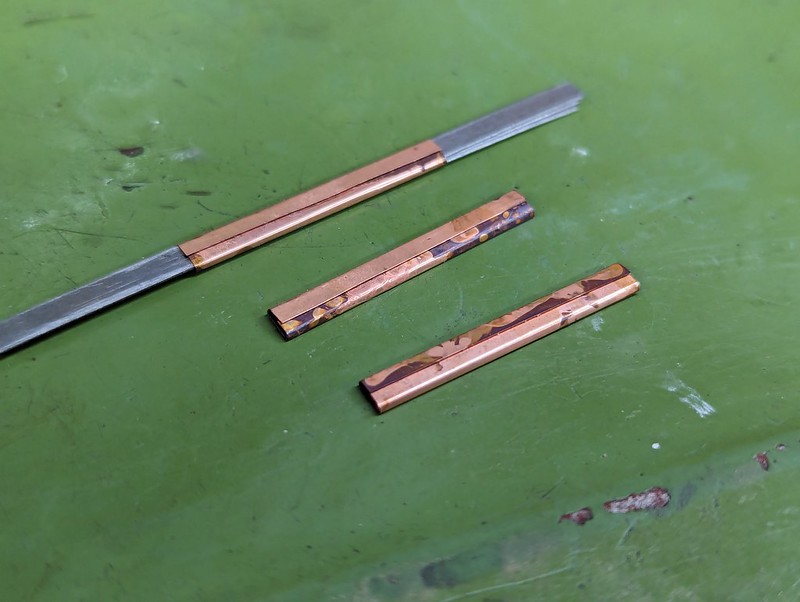 pxl_20240125_215816305 pxl_20240125_215816305 by Billy Roberts, on Flickr I applied a thin strip of masking tape where the Silver Solder is going to go... 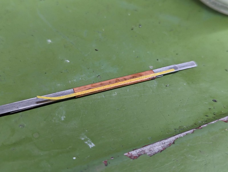 pxl_20240126_164001585 pxl_20240126_164001585 by Billy Roberts, on Flickr ... and then painted it all in Nail Varnish. 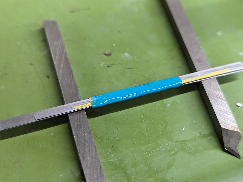 pxl_20240126_165051420 pxl_20240126_165051420 by Billy Roberts, on Flickr Applying it too thickly makes it stringy when pulling off the tape. 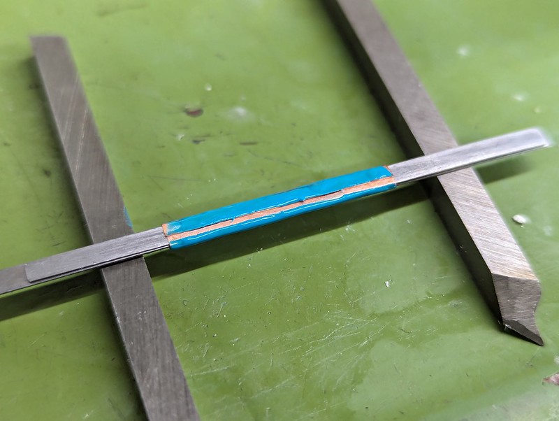 pxl_20240126_165147228 pxl_20240126_165147228 by Billy Roberts, on Flickr I left them for an hour to go off before tidying up with a scalpel. I think it would be better to add a second piece of masking tape to just cover the edge to keep that clean. If a little Silver Solder ends up on the top, it can be filed off easily enough. I ended up having to slide some thin Wet & Dry under the joint to get it all clear of the Nail Varnish. That probably ended up making a slight gap which isn't ideal. 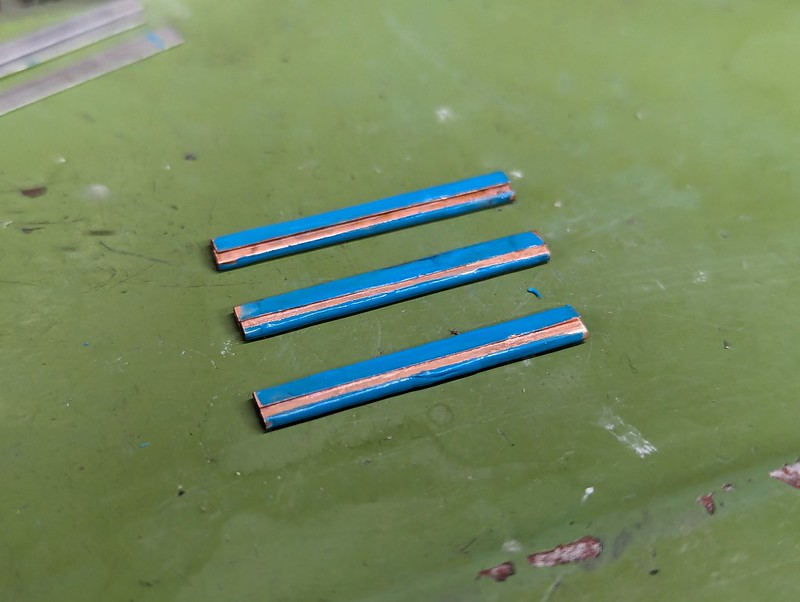 pxl_20240126_191738670 pxl_20240126_191738670 by Billy Roberts, on Flickr I kept them well apart so they could be heated separately. Each has three lengths of 0.5mm wire, covering about 2/3 of the overall length.  pxl_20240126_192814730 pxl_20240126_192814730 by Billy Roberts, on Flickr The Nail Varnish seems to work really well... 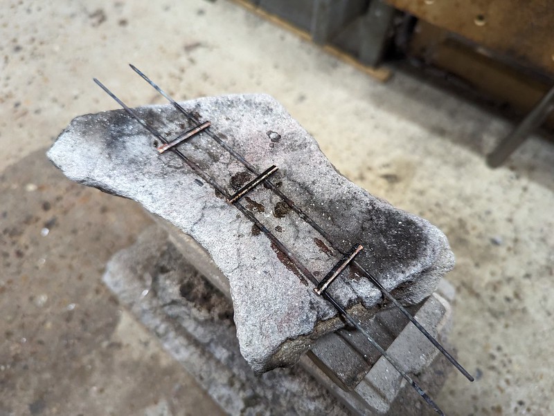 pxl_20240126_194330895 pxl_20240126_194330895 by Billy Roberts, on Flickr ... and this is how they came out of the Ultrasonic Tank. The back one didn't take all the way along, so I'll have to fix that. 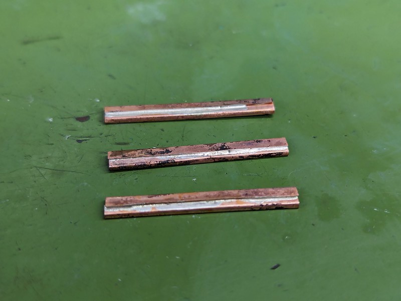 PXL_20240126_201702459 PXL_20240126_201702459 by Billy Roberts, on Flickr The first one I rolled was damaged while using the rollers. The problem is that the thickness isn't completely even all the way around because the joint isn't perfect. Here's the second attempt, partially formed and being annealed yet again. I've already done this twice to get to this point to make sure the sides don't split and the ripples on the inside are being rolled flat. I've found it best to leave the thin Stainless Steel strips inside for this process. It's hard to get them back in, and their bulk helps when you're trying to avoid overheating it. The joint is away from the blow torch so it's cooler than the bottom and sides. I heated it slowly until the colours flushed, and then you know it's almost Red hot. Just a little more heat and I could see it briefly turn Red. That's all it took, and the joint didn't melt.  PXL_20240127_195059293 PXL_20240127_195059293 by Billy Roberts, on Flickr I added some spring washers to the rolling jig so that I'm controlling the force between the rollers rather than the absolute distance. This works much better, it's not so brutal on the high spots. 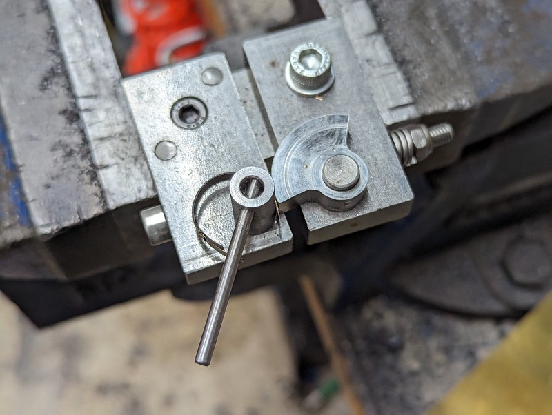 PXL_20240127_195337134 PXL_20240127_195337134 by Billy Roberts, on Flickr This is about finished...  PXL_20240127_200706645 PXL_20240127_200706645 by Billy Roberts, on Flickr ... you can see how many shims were inside. 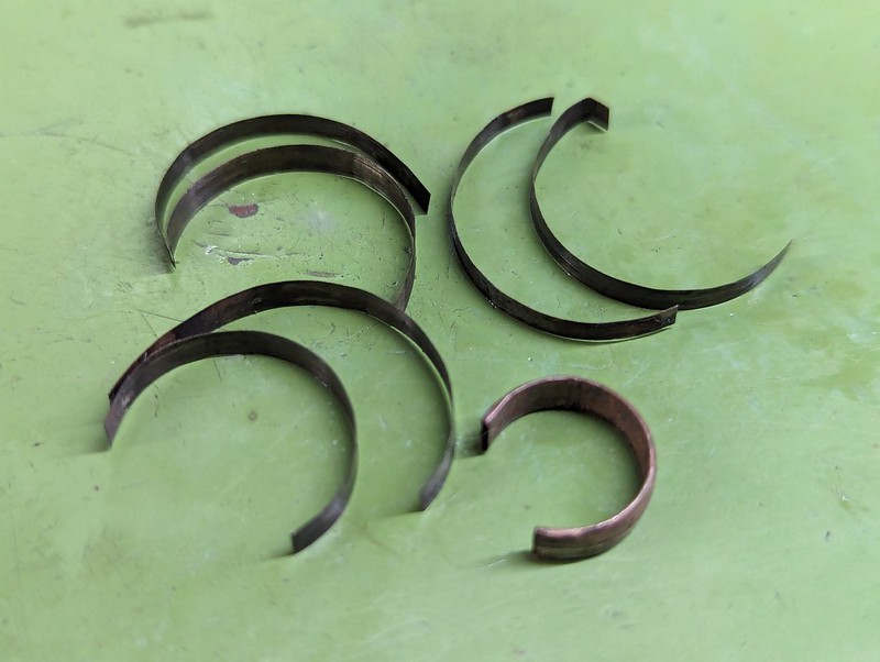 PXL_20240127_200856094 PXL_20240127_200856094 by Billy Roberts, on Flickr I'm not sure if this is the right thickness, it might need to be a flatter section. I'd still start out the same way, but remove a couple of shims. I've put it in Citric Acid overnight to clean it up so I can Soft Solder it into the Gauge Body and give it a try. I have a feeling that it's too rigid. Overall, this looks to be a repeatable process. It's just a matter of finding the right cross section to get the desired deflection. |
|
|
|
Post by Roger on Jan 29, 2024 12:05:35 GMT
I tried the new Bourdon Tube, but had the same issue are before with the direction of movement of the free end being upwards rather than out sideways. I think the issue is that the attachment point for the tube is too far down, it needs to be further round the diameter. That's a problem though, because there's no easy way to create the curved channel. However, I probably don't need to do that anyway. Below is a possible solution which uses part of the base (Purple) to support the tube and prevent it from bending by Soft Soldering it on the inside. I can Soft Solder a piece of shim on the outside if it still manages to bend there. I think I can get enough travel on the Bourdon Tube as long as it moves in the right direction.  Supported Bourdon Tube arrangement Supported Bourdon Tube arrangement by Billy Roberts, on Flickr Anyway, it's a simple solution which is worth a try. One thing I noticed with the Bourdon Tube I just made is that it's easy to end up with one section where it gets flattened more than another. That tends to act as a hinge point. I'll have to watch out for that on the next one. |
|
|
|
Post by chris vine on Jan 29, 2024 22:36:50 GMT
Hi Roger, could you avoid all the trouble of soldering by starting with a small copper tube with something down the middle while you roll it flat and thin?
Then dissolve iron wire with alum or melt solder out….
Like you, I like to look for different solutions!
Chris
|
|
jma1009
Elder Statesman
  
Posts: 5,919
|
Post by jma1009 on Jan 30, 2024 19:25:49 GMT
Hi Roger,
I would be most interested in you trying the ‘FSD’ drawn phos bronze tube as an experiment.
Cheers,
Julian
|
|
|
|
Post by brucevoelkerding on Jan 30, 2024 19:53:08 GMT
didn't Roy Amsbury or perhaps Bill Carter describe making a Pressure Gauge using a Tube supported with an internal "Mandrel" and turned on the Lathe ? I am sure I read that in Model Engineer.
|
|
|
|
Post by simplyloco on Jan 30, 2024 20:37:18 GMT
didn't Roy Amsbury or perhaps Bill Carter describe making a Pressure Gauge using a Tube supported with an internal "Mandrel" and turned on the Lathe ? I am sure I read that in Model Engineer. it was Roy Amsbury. Search 'Small Boiler Fittings'. |
|
|
|
Post by Roger on Jan 30, 2024 20:58:26 GMT
Hi Roger, could you avoid all the trouble of soldering by starting with a small copper tube with something down the middle while you roll it flat and thin? Then dissolve iron wire with alum or melt solder out…. Like you, I like to look for different solutions! Chris Hi Chris, Way back at the start, a couple of years ago, I turned some Phosphor Bronze ones on a mandrel that they were Soft Soldered to. That's certainly possible, but I found the Phosphor Bronze cracked when forming it. However, I think I might have succeded if I had annealed it multiple times. I don't think Copper is suitable for that process, it's horrible to machine and I don't think it's springy enough. I might return to that method at some point. although getting an even and really thin wall is challenging. Putting Solder down the middle could work though. |
|
 PXL_20231226_124544596 by Billy Roberts, on Flickr
 PXL_20231226_150621892 by Billy Roberts, on Flickr
 PXL_20231226_195400783 by Billy Roberts, on Flickr
 PXL_20231226_195409537.TS by Billy Roberts, on Flickr
 PXL_20231226_222101737 by Billy Roberts, on Flickr
 PXL_20231226_223647331 by Billy Roberts, on Flickr
 PXL_20231226_124544596 by Billy Roberts, on Flickr
 PXL_20231226_150621892 by Billy Roberts, on Flickr
 PXL_20231226_195400783 by Billy Roberts, on Flickr
 PXL_20231226_195409537.TS by Billy Roberts, on Flickr
 PXL_20231226_222101737 by Billy Roberts, on Flickr
 PXL_20231226_223647331 by Billy Roberts, on Flickr


