|
|
Post by ejparrott on Nov 10, 2013 12:29:29 GMT
It really is time I started a build thread for my engine, especially with progress starting to be made. I'm copying this over from another forum, so if it feels like it doesn't quite flow that's why! This is the prototype in the Narrow Gauge Railway Museum, on the Talyllyn Railway, Tywyn. 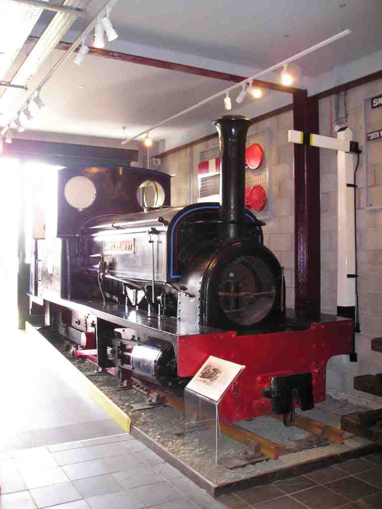 She was built in 1897 by the Leeds manufacturer Manning Wardle and Co., for the Cilgwyn Slate Quarry in North Wales, as a 'Mainline' locomotive. Dispatched on July 16th 1897, she carried the builders number 1382, but carried no fleet number. She remained working at Cilgwyn until May 12th 1928 when she was sold, for £150, to the Penrhyn Quarry, along with a Hunslet engine - builders number 554 of 1897, otherwise known as 'Lilla', of which I have a 3½" gauge model. Both engines were towed along the Welsh Highland Railway (now reopened) to Dinas Junction, where they were transfered to the standard gauge wagons of the Great Western Railway, and transported to Port Penrhyn, where they arrived on May 28th. After delivery, 'Jubilee 1897' was put to work on the 'Red Lion' level of the Penrhyn Quarry, assembling trains in readiness for the journey the Port Penrhyn, on the 'Main-line', which was the job she was actually bought for. By the begining of 1929 she had moved down to the Port, but was returned to the Quarry in July 1930, reportedly with a 'weak' firebox. In January of 1937, she was finally taken into the company workshops, and re-gauged from the 1'10¾" of the Cilgwyn Quarry, to the 1'11 5/ 8" of the Penrhyn system...the fact that it took nearly ten years for this to happen doesnt say much about the standard of Penrhyn track... It is known that she was then laid up at the Coed-y-Parc locomotive facility from October 1940 until June '43, presuambly as a result of the weak firebox, but appears to have been put to work again until more time in storage in '45. She acctually recieved a new coat of Penrhyn black livery, albeit without the red and blue lining, in December 1946, but was then reported as laid up at Coed-y-Parc again until November 1950. In 1951 she returned to work at Red Lion level, and a shed list of May 1951 from Red Lion level lists her as being in service. It was all to end though on January 1st 1955, when the owners of Penrhyn Quarry decided she was past her best, and she was withdrawn from service, and consigned to the scrap line at Coed-y-Parc, where she had already spent many years. On the same line at the same time was 'Lilla', fitting that they should be together at the begining and at the end. They remained there, sheeted against the weather, with several other well known engines, until one cold day in December 1963. 'Lilla' was sold on and had a rebuild, begining a long road to her current status as an Historic engine on the Ffestiniog Railway, recently having recieved a new boiler. For 'Jubilee', preservation was also at hand for her, although far less taxing. She was transported to the Tywyn Wharf station of the Talyllyn Railway (Preservation Society), a railway which had begun 33 years before she was born and had been operated by the volunteers of the worlds first railway preservation society for 12 years. There she recieved a new coat of Penrhyn black livery, but with the red and blue lining this time, and she remained in dry storage as an exhibit on which the children could climb and pretend to drive. It was here, some time around 1990, that a certain small boy began to appreciate her for what she really was, and soon after began spending spare time on holidays to Tywyn, measuring and recording all her details, in readiness for the day when access to a workshop meant construction of a model could begin. That same small boy sits typing here now..... I started the project in earnest back in 2000, and I've been steadily drafting all the drawings since then. There's no drawings avaliable for a miniature, no-ones ever modelled it in large scale before, so I've had to do it all the hard way. I did manage to obtain a copy of the one remaining original works drawing from 1897 which still remains, its a general arrangement drawing so luckily covers almost every part in some detail or other. There's also no avaliable castings for this model, so I've had to turn to my skills as a pattern maker on a number of occasions already, with still many more to do. As my workshop is now coming together, work has started to pick up a bit. I've had the frame plates laser cut for a couple of years now, and the buffer beams a year ago. The wheel castings were made some 5 years ago, but they are now rough turned, I've been broaching keyways ready to fit them to the axles, and it won't be long before they're pressed on, and then I'll finish turn them and fit the tyres. This was the pattern for the wheels being turned on the big lathe at the club... 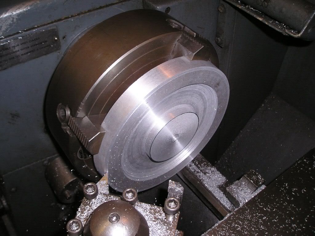 ...I actually made a wooden pattern to cast some aluminium blanks at Uni, which I've then turned into patterns themselves. The spoke profiles were then milled in on a vertical mill, by hand... 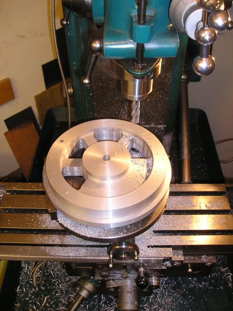 ...If I was starting this again, I wouldnt have bothered...now that I've got access to the wonders of CNC, I'd have machined the wheels straight from steel billets. While at Uni, I also turned both axles... 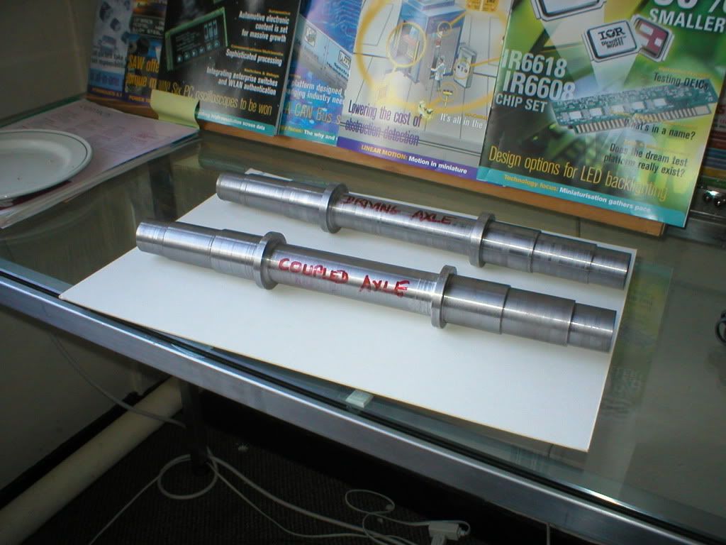 When I've finished broaching the keyways in the wheels, I'll be cutting the keyways in the axles, then it'll be pressing the wheels on. 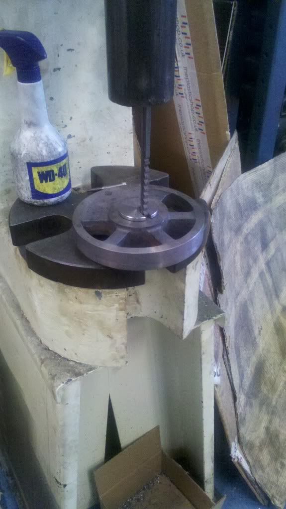 |
|
|
|
Post by ejparrott on Nov 10, 2013 12:31:16 GMT
Went to work early this morning to do some turning...I'm working on the cranks at the moment, I need to get them ready for fitting to the axles the same time as the wheels. These are the full size ones....  ...and these are the minaitures... 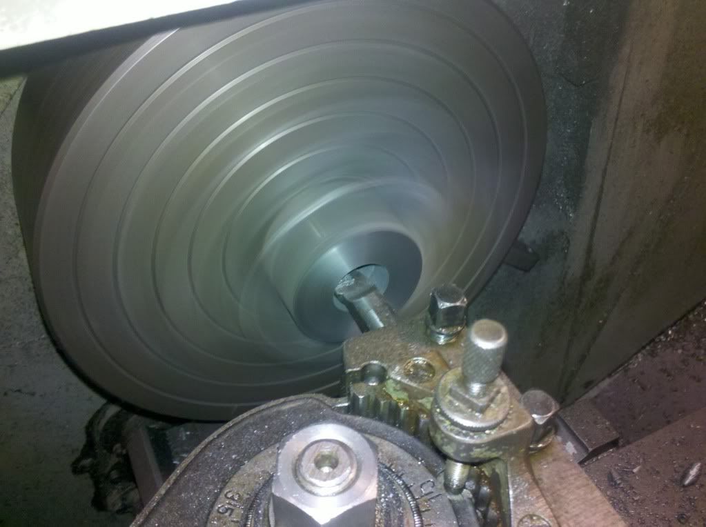 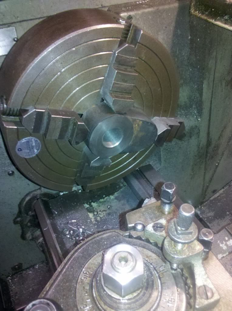 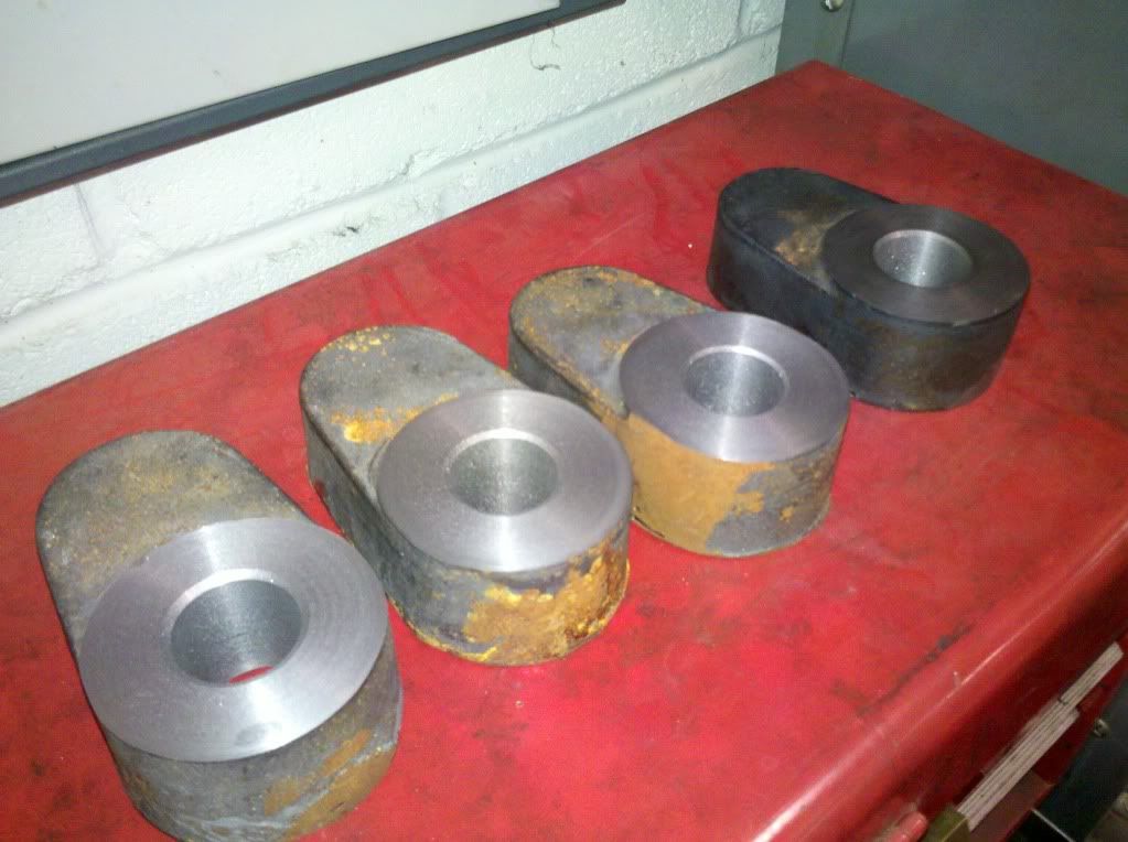 All four are bored to size -1/8" for the axle. Next step is to make a fixture plate for the lathe that will locate on the bore, and then hold the cranks at exactly 2" offset, and then I'll bore the holes for the crank pins. After a thorough inspection, I'll then finish bore the holes for the axles, leaving a press or shrink allowance. It might seem like an extra operation, but if I leave metal in the axle holes now, should I get one go stray when boring the crankpin holes I can correct it when I finish the main bores, which are less likely to wander as I can get a much bigger, sturdier boring bar in. It might be a little while before it gets made..... Now that the axle holes are bored, I can use them to locate off to put in the holes for the crank pins. I've made a fixture to hold them in the Colchester... 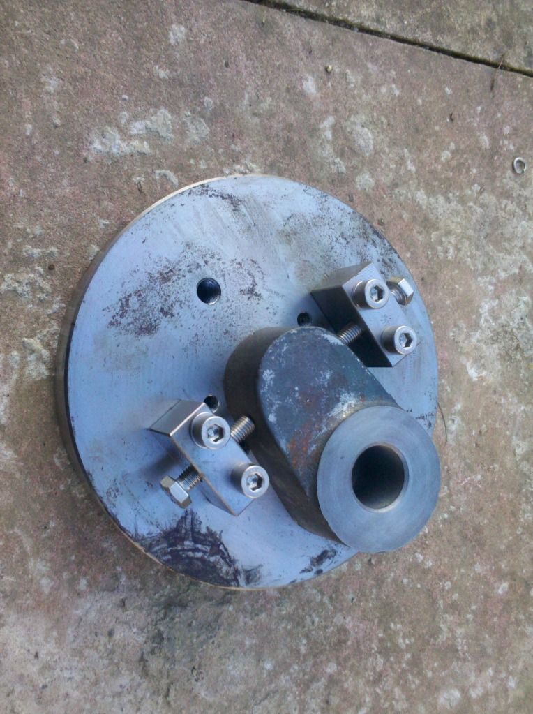 I'll drill and bore them out to size for the pins. I made the pins some time ago, which was the wrong thing to do really, I should have bore the crank webs and then made the pins to suit. Its easier to make a shaft fit a hole than a hole fit a shaft. Well, got some more done this week, I've cut the keyways in the leading axle for the wheels and cranks. Nice and easy, just 2 at each end, 90 degrees apart near enough, as long as the driving axle is identical. Two steel blocks bored for a close fit on the axle, with two sides machined accuratly at 90, then split and tapped for a clamp bolt and away we go... 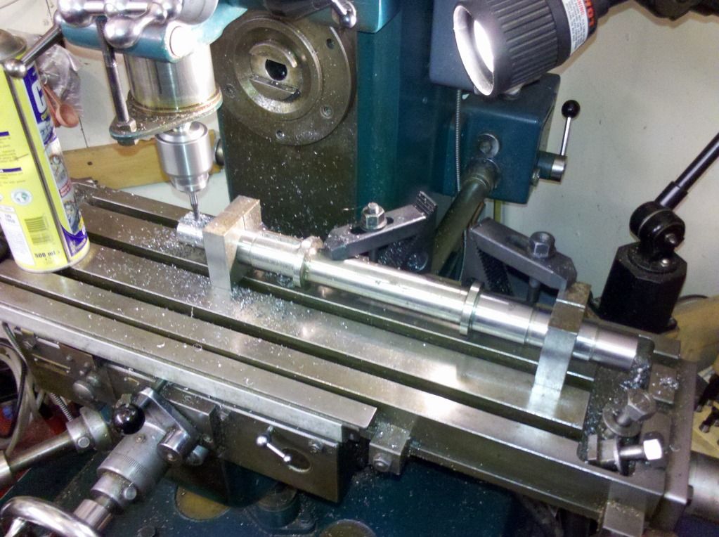 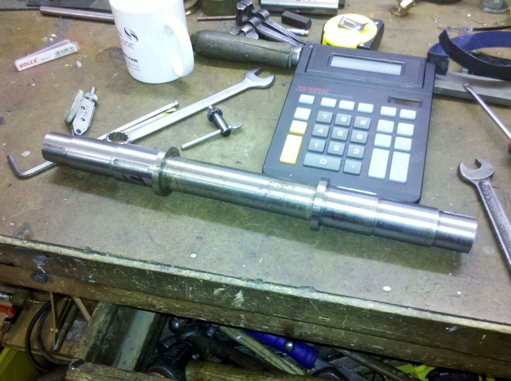 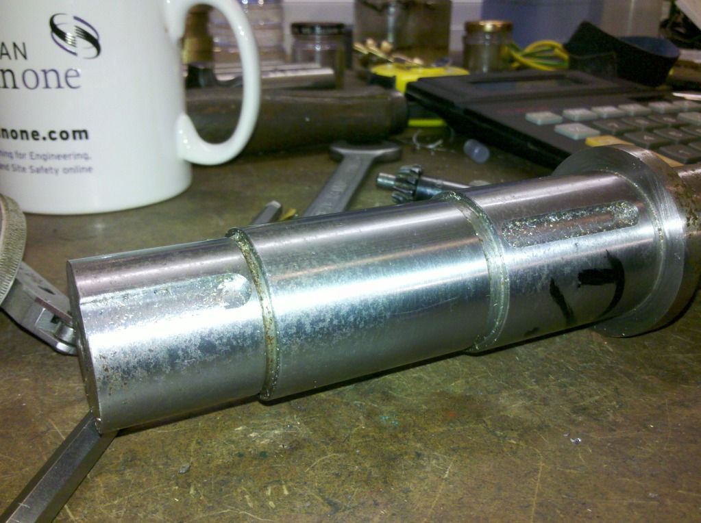 The driving axle is more complicated, as not only is there the 4 keyways for the wheels and cranks, but there's also 1 for the water pump which needs to be about 45 degrees to the cranks, to utilise the most powerful part of the stroke, but there's also the 4 keyways for the valve eccentrics which control the valve movements, they need to be very accuratly positioned to each other and to the cranks. If I'd worked at PT when I turned the axles I would have turned and milled them complete on one machine....If I could get on that machine now I'd say hang the cost and make new, but I can't. As it is I think I'll cut the wheel and crank keys the same way, then leave the clamps on and transfer to a rotary table and clock off the clamps to get it true....trouble is I need quite a long table mill to get the axles and the dividing head on...guess I'd better get mine up and running! |
|
|
|
Post by ejparrott on Nov 10, 2013 12:33:02 GMT
Good progress yesterday...very happy chappy........ 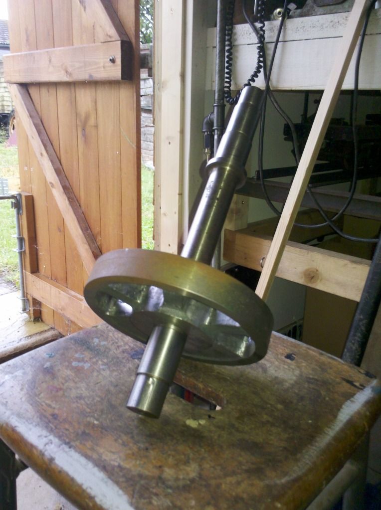 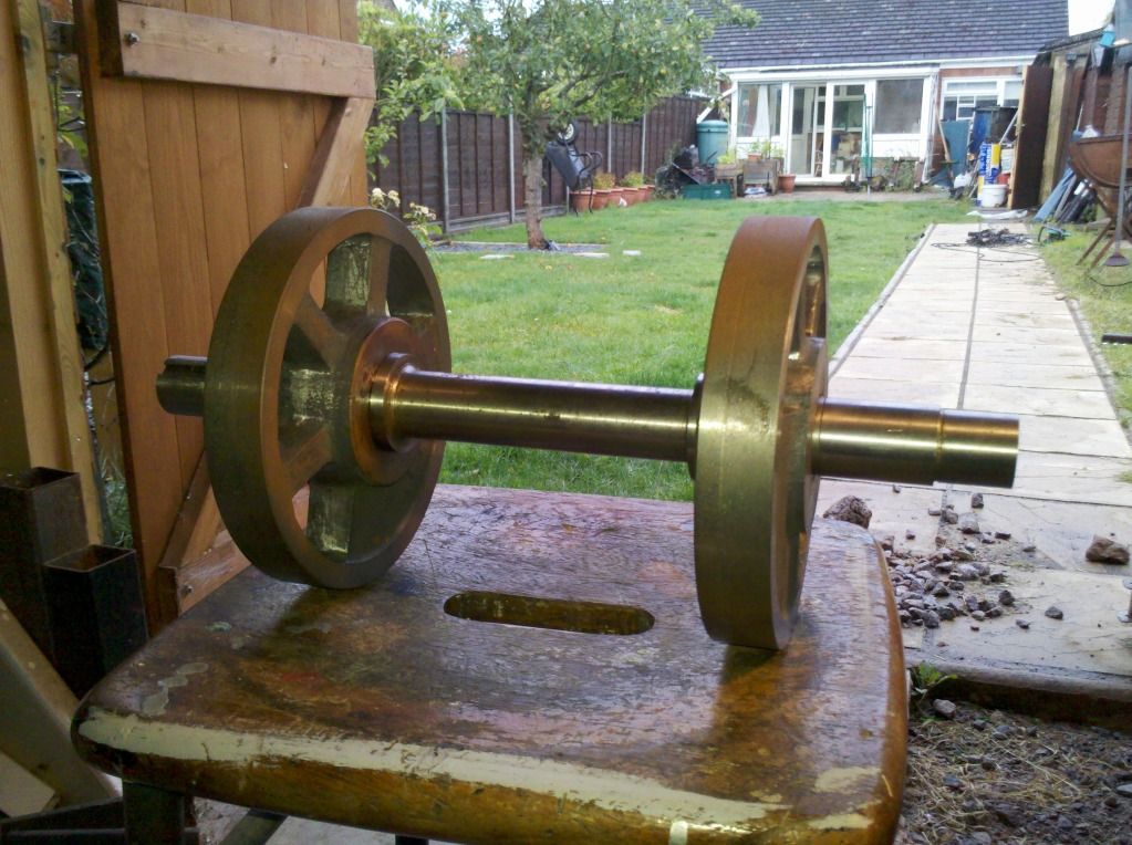 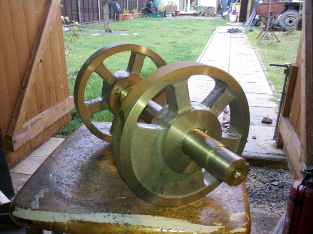 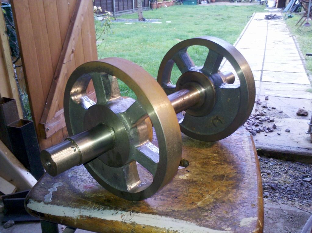 Thats the leading axle, now with both its wheels keyed, pressed and loctited into position. It'll probably get shotblast and painted next, to keep the oil out of the porous iron castings, before I finish turn the tyre diameters between centres. Tonight I'm going to cut the keyways for the wheels and flycranks using the same clamps, and then I need to figure out how to cut the other keyways in relative. Cut the 4 main keyways in the driving axles last night... 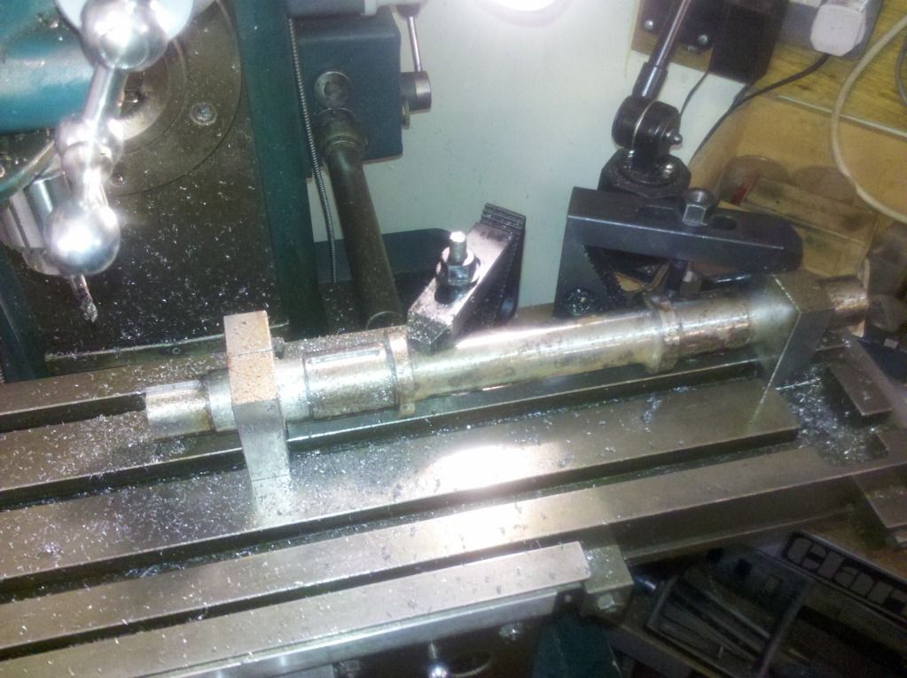 Just need now to confirm the angles of the keyways for the valve eccentrics and get them and the pump keyways cut before I can fit these wheels too. Got the locating peg made for the crank, and fitted the balance weight to the jig. I'm hoping on Wednesday to drill and ream the holes for the crank pins after work. Then I'll check and double check the centres, before finishing off the main bores to individual fits to each axle. The throw of the cranks is more important on a steam engine like this like than an IC engine in a LandRover. If the throw is different, it'll be impossible for the wheels to rotate without built in wear, as the coupling rods won't allow for it. 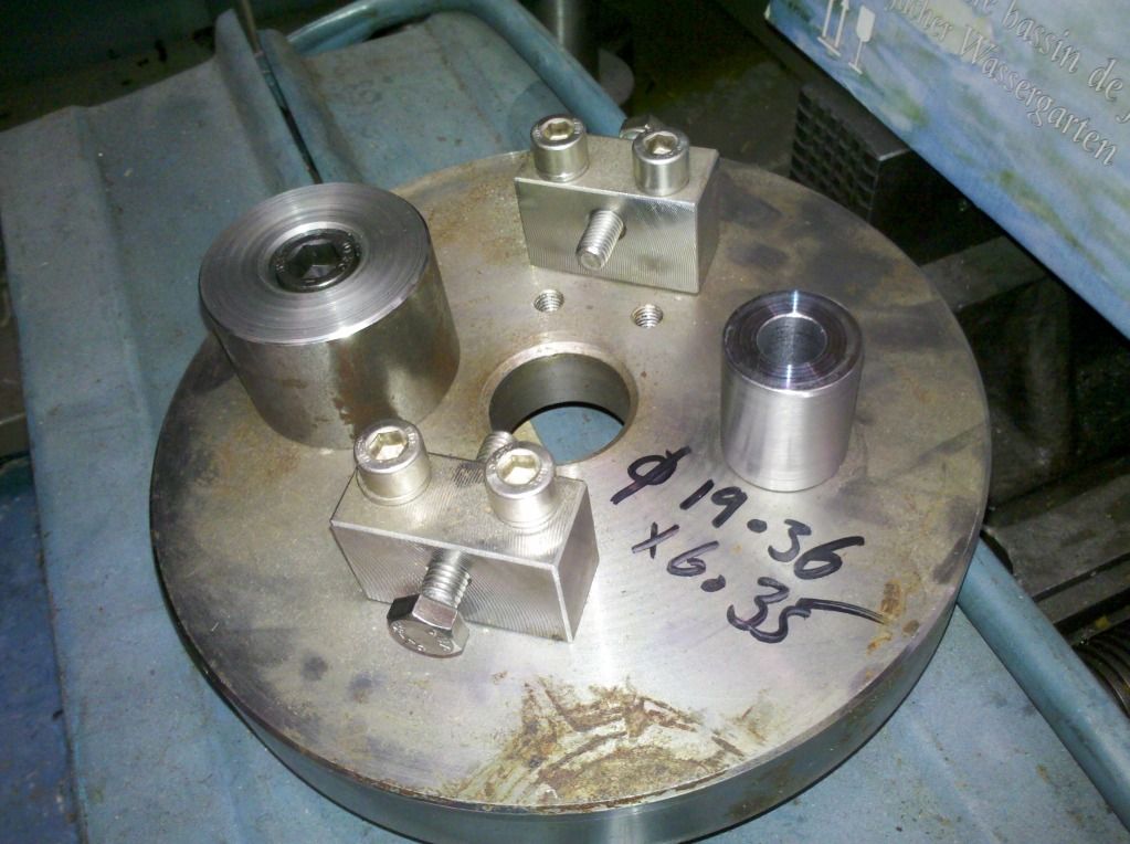 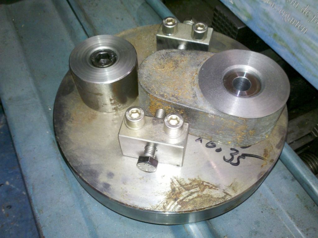 |
|
|
|
Post by ejparrott on Nov 10, 2013 12:35:45 GMT
Today I've skimmed the top of the chimney tube ready for fitting the cap, and started roughing out the cap itself....need to find an NC machine free to form the curve on really! First stage turning done on the chimney cap last night.... 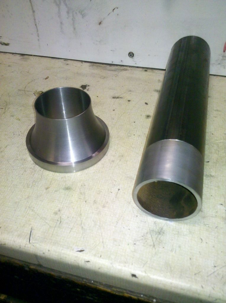 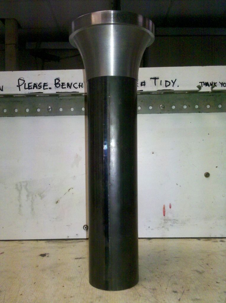 Find five minutes and I'll weld the cap to the tube over the weekend. Then I need to put it up, bore out the top of the tube to a size for the steam-raising blower, and turn the top detail on...need an NC machine for that again though. I've been to work this morning and done a bit more.... 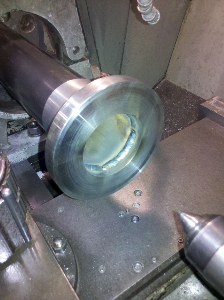 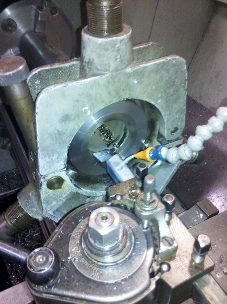 I've bored out the weld and took the top out to size and then set it up in the shaft lathe to turn the top rads by CNC on monday morning hopefully...programs all in the machine, chimneys clocked true, machines left on to warm up....now I just need to get up early on monday morning! 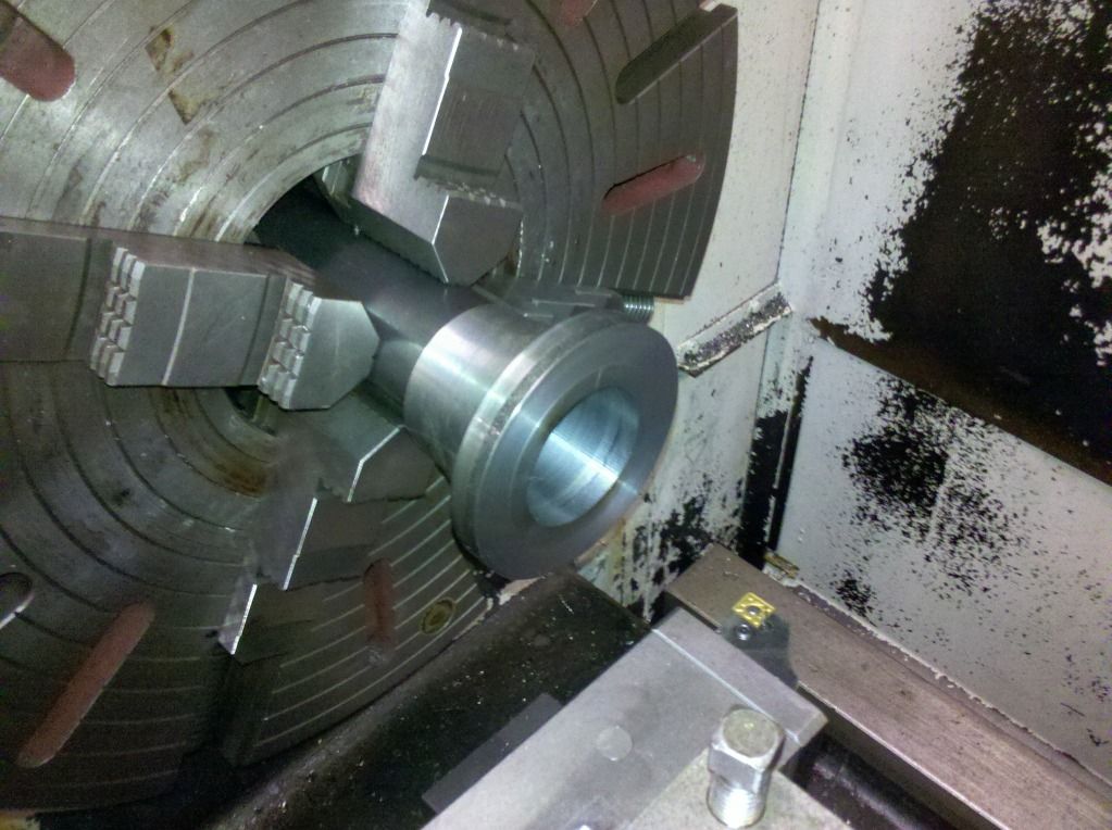 Cap finished!! 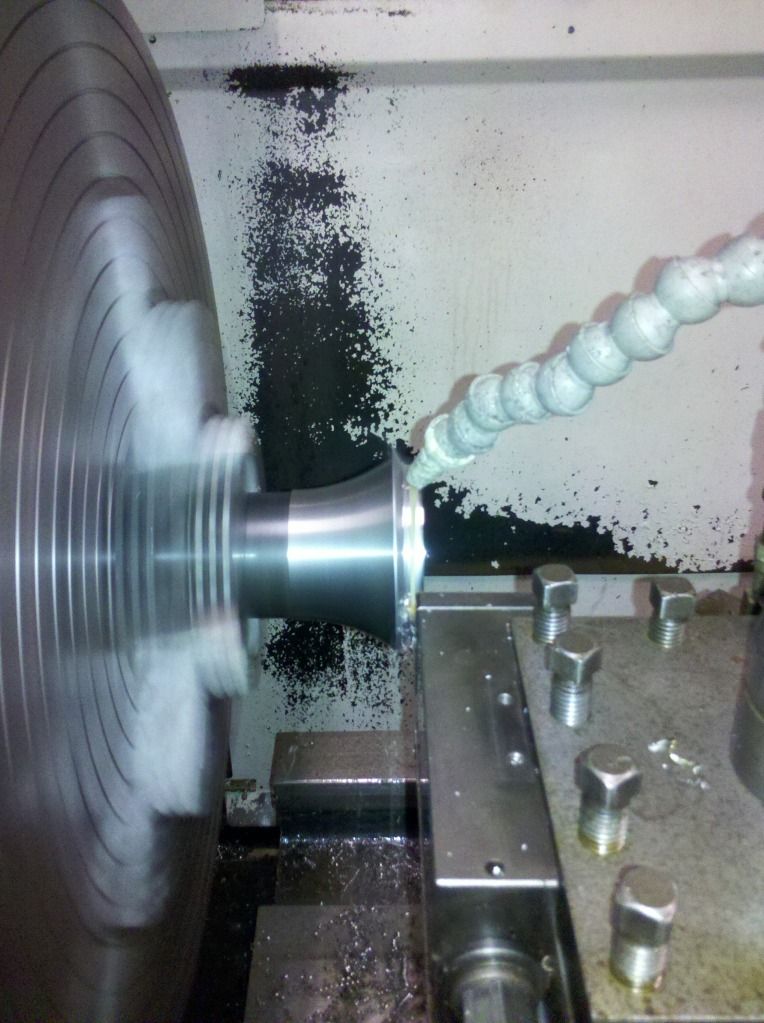 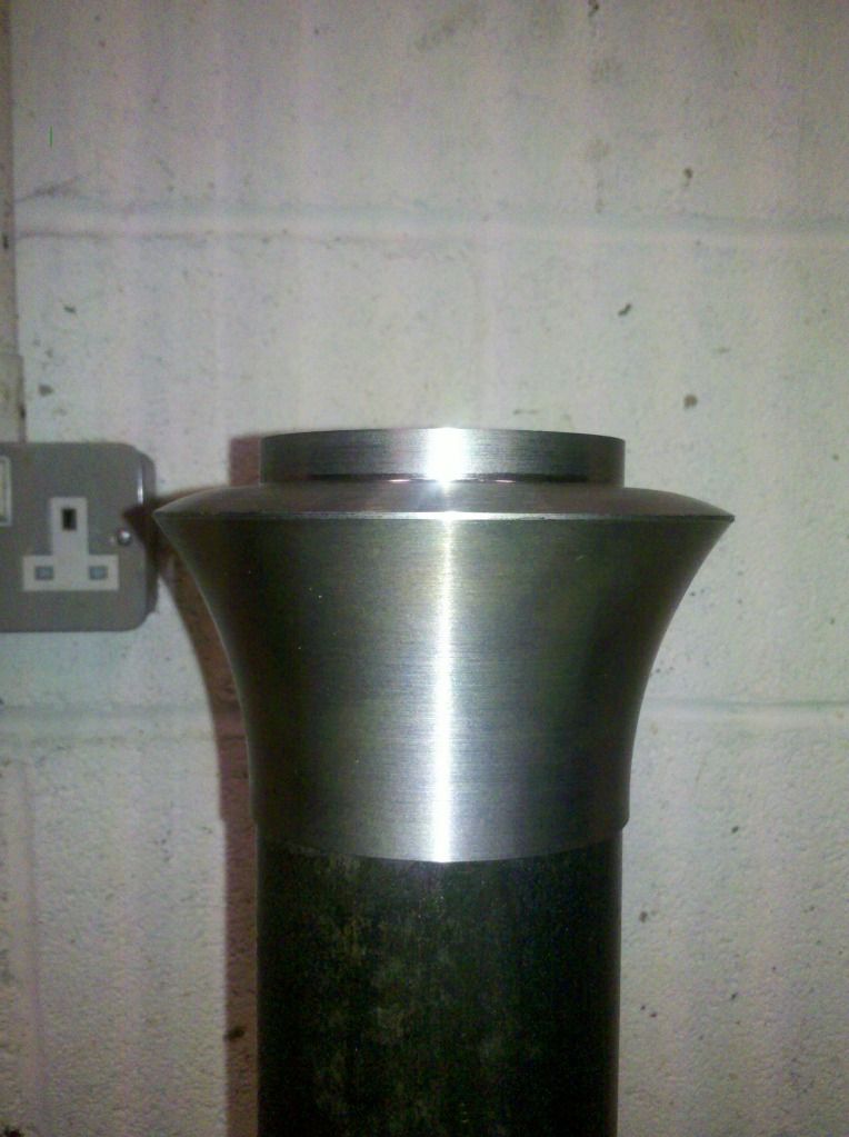 The beginings of the base, it's going to be 3-axis milled out of this part machined billet... 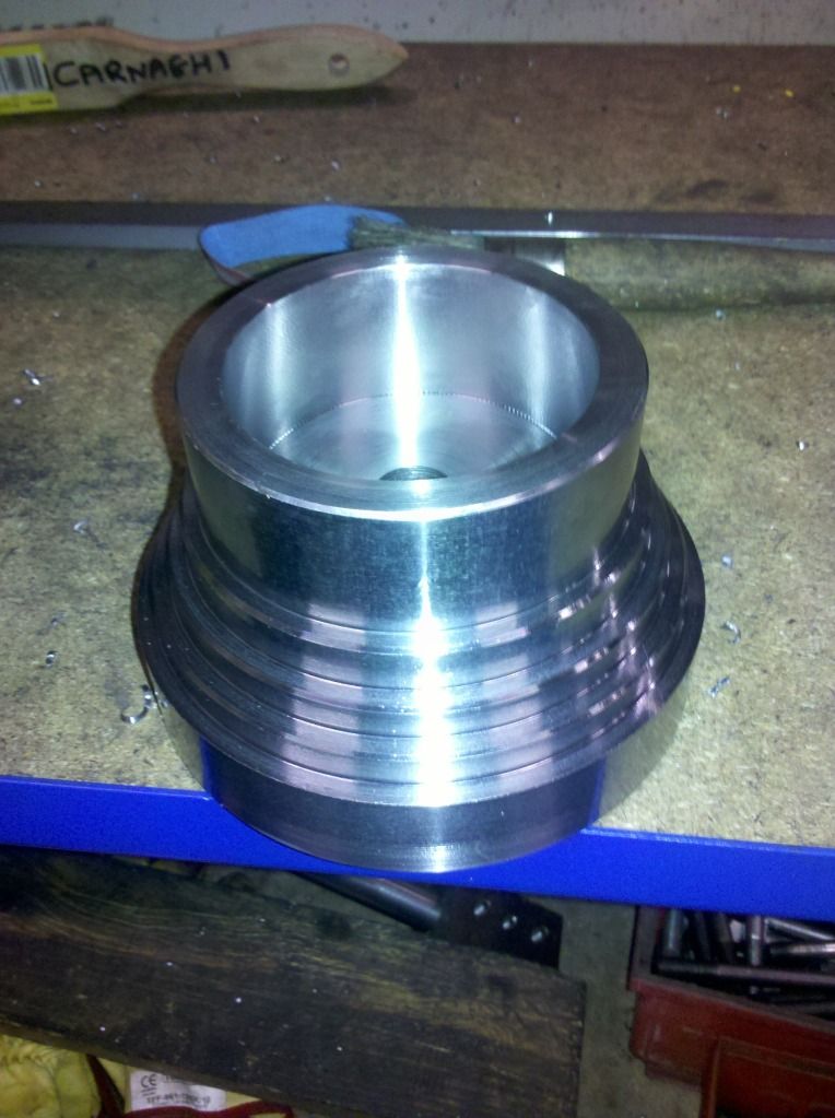 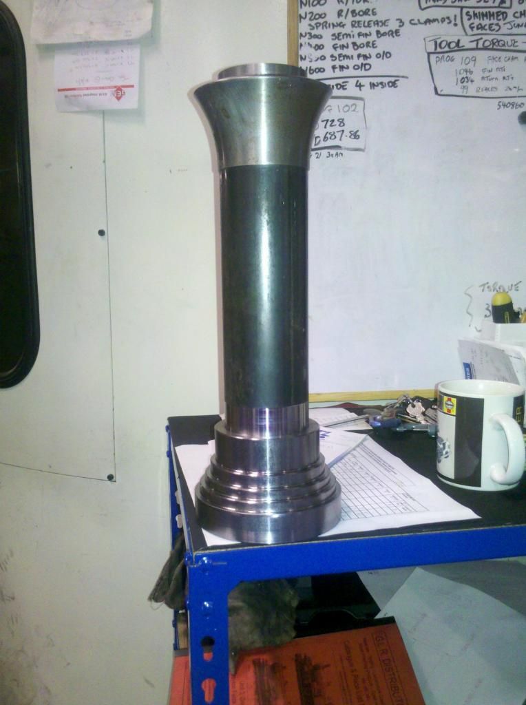 It should end up looking like this.... 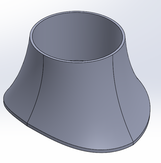 |
|
|
|
Post by ejparrott on Nov 10, 2013 12:38:30 GMT
Thinning the cranks down ready for grinding to thickness, and then finish boring for the axle ends.... 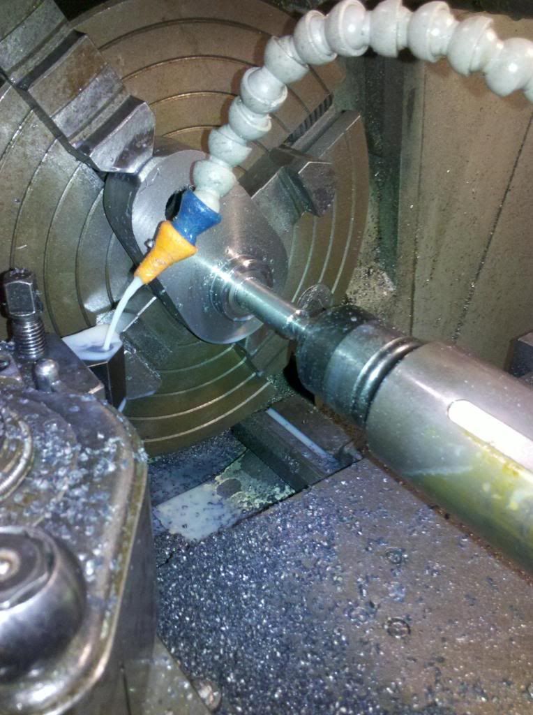 Keyways cut 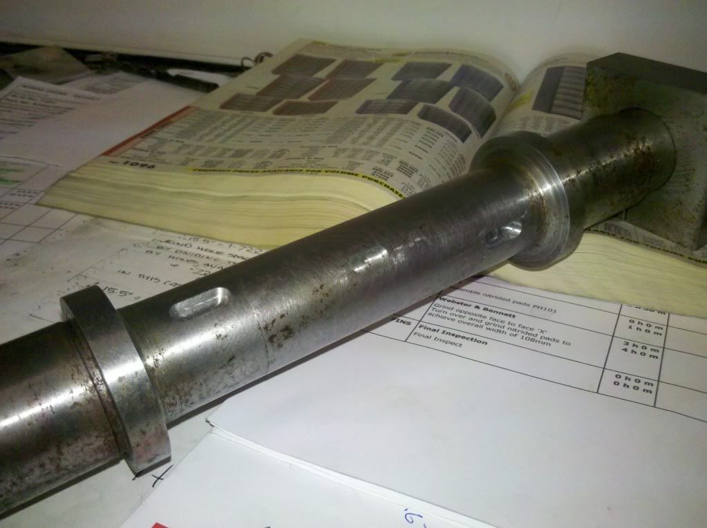 This shows the central keyway for the water pump eccentric, and two of the valve eccentric keyways, the other two being round the other side. I need to give it a quick clean up and then I can see about fitting these wheels too....if memory serves me right I still need to file the flashing off the wheel castings so it's going to be a few days. Then after that I need to finish taking the flycranks to thickness, fit the crank pins and fit the flycranks to the axles. That will then be up to the stage of making sure the tyre seats are true and taking them to size, and then we can see about making the tyres. This morning I did the first stage turning on the valve forks and spindles. These receive the motion from the eccentrics an expansion links and transfer the resultant movement to the valves. The large end will be machined into a square fork with a cross pin, the middle diameter is oversize and will be turned (or maybe ground) to suit the guides when they have been made (its easier to make a shaft fit a hole than a hole to fit a shaft). The little end then will be machined to fit another fork. 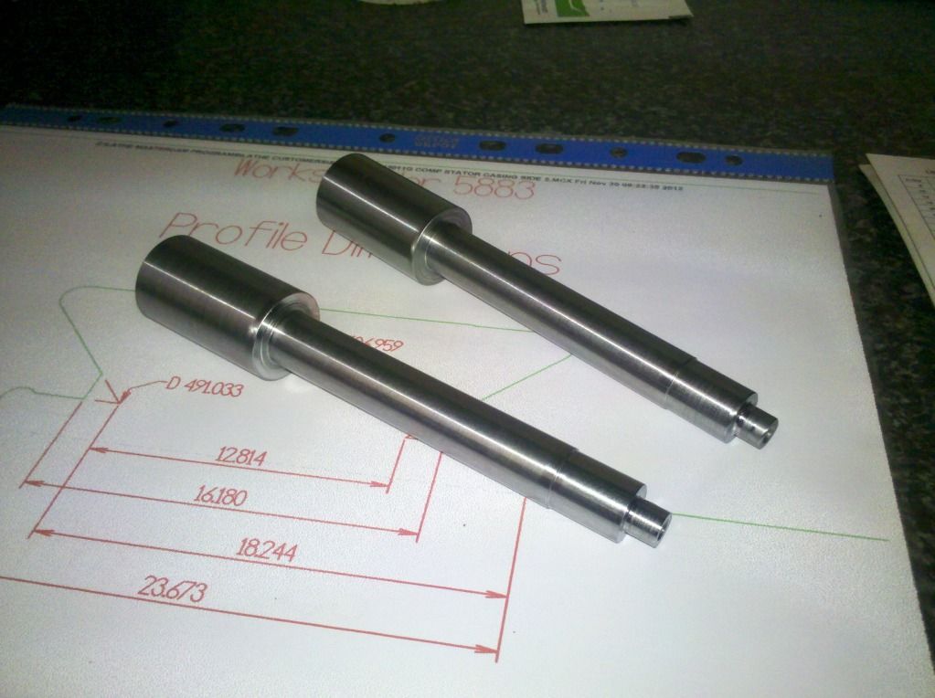 Robin and Dave will know what its all about.....it'll become more obvious when the rest of the valve gear starts going together! You're right Dave. We're taking a slight deviation from prototype with the design of the valve gear. Instead of driving direct in to the steam chest, the motion is being carried right up to the front to a cross shaft, and then back into the front of the steam chest. By doing this, we vastly reduce the length of the steam passages, and the mass of iron in the castings. We can also fit odd length cranks to the cross shaft and we're increasing the valve travel too. I'll be putting a turnbuckle in the shaft between these valve guides and the cross shaft. Still got to do the design of the guides, they're a split housing and a bloody complicated casting - they're most likely end up a fabrication with an iron bush lining them - it would be quite simple to replace with the new design of valve gear too. This is what the valve eccentrics look like....  There's 4 to made, 2 forward 2 reverse, split because the axle is reduced between the wheels, keyed so that they can't move on the axle, pinned together in pairs, and 82mm in diameter. Trying to find an in-expensive source of cast iron bar at the moment, its the delivery charges that kill it! The pair of eccentrics, one forward one reverse, on each side of the axle will look like this...  I'm a busy bee today..... Done the drawing for the eccentric rods now. These take the motion of the eccentrics on the axle, and use it to drive the expansion link. The expansion link creates a motion which is a development of the two eccentrics of the pair, and uses this to move the valve admitting steam to the cylinder ends.  This is how it fits... 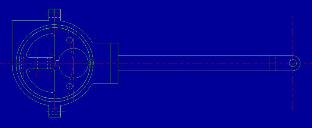 |
|
|
|
Post by ejparrott on Nov 10, 2013 12:53:17 GMT
Done a bit more this week. These are the motion brackets, laser cut, I've drilled all the fixing holes, and also started on the angles that will fix them to the frames... 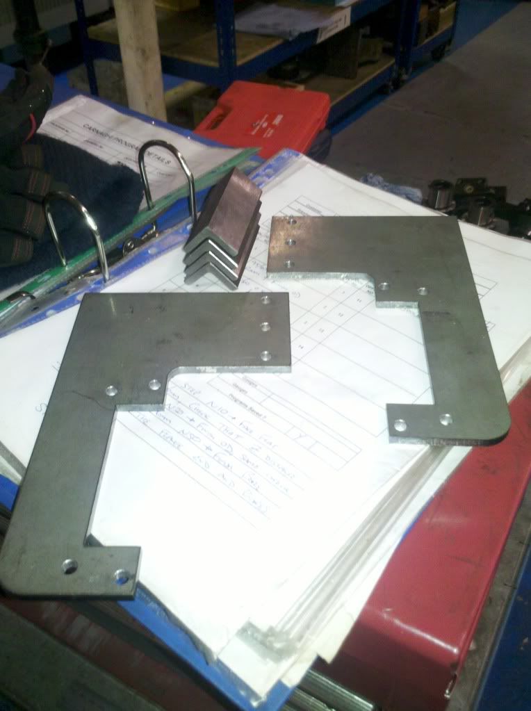 Because the engine has double acting cylinders, the con rods don't connect to the pistons like they do in an infernal commotion engine. Instead there is a piston rod connecting the piston to a crosshead, to which the conrod is connected. The crosshead is guided by the slidebars, which are supported on the end cylinder cover, and these motion brackets. I've also been to work for a couple of hours this afternoon to finish off the boring of the cranks. My method of making a fixture and then checking the centers proved unnecessary in the end, the centers having come out within 4 thou anyway. 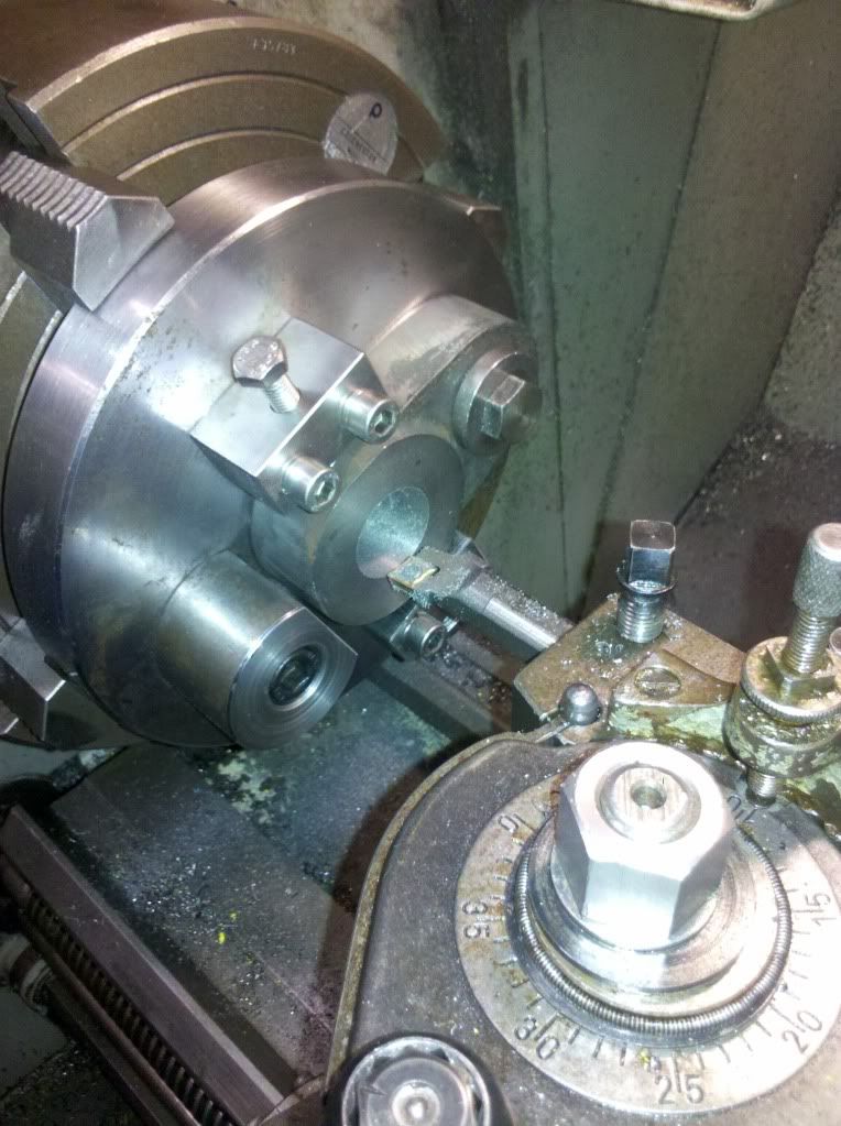 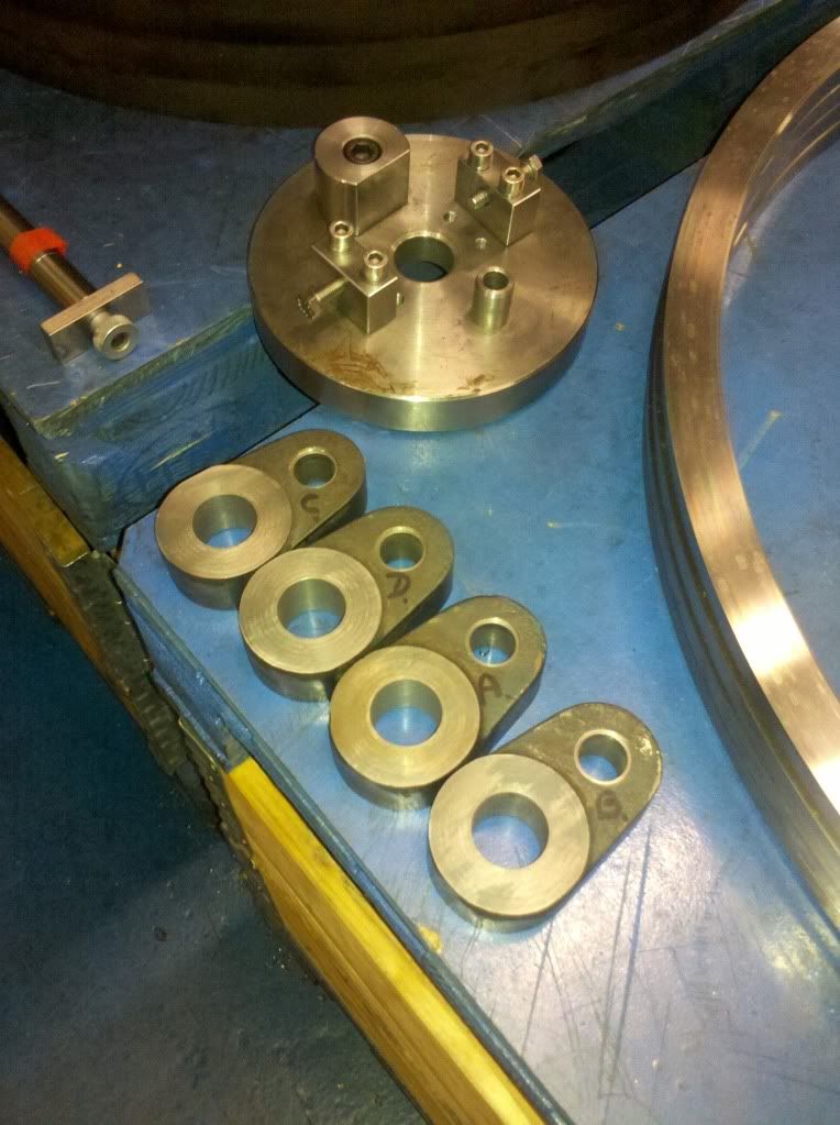 They are all now bored to be a light press on the axle. The next step is to fit the two driving wheels to the driving axle. Then they can be put between centers in the lathe, checking for true running, then finish turned ready for the tyres. For the cranks, I now need to make a fixture, or modify the turning fixture, so I can broach the driving keyways in. With the keyways cut I can then turn the crankpins to fit the cranks, press them in, scotch key them to make sure, and then fit them all to the axles. Once they're fitted, they'll get a shot blast and a coat of primer, before I shrink on the tyres, then a couple of coats of top coat to seal them in before I set them up in the lathe once more to finish turn the tyres. A final coat of paint will then see them ready for fitting of the valve eccentrics. The reason for painting before finishing the turning, while it might seem a bit backwards, is because Í will have to use coolant when i turn the tyres. The wheels being iron castings will absorb some of the coolant if not painted, which will then be difficult to overcome. While I'm finish turning the iron, I don't bother about coolant when its nearly to size. I do when I'm roughing, but as I've got closer to finishing the 'skin' of the casting that has absorbed the coolant gets machined away anyway. Fitted the keys and the driving wheels to the driving axle last night....we now have a pair! 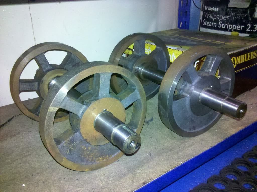 After sorting Kettles brakes this morning I've been down at work again. Now that wheels are on the axles, I've trued them up and skimmed all the faces, so everything is all square and true now, ready for fitting the tyres. 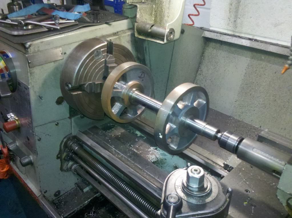 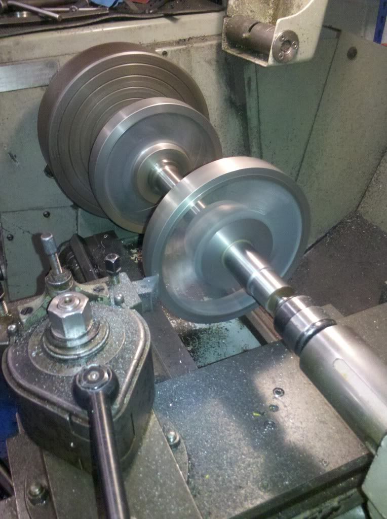 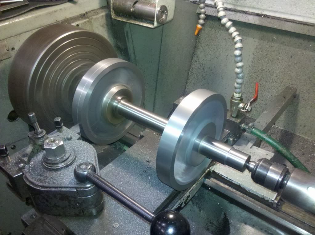 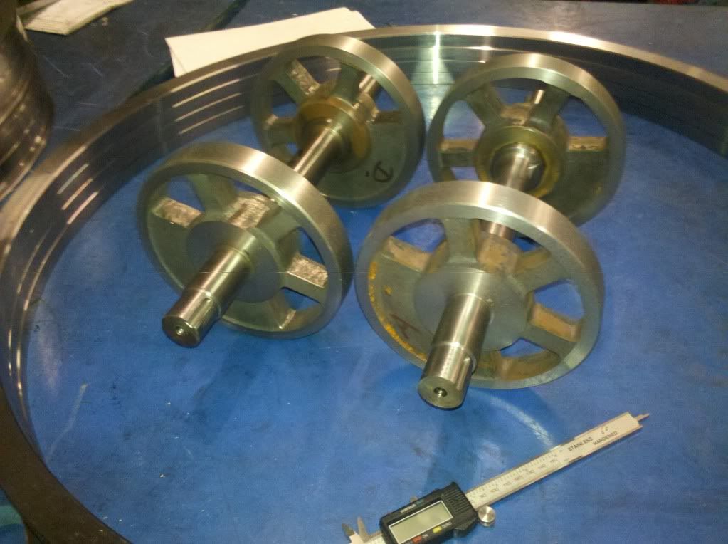 |
|
|
|
Post by ejparrott on Nov 10, 2013 12:54:17 GMT
I now have a broaching guide bush fitted to the fixture.... 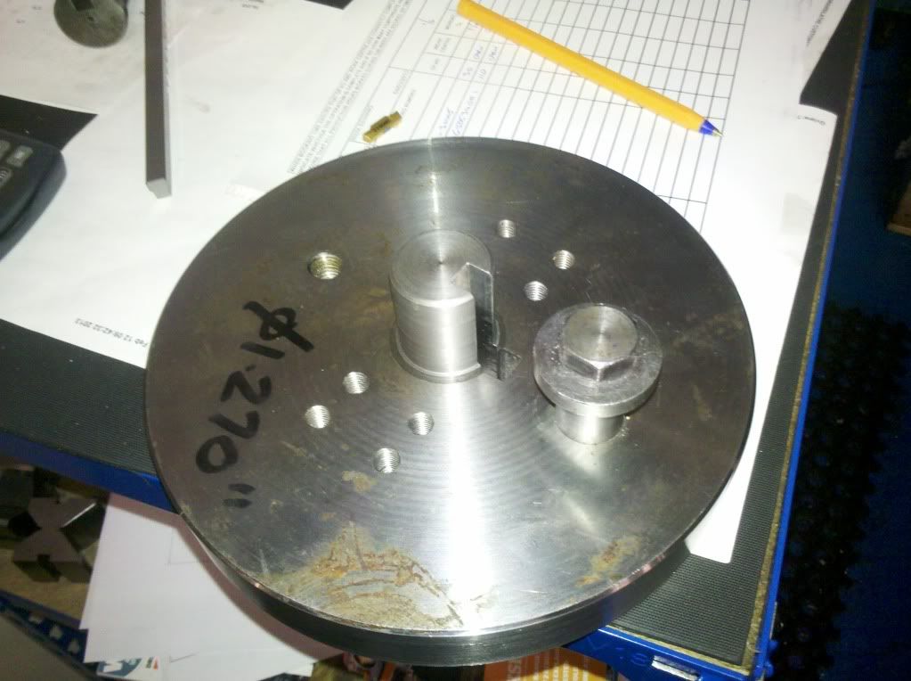 so the crank webs will be held all in the same position... 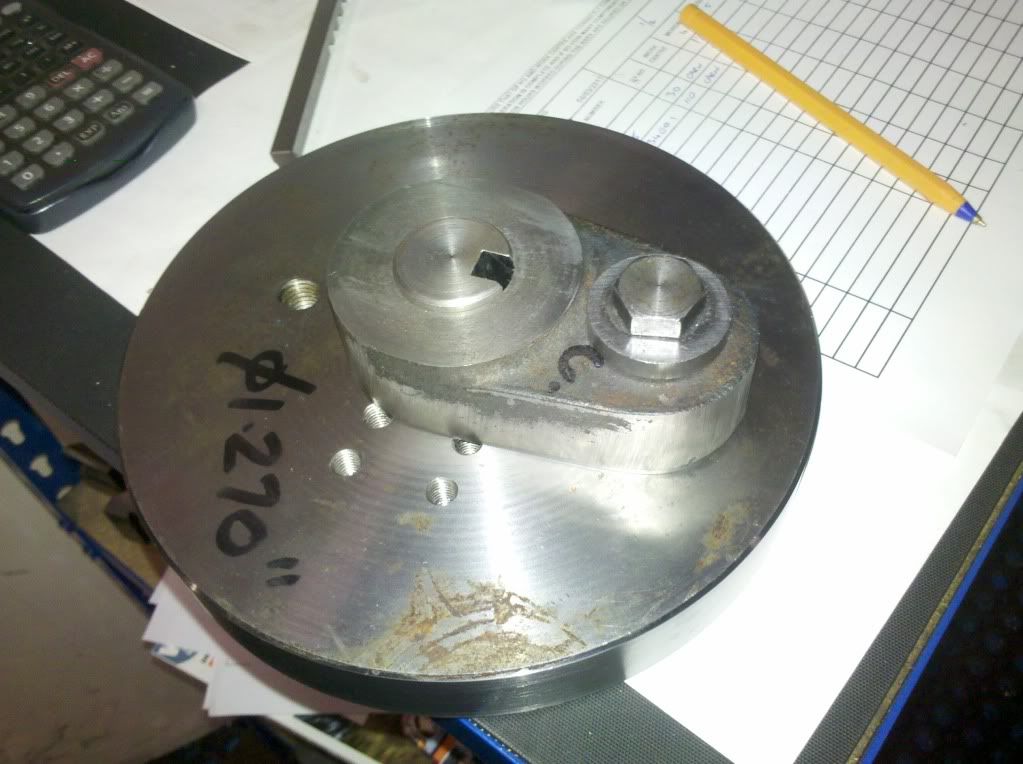 while I broach the 6mm keyways which will drive them on the axle.... 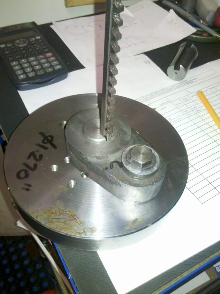 Broached the keyways now... 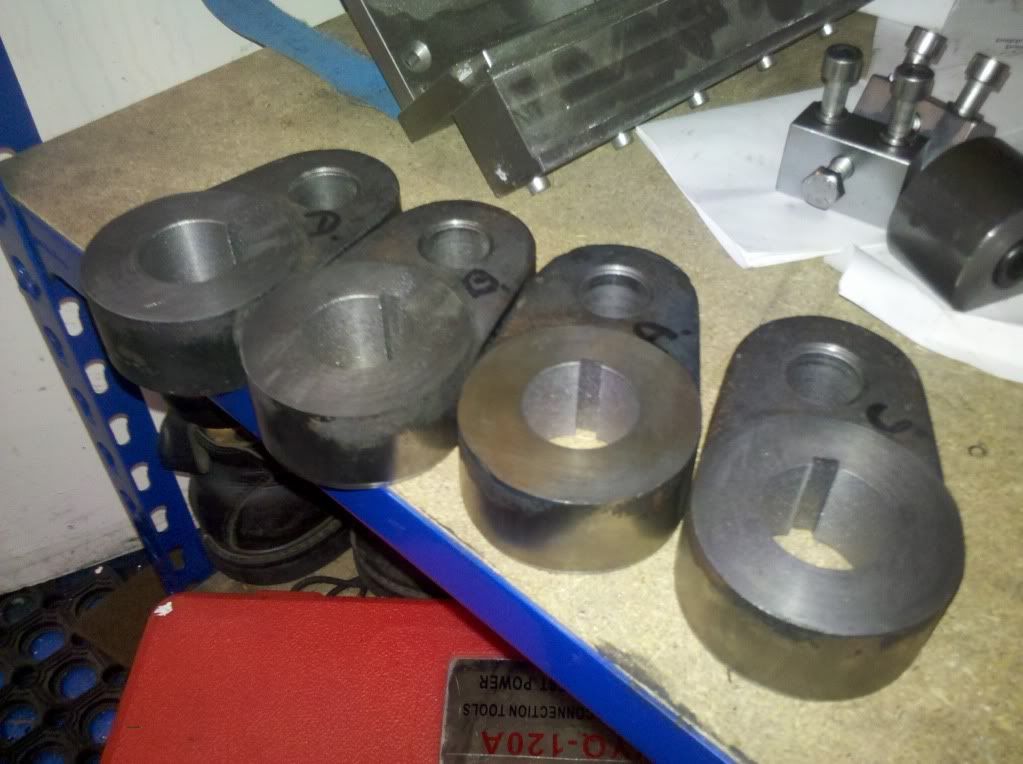 Robin, what was the name of that 7¼ railway? I'm thinking I'll be looking for a new track to run the Romulus and this on sometime soon. Had a parcel turn up from America yesterday, an elbow for the whistle valve to take the steam feed from inside the cab.... 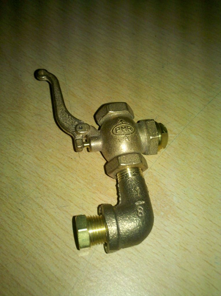 ...slightly awkward being 1/8NPT rather than BSP, but I'm a mcahinist by trade, if I can't deal with that there's something wrong. Besides, the fittings avliable from the UK suppliers are absolutly crap in comparison, and 1/4BSP is the smallest avaliable which I thought would be too big, and at 3 or 4 times the price, even when you allow for a $25 dollar shipping charge..... However....I tried it against the cab spectacle plate this afternoon.... 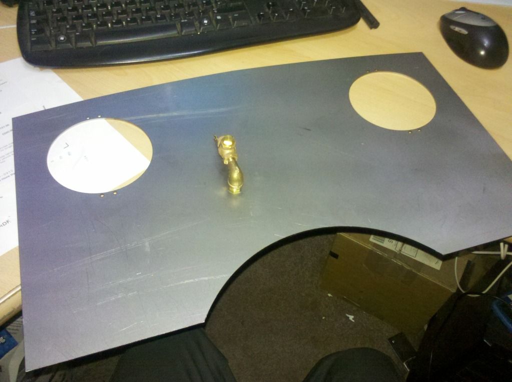 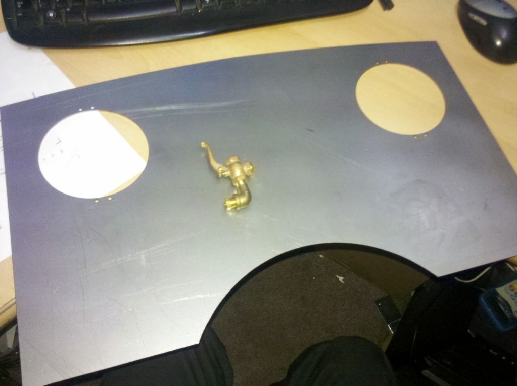 I think 1/4 would have fitted fine.....I keep forgetting how big this engine is going to be.... sh0ck |
|
|
|
Post by ejparrott on Nov 10, 2013 12:57:16 GMT
Also this week, I've machined the crankpins to fit the flycranks, and now pressed them in aswell... 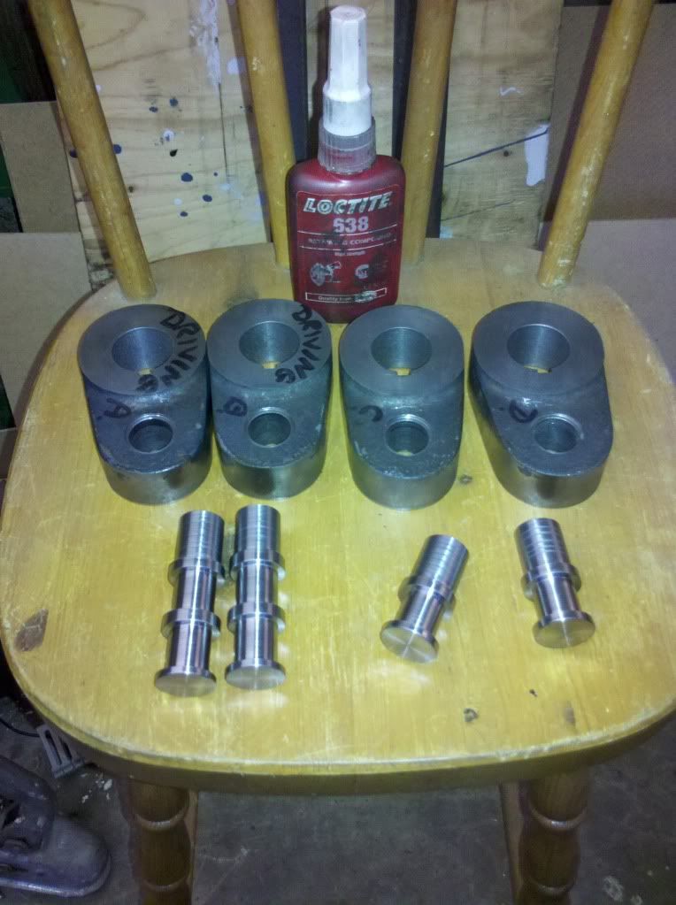 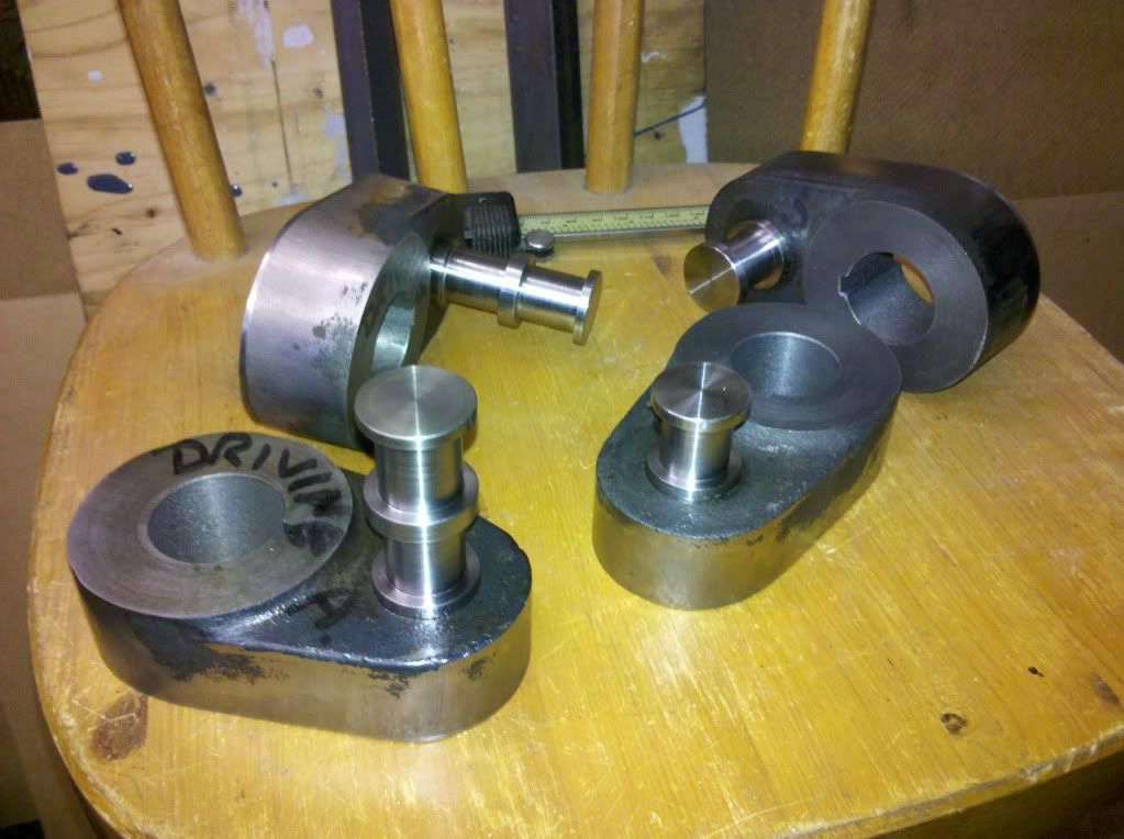 I'm hoping I can get them scotch keyed this week, and maybe even pressed on to the axles. That would be a good achievement. Popped in to my local sheet fabricators this week and got a couple of bits of angle folded up....  Top half of cab coming together. Other jobs this week, I've silver soldered the elbow for the whistle in to a piece of brass plate as a support, and today profiled it and cleaned it up.... 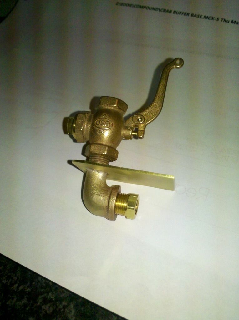 ..probably one of the last things I'll need to fit on the engine, but having to work on what I can until I clear space in the workshop, and get the lathe and mill back up and runing. I've also ground the backs of the motion brackets where Aubyn welded them for me. I'm now in possession of a set of boiler drawings for a John Milner 'Hunslet' engine in 7¼" gauge. The boiler is remarkably similar to Jubilee's. I need to go and visit the boiler maker and get his opinion on it, but I think a stretch of the barrel and the firebox, with an extra row of stays in each wall of the firebox, will see me with a suitable design...the downside is its all 3/16" thick copper = not cheap! I managed to get two of the flycranks scotch keyed this week, one for each axle.... 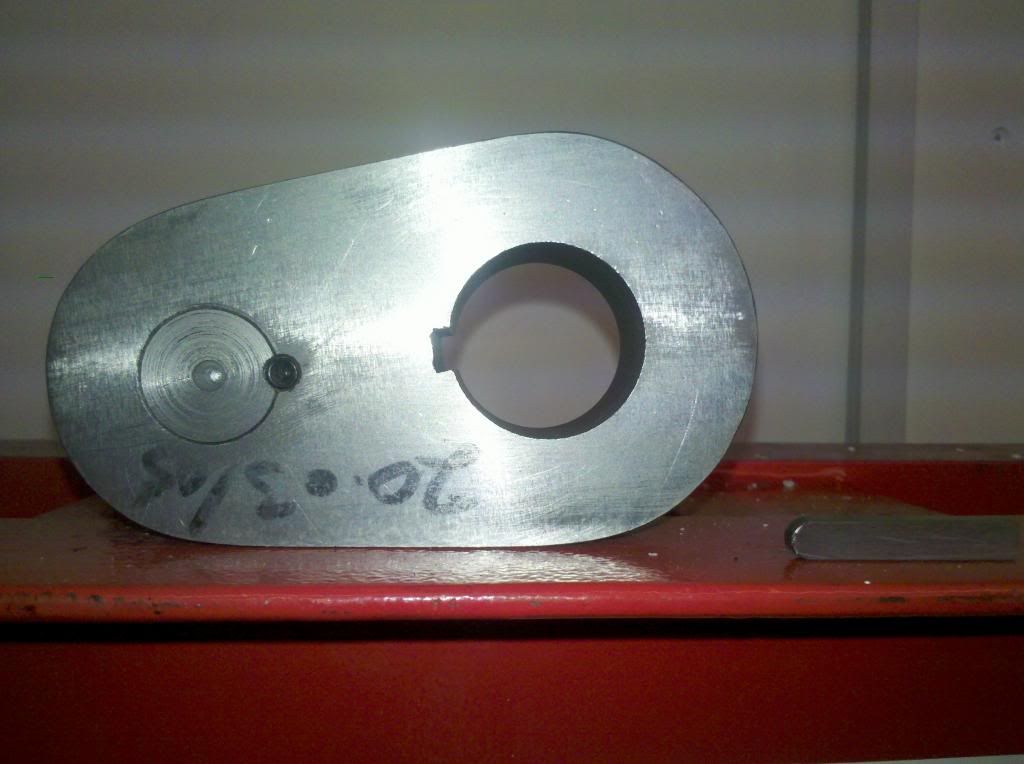 ...and then I got the keys fitted and pressed them on to the axle.... 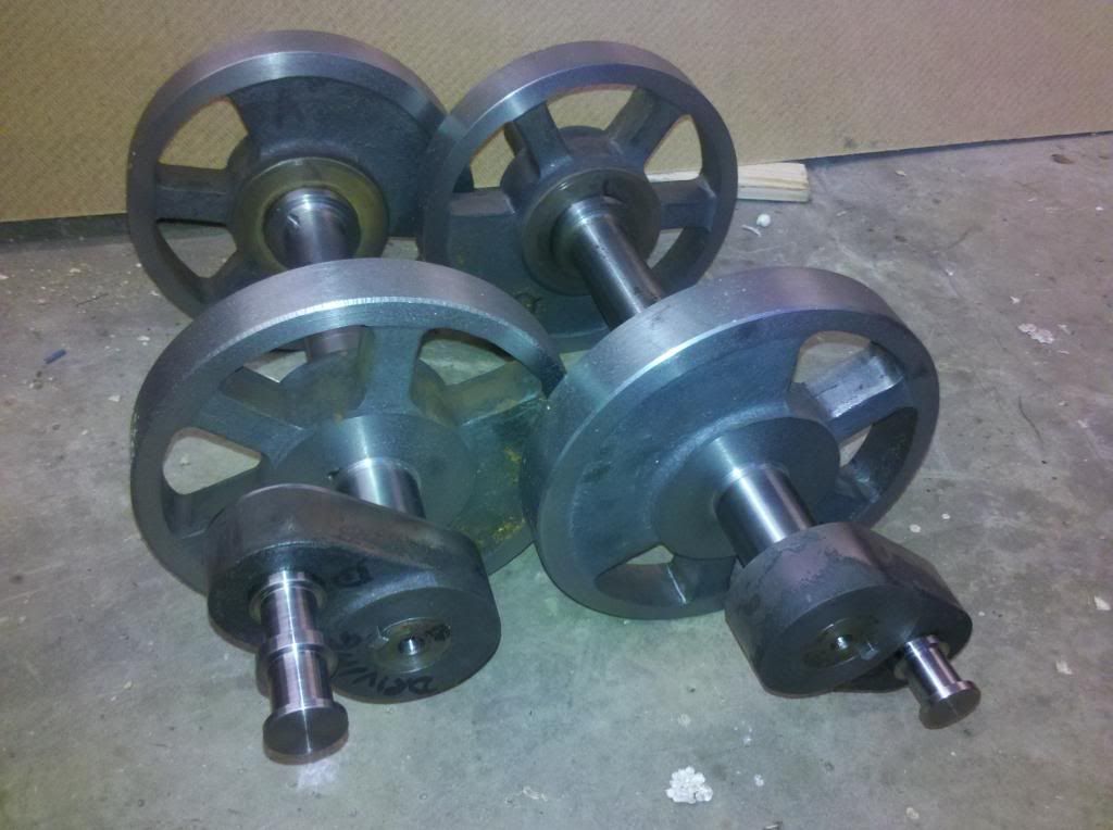 Really do need to get tyre material ordered now, as the next step is to get the tyres shrunk on ready for finish turning. I'll take these to work now and pop them in the grit blasting cabinet ready for a coat of primer while the tyres are roughed out. Love the new look Robin, much more to my taste! Strange that such staunch LMS man should have such a fancy for a Gresley whistle....and one that was an American import to start with! Anyway, a bit more work this week, I've been marking out the cab platework ready for fixings. I've decided on this engine I'm not going in 100% accuracy. With our Talyllyn engine, and my Hunslet, we have modeled all the oddities that are present on the fullsize. That means thinks like saddle tank support brackets where one is one way up, and the other is reversed, odd pitches of bolts are modelled, and even odd sized bolts. With Jubilee I've decided to use the right size scale bolts and rivets, but they are to roughly the right pitch, but possibly one or two short or over, and no odd pitches. This is intended to be a capable, heavy and regular performing engine, not a glass case model. I've already modified the valve gear so its just another small deviation. 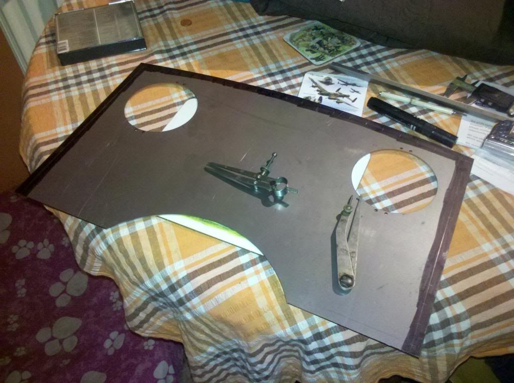 Yesterday I found a piece of brass bar to silver solder to the top of my whistle tube aswell, so thats coming along a bit too.... 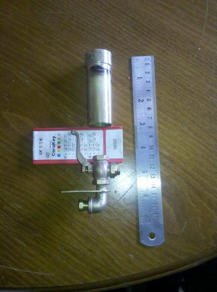 Having the afternoon off, I've also started forming the smokebox front and rear plate flanges. Normally, I would have made a flanging block, cut the plates over size, and beaten them over, same as copper boiler plates. Thought I'd try something different this time and weld a strip to the plates instead. I have to be careful because the smokebox is a close fit between the frames, so if they were flanged over size or the wrapper was over thick, I'd be in trouble. Either way could result in disastor if I'm honest, as the front plate of the smokebox has no thickening ring around where the door closes, and on a steam engine its imperative thats this seals properly, otherwise the engine won't steam properly. Any twist built in at flanging or welding is going to cause problems, so I'll have to be careful. If it does go pear shaped then I'll have to sort something out later, fit the thickening ring it wasn't built with. Lilla has one, and we have no problems with her. I suspect if there had been problems with the real one they wouldn't have worried much, or they'd have bunged a bit of fire clay in and not opened it more than once a week. Although she was a 'main line engine', she's still a quarry engine, not a crack express locomotive. 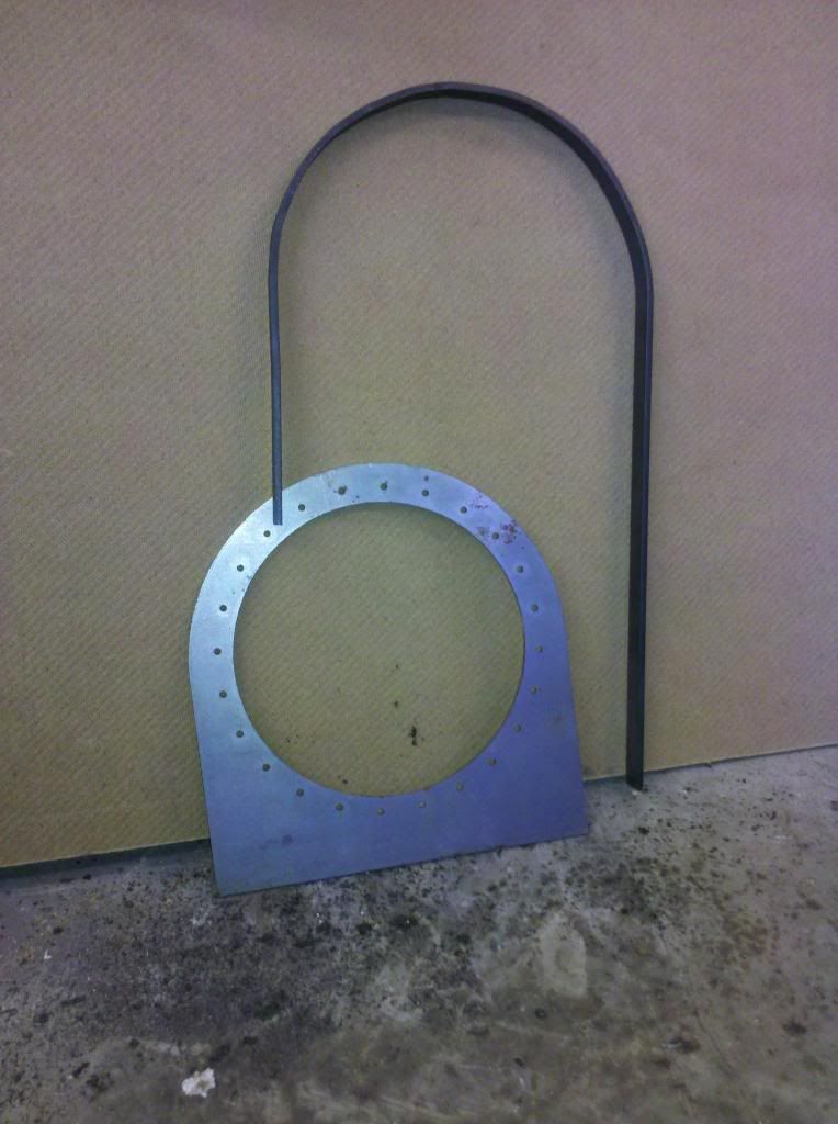 Anyway, first off I've got to finish modyfing my welder, only I've lost the realy for the gas valve, so I'm a bit stuffed! |
|
|
|
Post by ejparrott on Nov 10, 2013 12:59:25 GMT
I spent yesterday at a friends machining the chimney base on his 3-axis CNC Bridgeport clone. Had a lot of problems getting it going, struggling with tool lengths and vibration and programming, but cracked it in the end. Started with this.... to become... 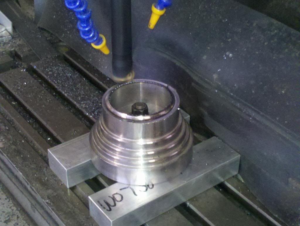 and when I left last night... 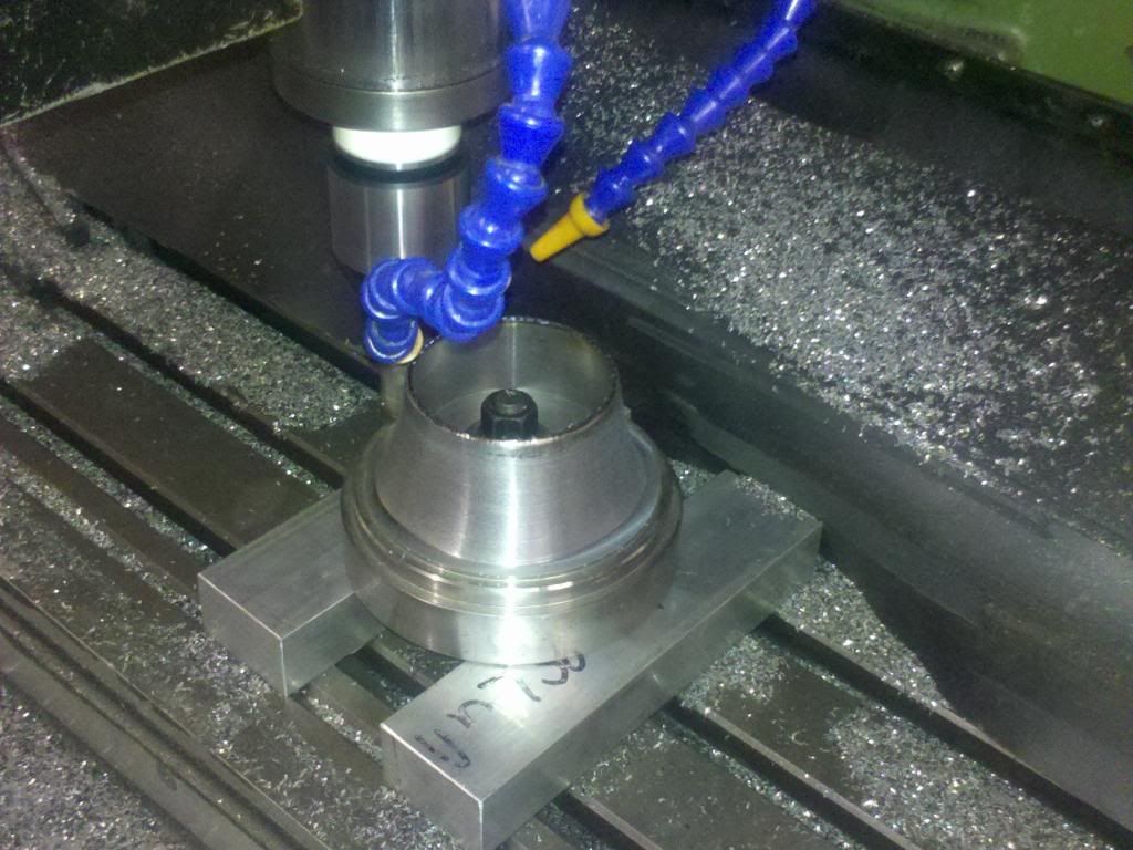 The outside is all now done, so I'm told, and we can turn it over to do the bottom face where it joins to the smokebox. Holly's been busy drilling cab plates for rivets too... 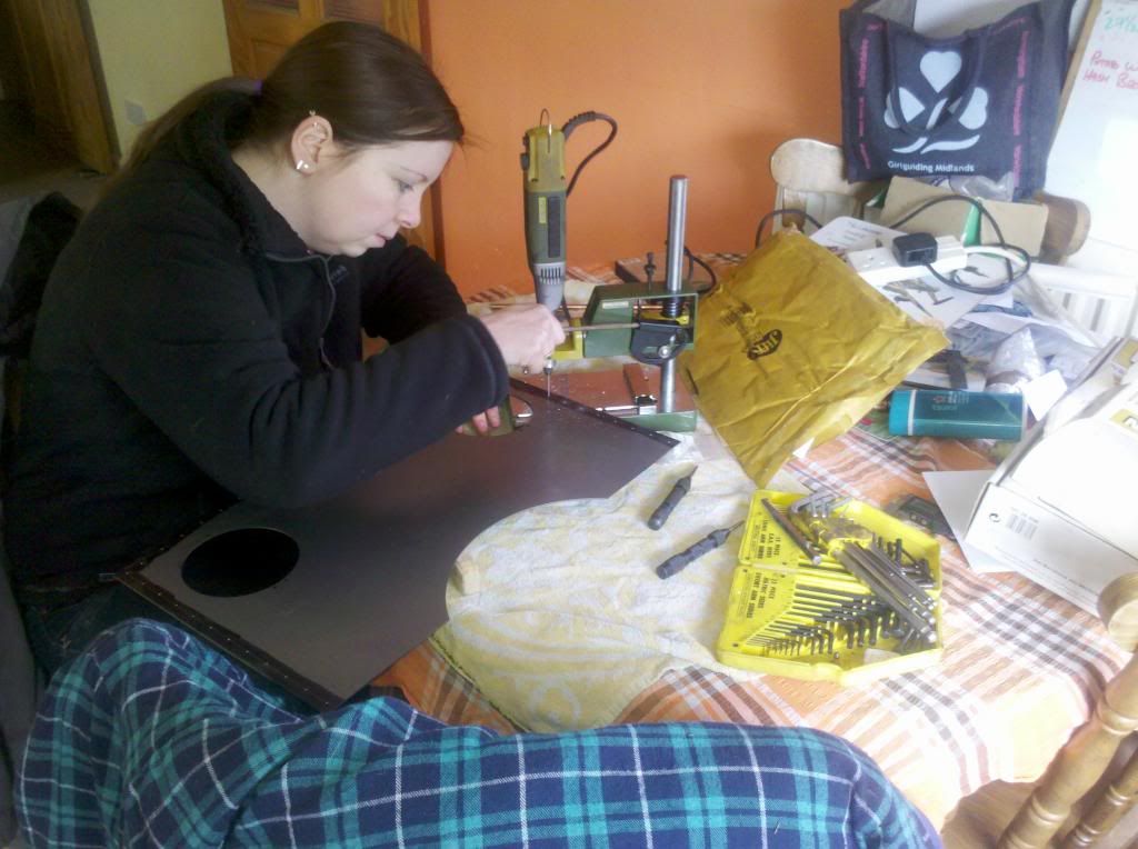 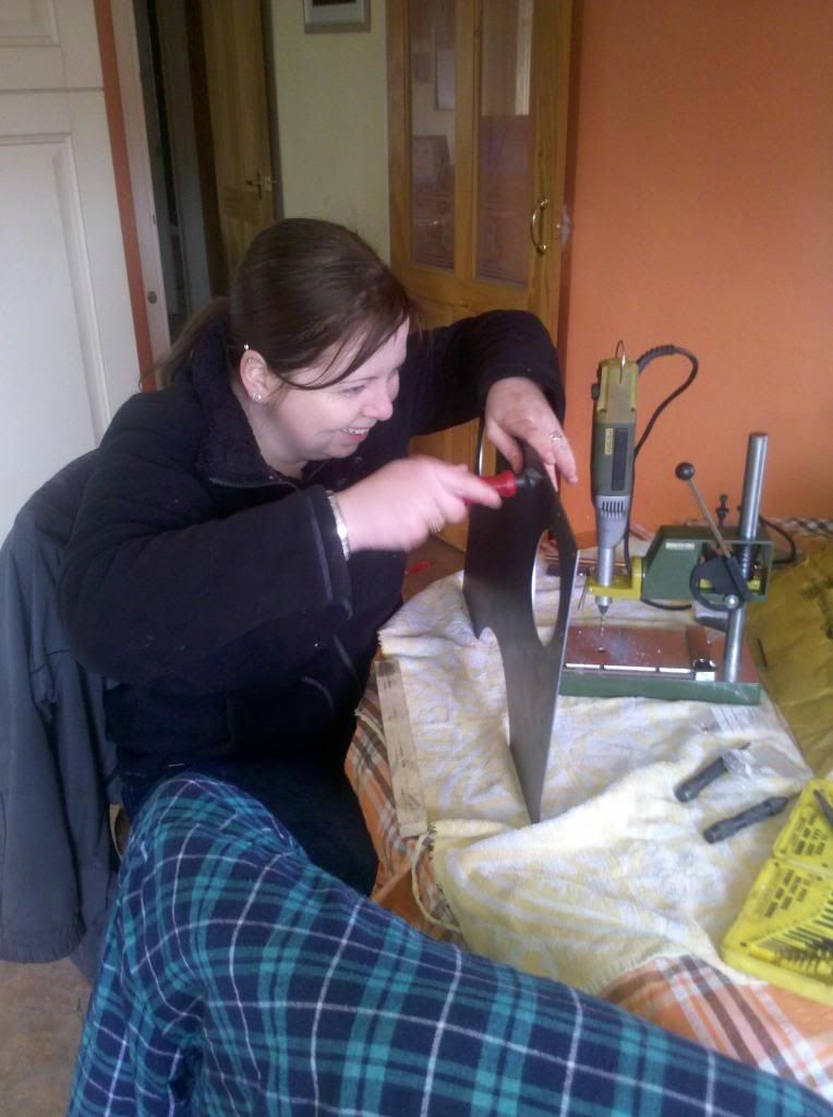 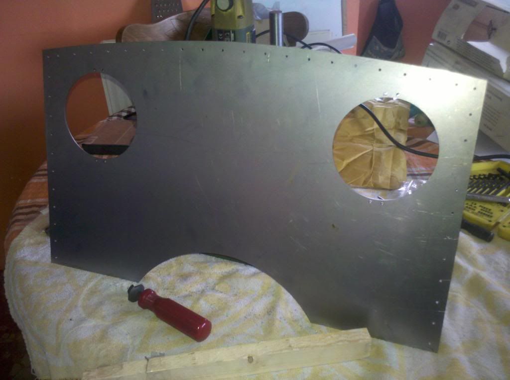 Latest delivery from the Laser Cutters, sections to make up the curved angles and T section that support the roof, and the parts to make the slidebar brackets.... 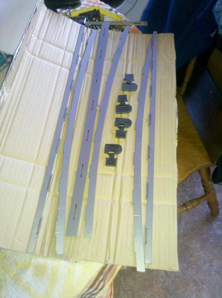 I've just dropped the angle and tee sections up to the sheet metal workers just up the road and they're going to TIG them together for me. I've also shot blast the slidebar brackets, and separated the first set to try the fit.... I'll keep the rest together for the time being, and when Aubyn's made me a brazing hearth I'll silver solder them all together... 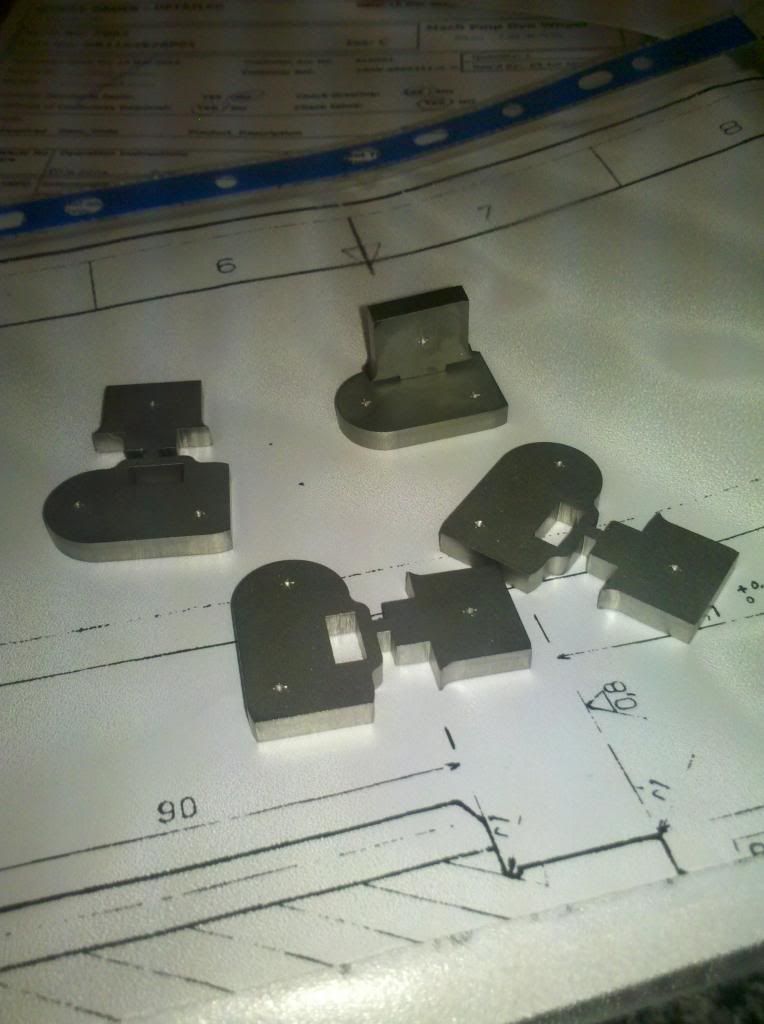 Having found them closed when I finished work yesterday, the sheet metal workers happened to be open when I went past this morning, so I called in to see if they'd done my welding. They hadn't, but they got right down to it there and then, and promptly made the job of TIG-ing 1.5mm steel together look easy! 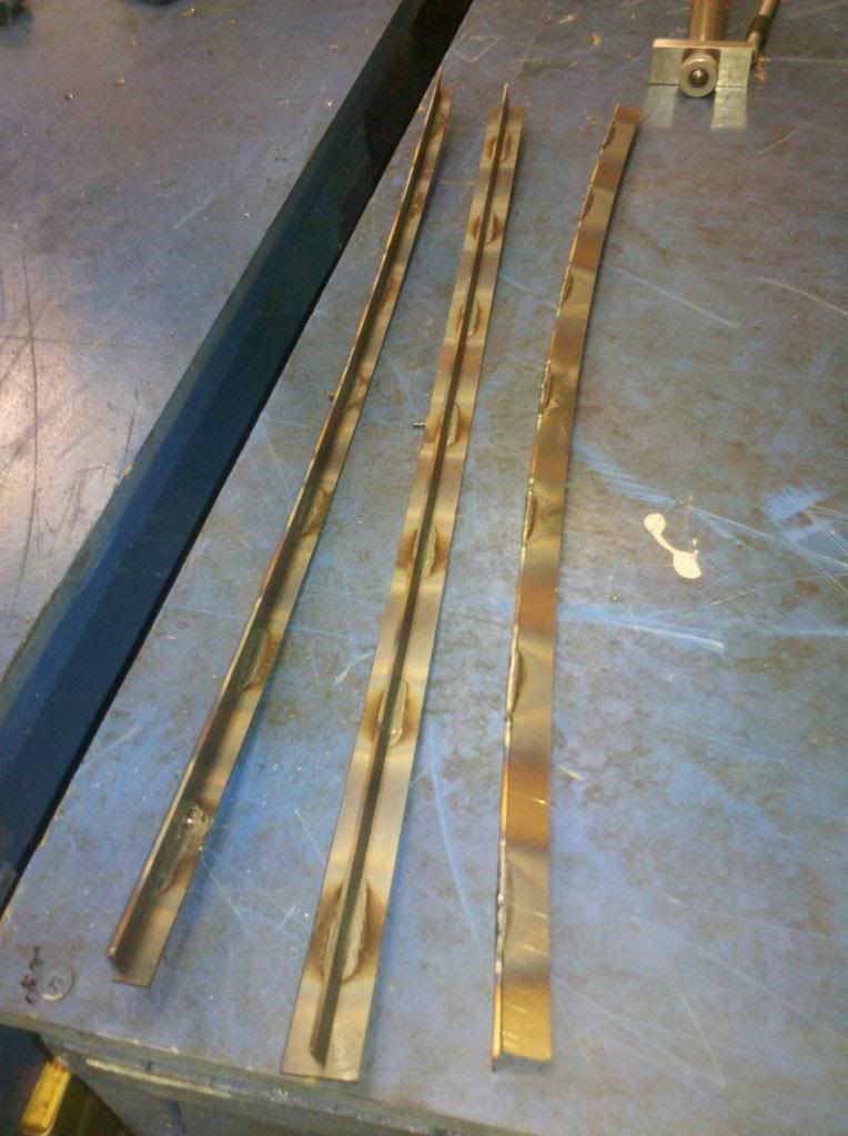 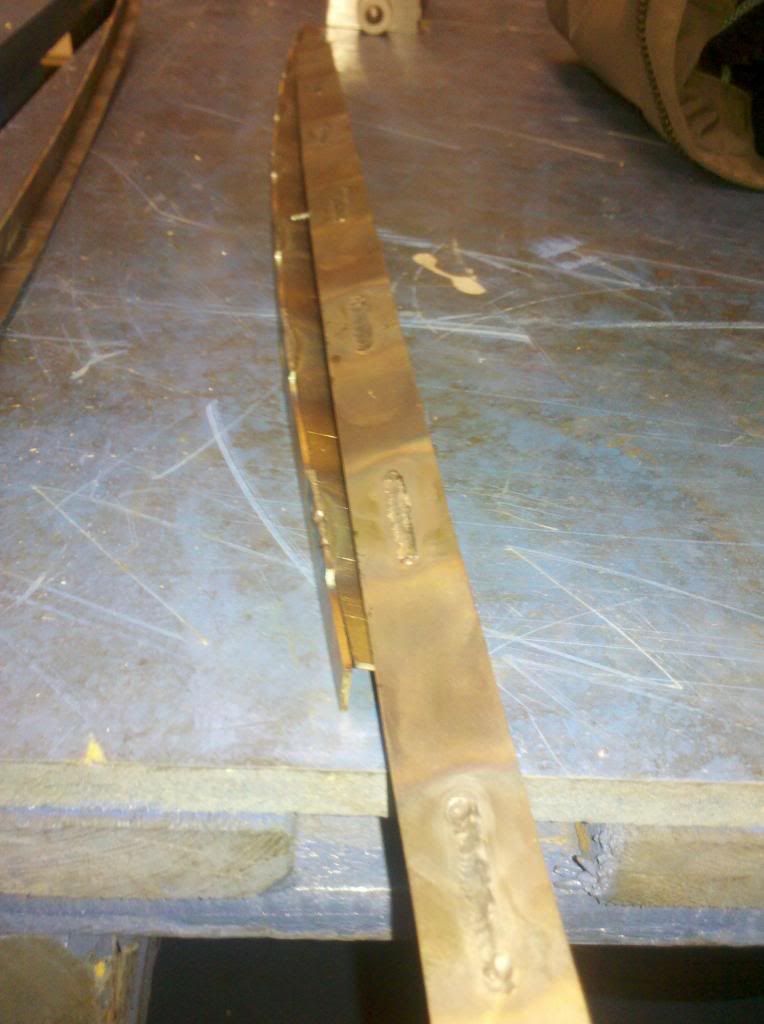 A little work with a grinder and the works shotblaster, and they look real nice now.... 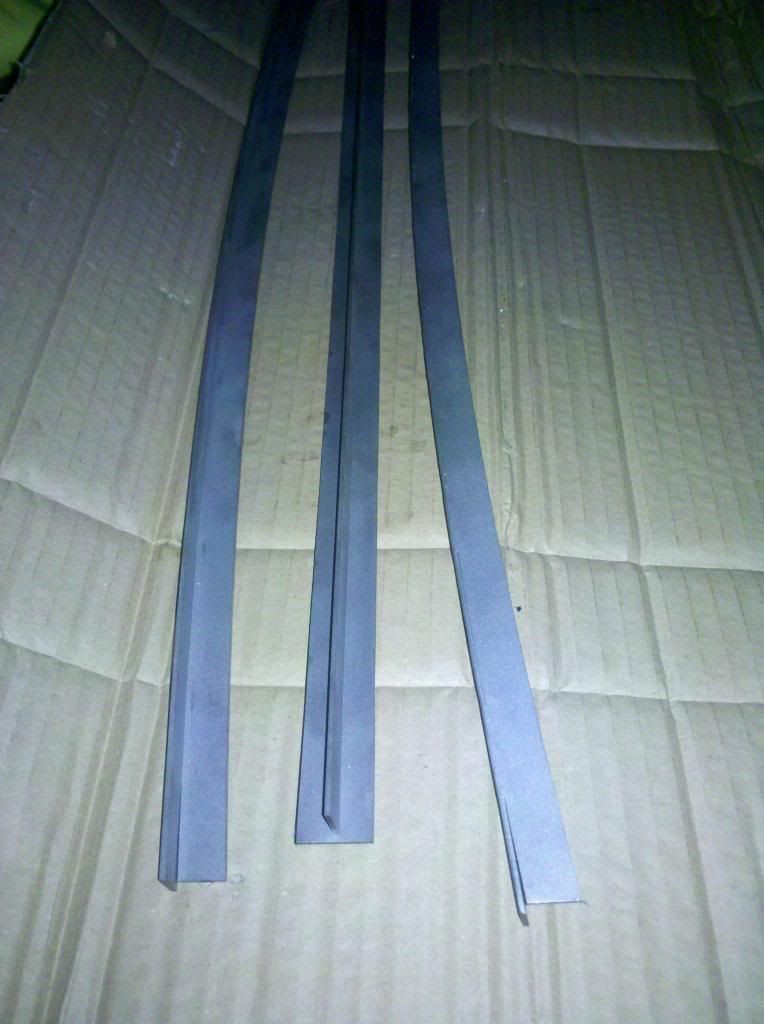 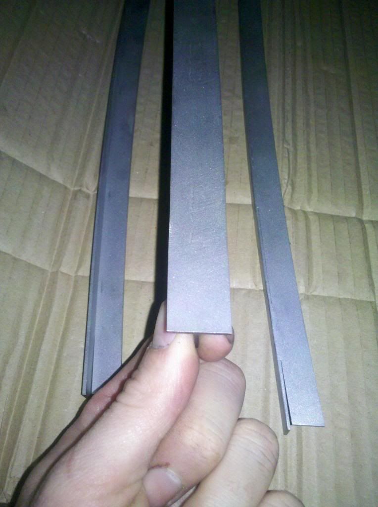 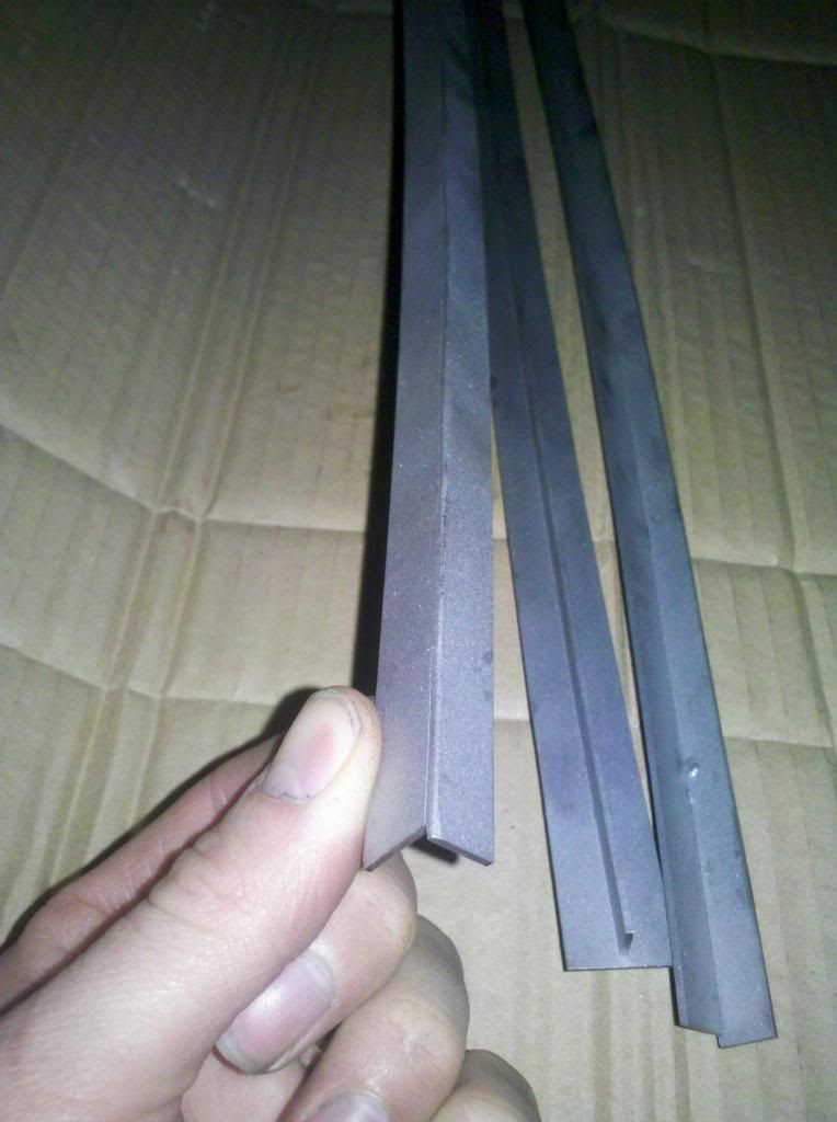 By the time they're rivetted in the cab roof, I very much doubt anyone will notice them for what they are, but they'll do the job nicely. I've also had the radius turned on the top bell of the whistle, and this morning I drilled and tapped the hole for the centre post, just need to order a brass dome nut to top it off now, although I may need to adjust the height of the bell to 'sound' it, but that'll have to wait until I can test it on steam.... 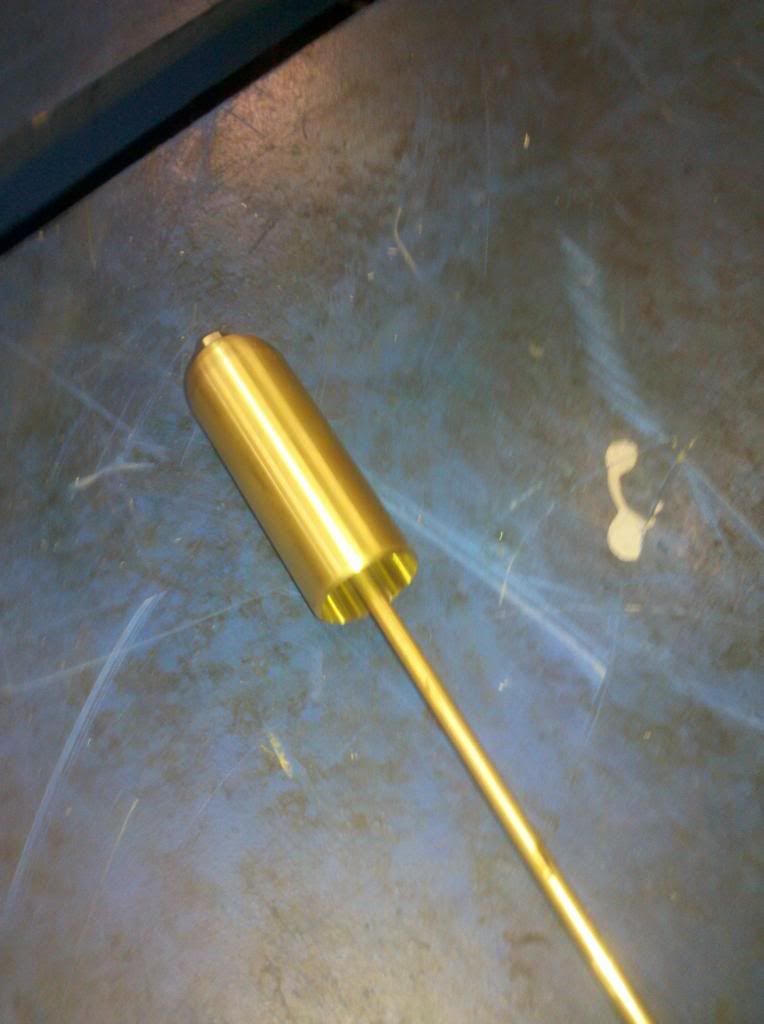 |
|
|
|
Post by ejparrott on Nov 10, 2013 13:00:52 GMT
My friend finished off the base of the chimney on his mill last weekend and delivered it to the club yesterday morning.....couldn't resist so popped down to work to finish it off, and then pressed it on to the tube.... 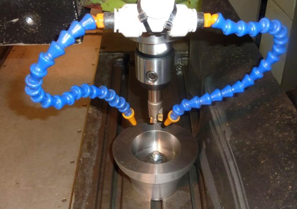 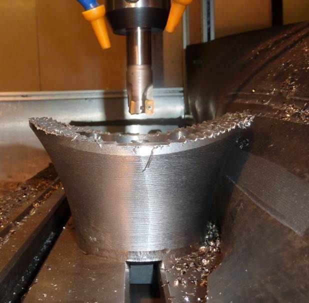 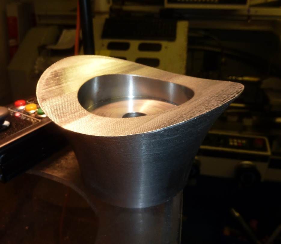 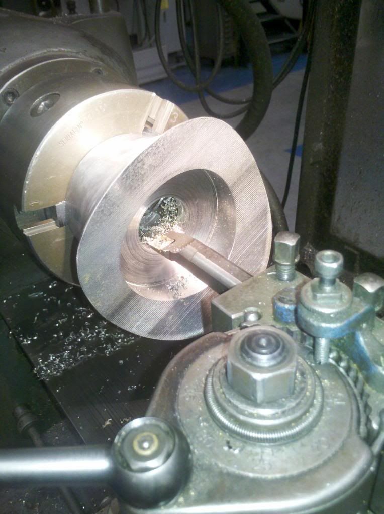 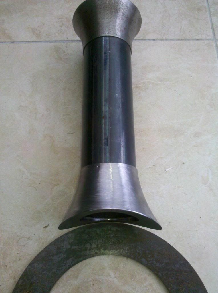 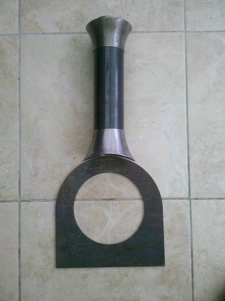 Now that the welder is back in action I've also started welding up the rear plate for the smokebox. I've got to be careful not to do too much in one heat, put too much heat in, and twist it out of flat. It'll probably be Thursday before this side is finished, then I'll start on the front plate. Lots of work for the grinder then, before rolling the outer wrapper and rivetting together, finally fitting the chimney to crown it all. 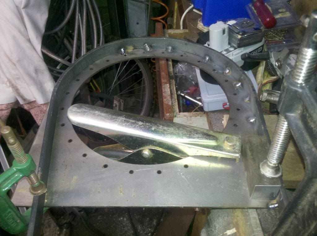 Progress slowed a little this week while working on one of the clubs engines, however my friend David did a little bit of CNC turning for me and produced the base for the whistle.... 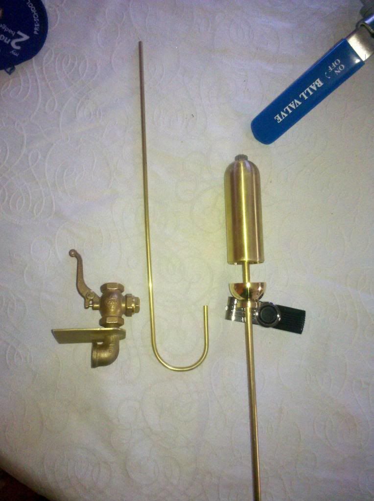 I've also bent the brass tube to form the beading for the shelf that it sits on, just need to split it now, and solder it on. I have done some work on the smokebox plates too, the back plate is fully welded and I roughed out the corners, I need to set it out on the workmate so I can get a proper look at it, but its looking pretty good so far - and its still flat! I've been thinking about having a painting done, Jubilee and Lilla together at Cilgwyn or Penrhyn....I'll bear it in mind. Got up early today...forgot to alter my alarm censored so I've made some more bits.... The cross-heads are quite large, and don't lend themselves to being made in one piece.... 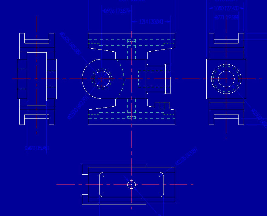 I turned the centers this morning, with reamed hole for the piston rod, next step will be to mill the bodies square, radius the ends, put the little end pin hole in, and then mill the slot out for the little end of the connecting rod....when I've got a mill available..... 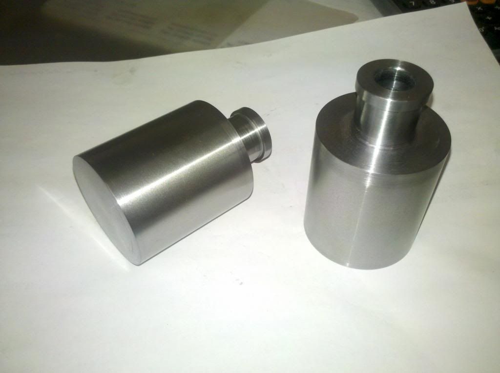 |
|
|
|
Post by ejparrott on Nov 10, 2013 13:02:16 GMT
Having a bit of time spare this morning, I've also turned the hand brake column.... 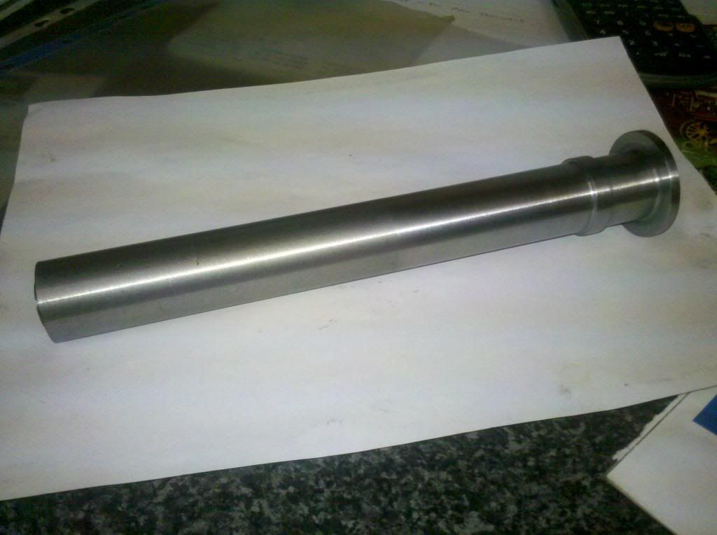 Thats another job to join the milling pile.....need to flash the bottom off at 5 degrees, and then fit the square foot to it....I'll either silver solder it or have it TIG welded....unless it takes so long to get the mill up and running that I've done my TIG welding course before its ready, and then I'll TIG it myself! Bit of success yesterday. The handbrake screw is a 1/2" square thread with matching nut. Now, square threads are an absolute female dog to cut and I really can't be arsed....ACME threads were developed to make it easier, especially for CNC's, and have a 29degree taper, but again, a pig to cut without the proper gear, 1/2" females especially. As luck would have it, good ol' fleabay turned up a 12mm trapezoidal leadscrew with 3mm pitch, a four inch length for £1.60....I couldn't buy the material for that! Its soft as well, so I'll drill a hole up the middle and silver solder it to the main bit of shaft, and instant handbrake screw. Ok it's still not square, but you'll hardly tell anyway. Popped round to Valetree dinner time in the hope that they'd rolled the material to make the flange on the smokebox front.... They'd not only rolled it but welded it for me too...bonus! So now I have front and rear just in need of tarting up on the radius', and then they're ready for fitting the wrapper. While thats been happening, I've also been painting the chimney....was hoping that'd be done today but I've got a bloody bug in it 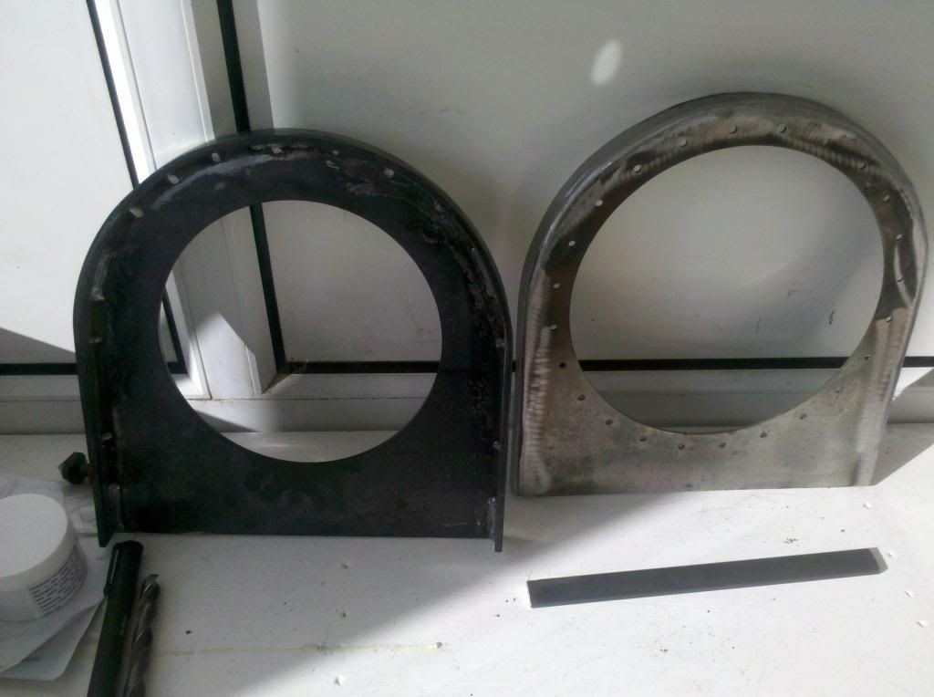 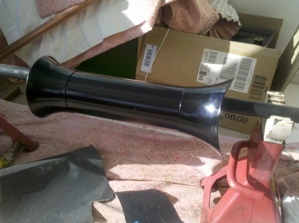 I think I've got a decent coat of paint on it now....maybe a Luna hair or two but no flies for sure. I'll leave it to cure in the conservatory for a few days which should be getting over 30degrees in there over the next few days. I'll get moving on finishing the smokebox shortly, then I can mount the chimney, and I'll give it all a once over again to make sure. Brake screw arrived yesterday too...just need to arrange some material for the main shaft now.... 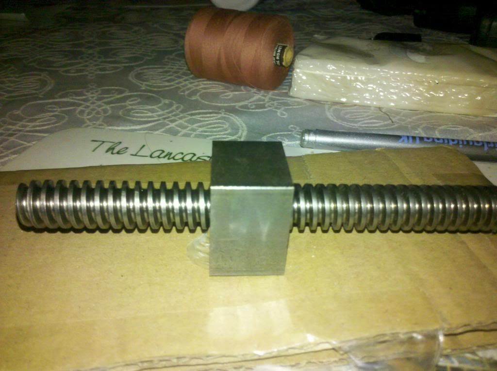 Packed the column off tonight to have its bottom milled off at 5 degrees too, then I can see about making the flange / base for it, fitting it together, and then concentrate on getting the bush and cap made for the top of it. |
|
|
|
Post by ejparrott on Nov 10, 2013 13:04:22 GMT
Not much happening, just toooo busy with far too many things happening. I've been and fetched the main frames out of store, and we've discovered that the engine'll be as long as Holly is tall.... 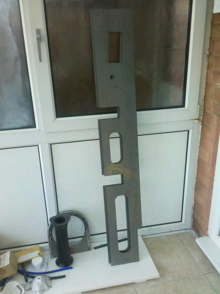 I had these laser cut 4 or 5 years ago, but there's been no space for me to assemble them so they've been in store. All the bolt holes are spotted with the laser, I need to go round and center punch them all and drill them out. Following on from turning the middle bits for the crossheads... 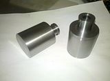 I managed to get some time on the EDM wire cut last week, and cut the top and bottom parts for the fabrication...took 2 days - the wire broke part way through.... 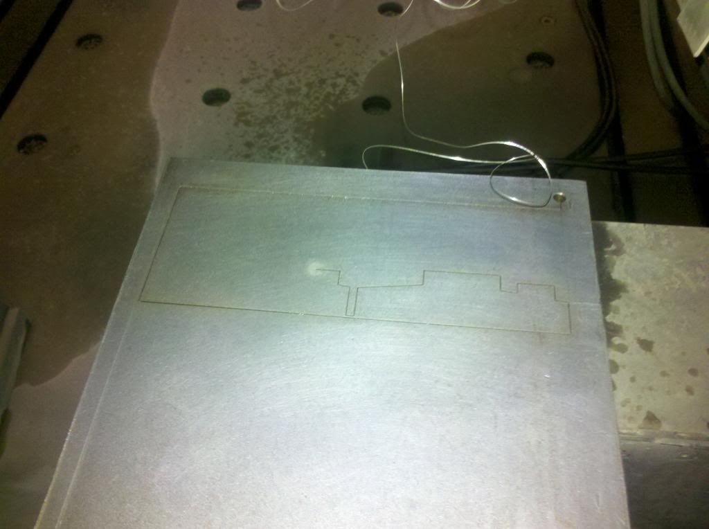 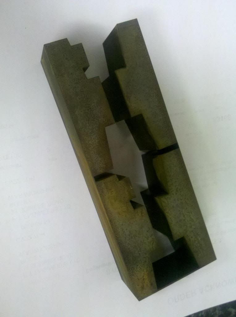 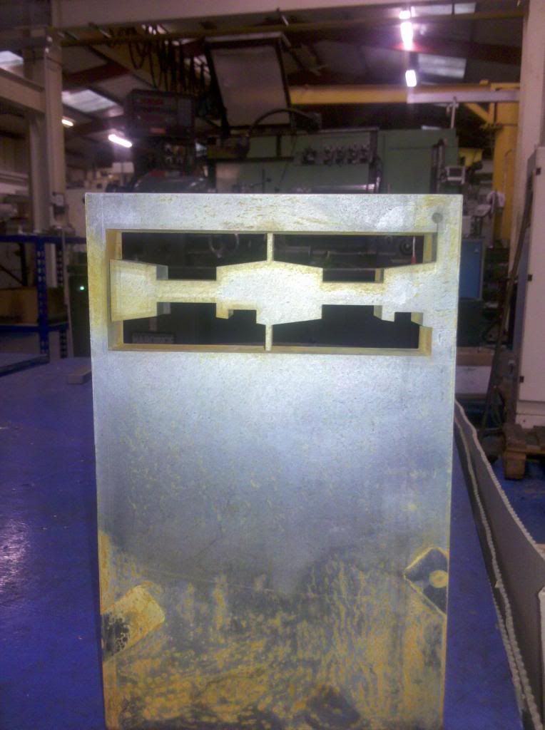 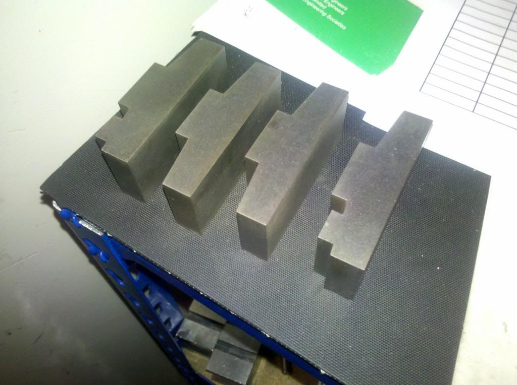 I've got to take 10thou off the joint face and drill some holes for fitted pins, to hold everything together while I silver solder it all together...of course first I need to get my mill up and running so I can mill the middle's.... Had an hour available on Friday so I finished off the assembly of the whistle. Turned the remaining part of the body, and then silver soldered it all together.... 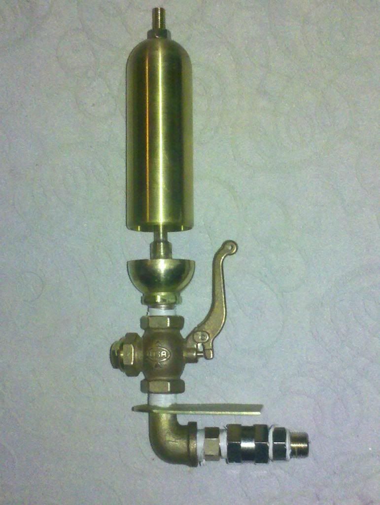 Put it on the compressor last night for tuning...damn near deafened myself! Decided to trial one of the motion bracket fabrications last night... 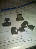 Silver soldered together... 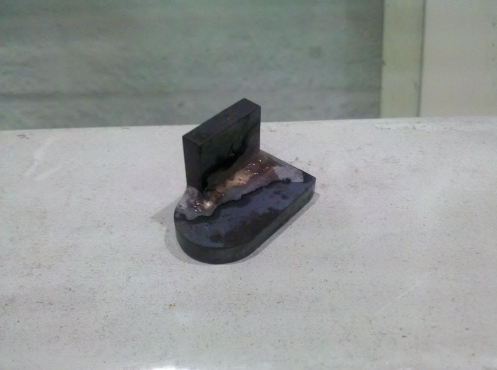 and then shot blast this morning, should be a good representation of a casting when painted.... 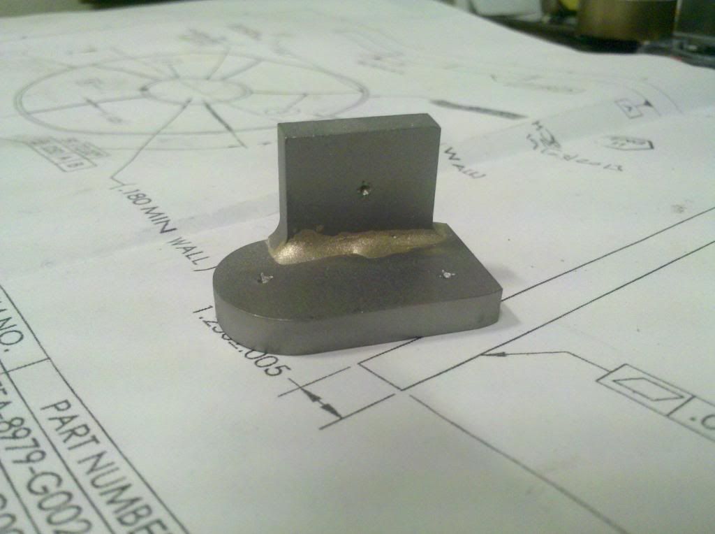 3 more, not the same now! Paid a visit to my friendly TIG welder today, had the mounting flange welded on to the brake column.... 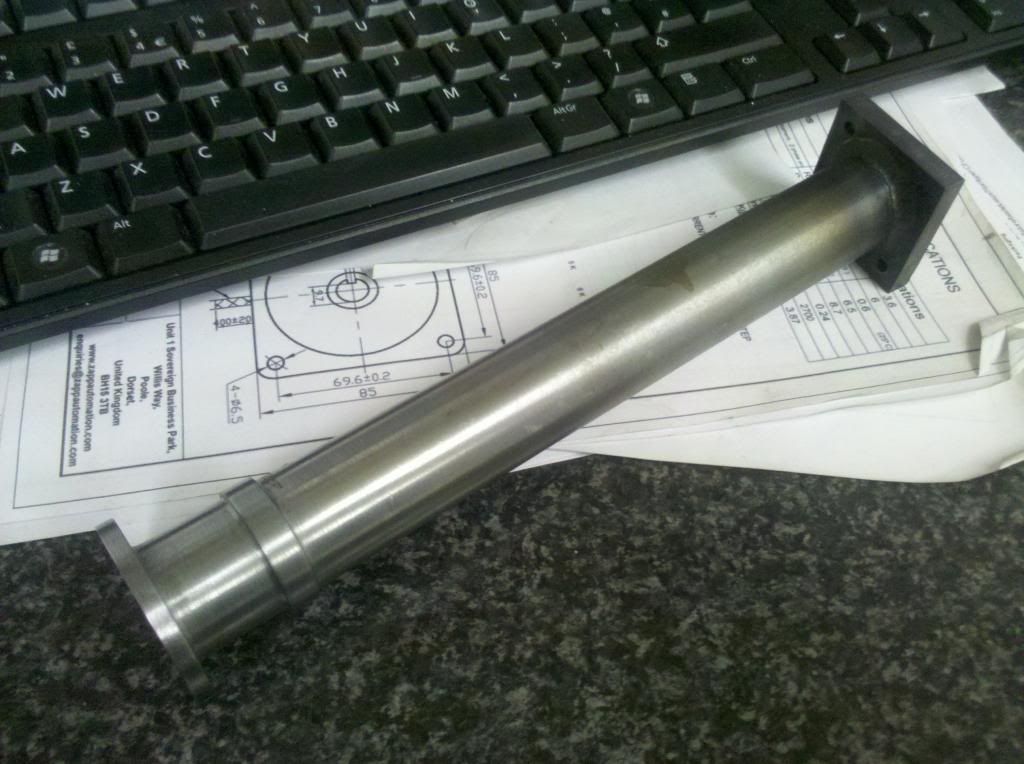 Shot blast and prime tomorrow, keep the rust at bay until I've got the top cap and the shaft made. |
|
|
|
Post by ejparrott on Nov 10, 2013 13:06:11 GMT
Got in the workshop for half an hour last night and silver soldered the remaining slidebar brackets together...shot blast them this morning along with the brake column.... 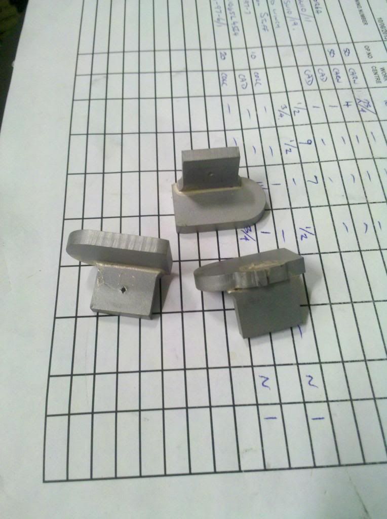 I am still doing odd bits but I've been stupidly busy of late so not much progress... Finished brake column got a coat of paint.... 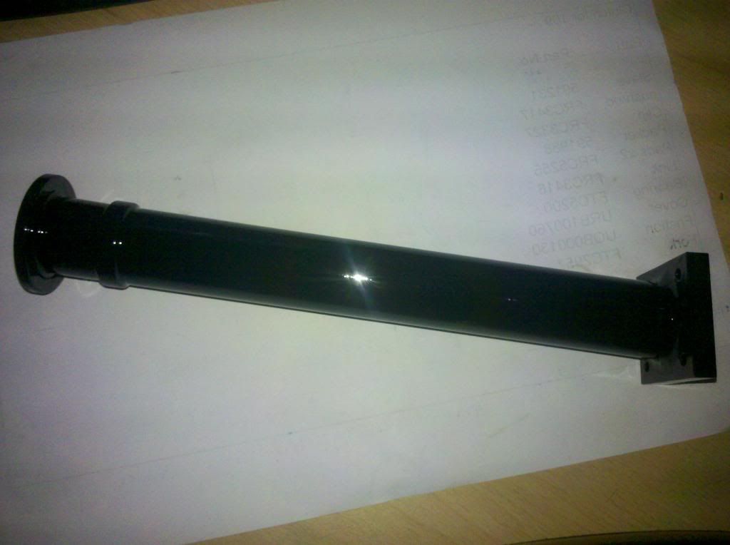 and Holly and I have started riveting the buffer beam to frame angles to the buffer beams, ready for starting to put the chassis together jawdrop 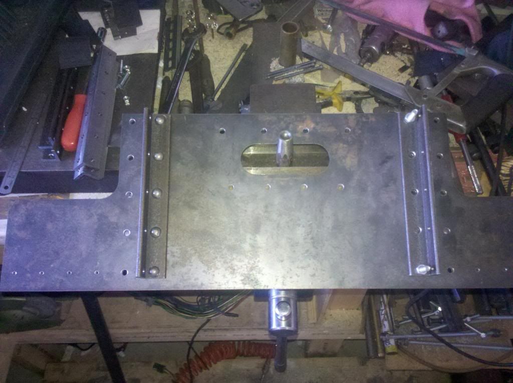 More impressive is the rate of things moving onwards  Maybe to you..not to me... What's most annoying is that I know I'm capable of building the engine at 20 times the speed its going at, and once I get the workshop sorted that's likely to be the case, but without the workshop available, its dragging! Popped down to my friends work and we did some work on the angles that are riveted to the buffer beams above and below the centre coupler.... 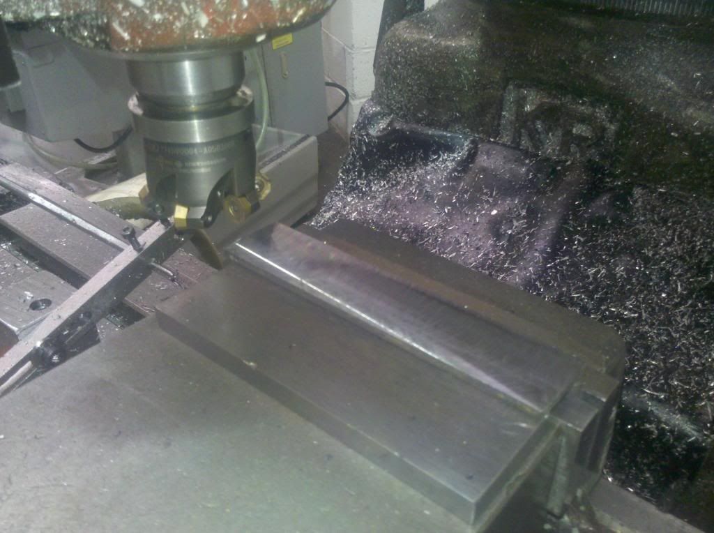 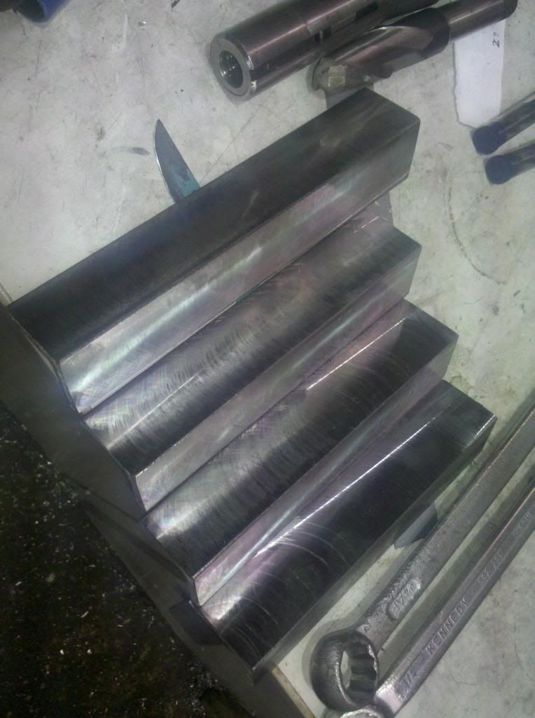 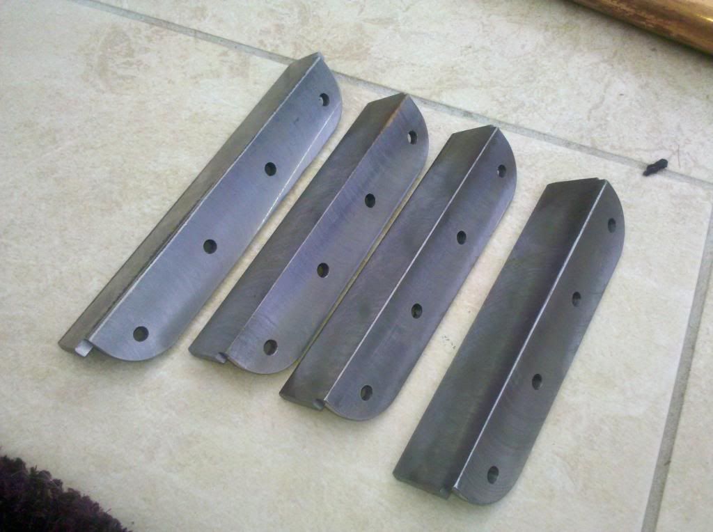 I need to profile the other leg now to the same shape, but there are no holes in it. Quick shot blast and then they'll be ready for riveting to the buffer beams as well.....starting to think I might need some more rivets.... After the busy day Saturday, David and I couldn't resist putting the frames and buffer beams together.... bugger me she's going to be big!!!! 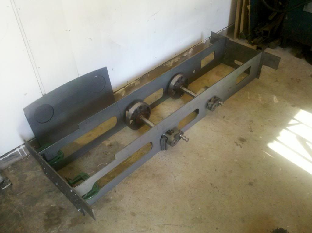 Went to work early this morning trepanned the first side out of the tyre blanks...what you see here is an hours work....still lots to go! Bet you're glad you don't have to do this with land rovers!! 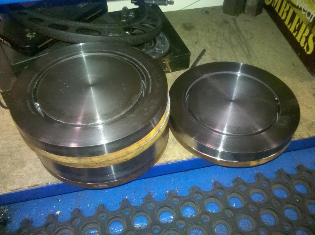 |
|
|
|
Post by ejparrott on Nov 10, 2013 13:07:46 GMT
2 1/2 hours and £70 later.....4 tyre blanks.... 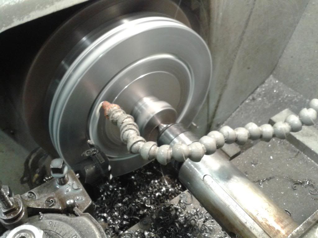 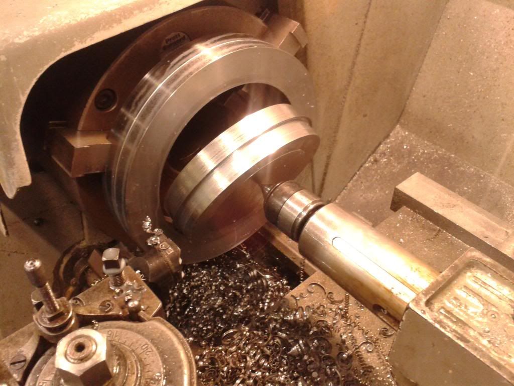 4 free bits of material s_clap s_clap 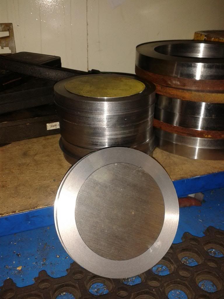 Then a couple of hours stress relieveing at 680.... 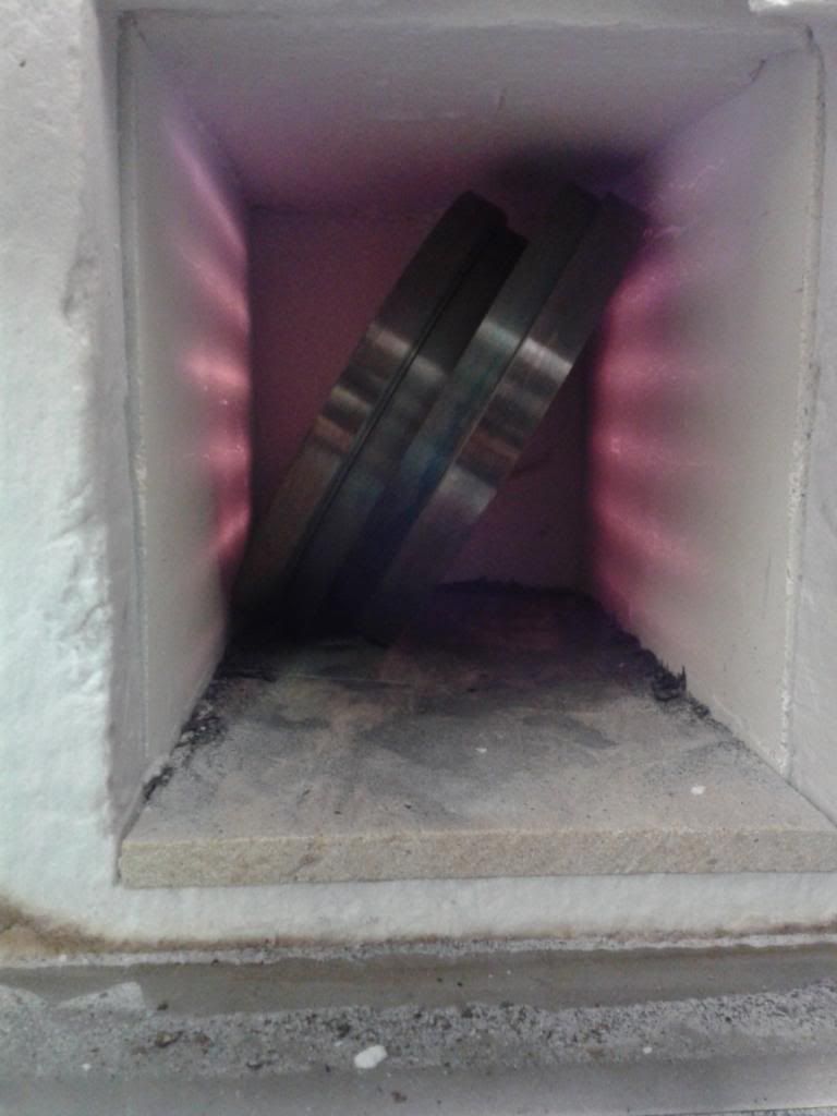 Started finishing off the tyres ready for shrinking on today. First one bored out reay to go, but lathe in use now so won't be able to get on for a few days. Did go and see my friend David again on Friday, borrowed one of his mills to finish off the angles for the buffer beams.... Went to work this afternoon and finished turning the tyres ready for shrinking on...not bad really, £67 and 5 hours machining is a damn sight better than the £400 it cost to get 4 new tyres for Kettle! Some point this week I'll hopefully get them shrunk on. 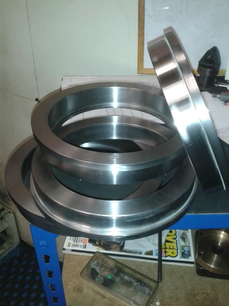 Also made a tool, the tyres are bored out to 6.993", this is 7.000" the same as the wheels are. When this drops in rattles round like a pea in a bucket, then I know they're big enough to drop on...the trick then is making damn sure its square and goes all the way...you only get one shot at this! 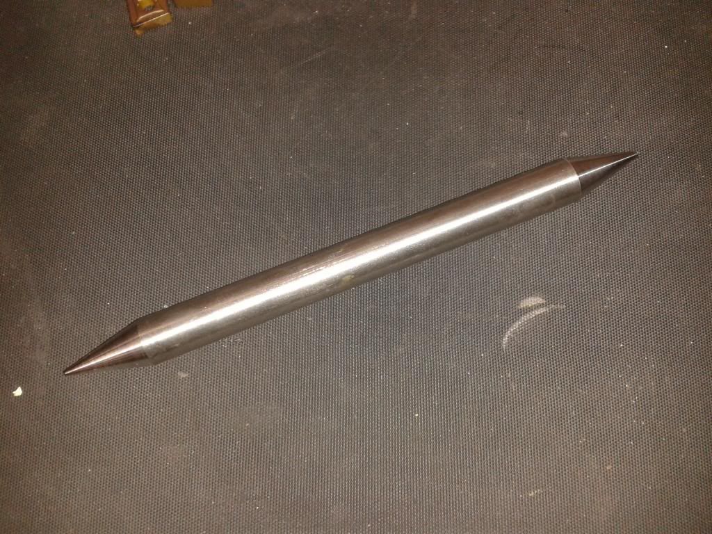 Holly and I also spent a half an hour and riveted on another angle on the buffer beam. Forgot to put up the photo.... 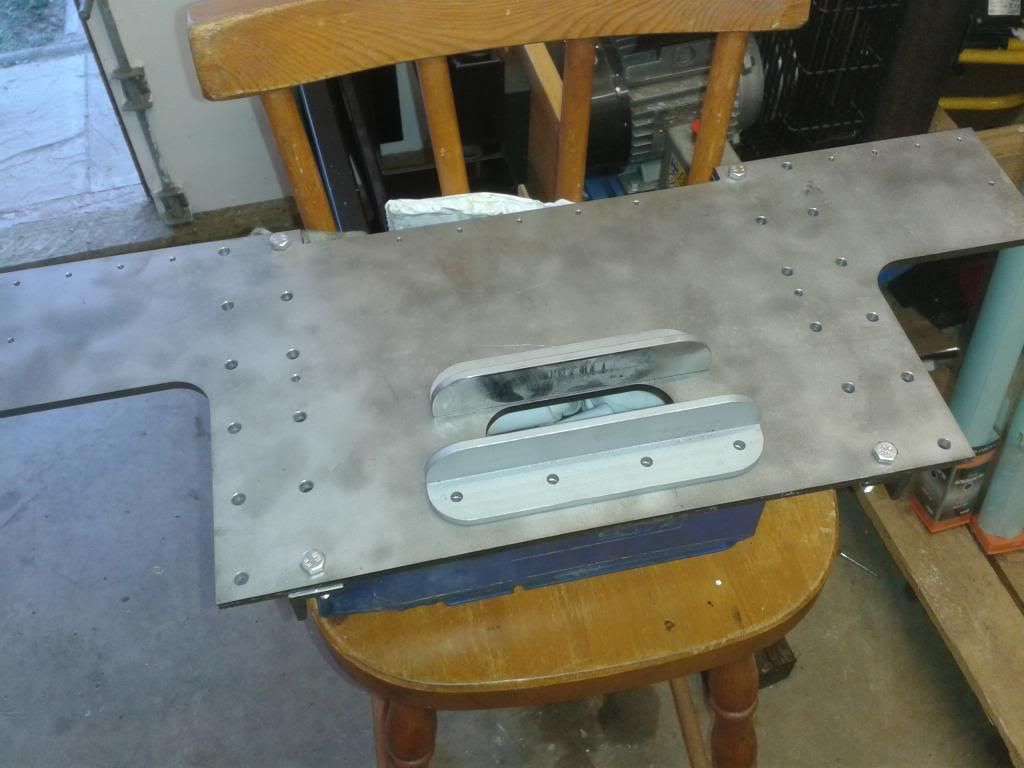 I may have cocked up slightly with these.... I've got a note in my notebook that the front and rear are different, the front one having a long one on the bottom, and the rear the same as the front top. But then when I opened the drawing of the buffer beams I discovered I'd drawn them and had them laser cut the same... hmm... looking at a photo I took years ago seems to corroborate that... so now I'm confused! Will have to wait until I go over to Wales again later in the year and have another look at the real thing. I'll either have to make a new one for the back, or weld up the wrong holes and redrill for the short angle I've made. |
|
|
|
Post by ejparrott on Nov 10, 2013 13:09:58 GMT
Not totally got it wrong after all..the note in my notebook about the rear angles being the same top and bottom was correct, but the only photo I could find was of the inside of the coupler, which is the same front and rear and is wider. I will have to weld up the holes and redrill them for the short angle on the bottom, but that's no problem, I can weld the angle to the beam through the hole at the same time. I'll need to re-do the drawing at some point. I've forgotten to upload the photos of fitting the tyres as well.... Heating to 250 degrees on the bearing heater... 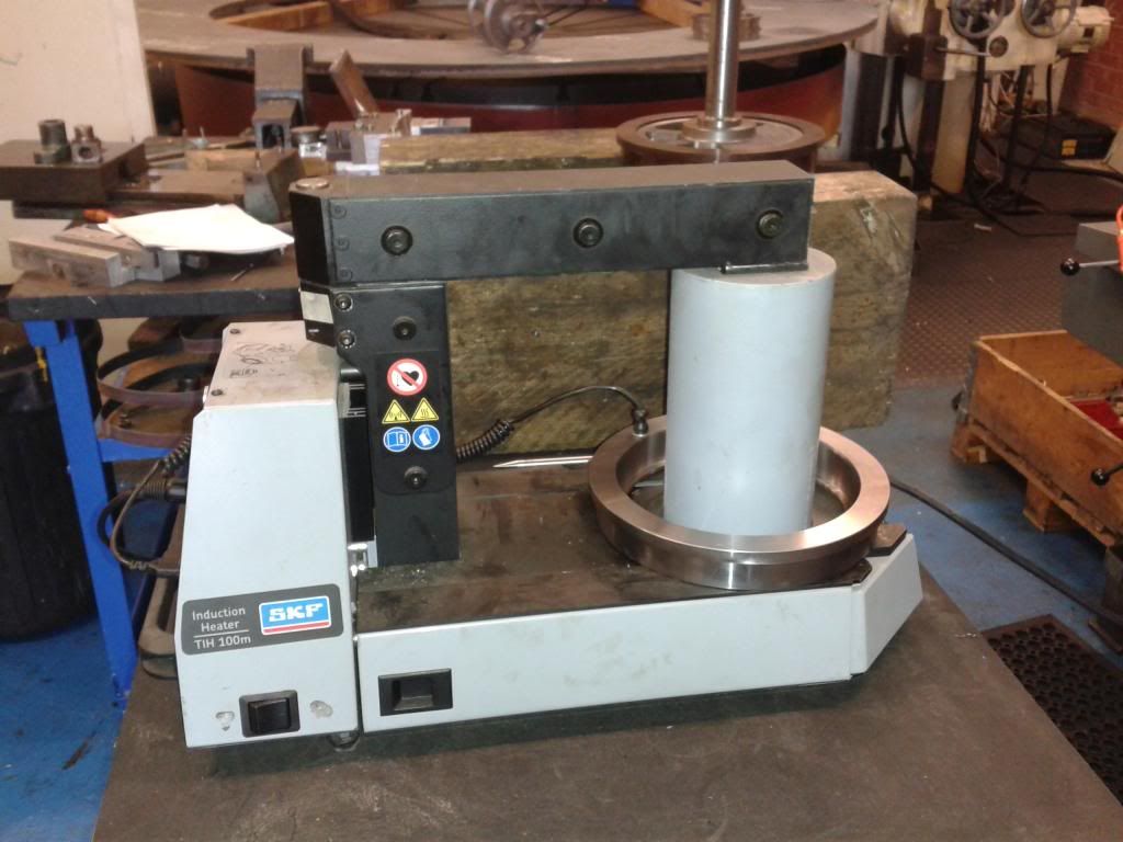 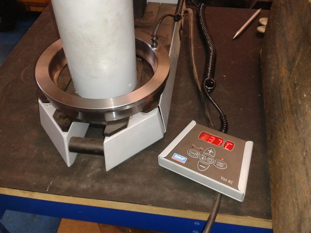 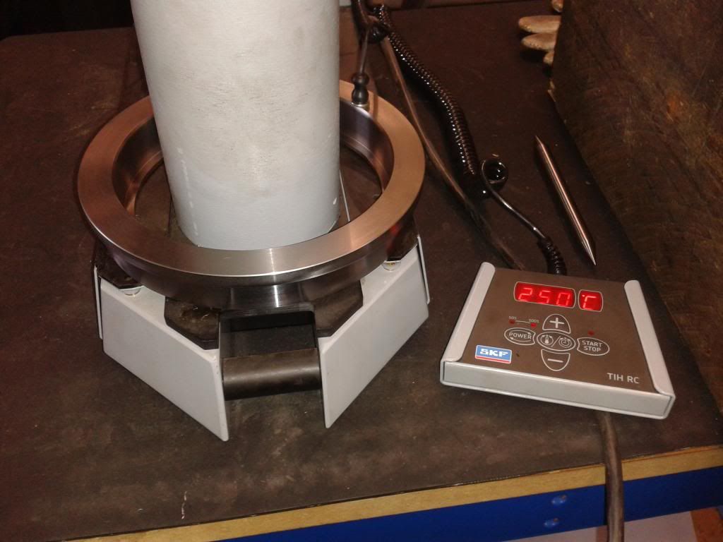 First wheel dropped in, with thermocouple left on to keep an eye on the temperature to let me know when it was 'safe' to turn it over without it falling off again.... 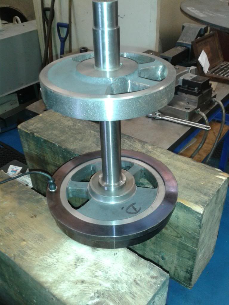 Then repeat... 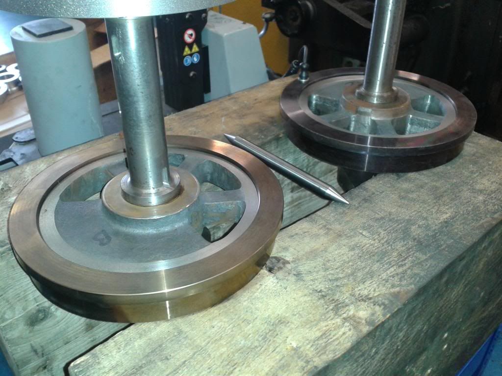 ...and twice more and there you go.... 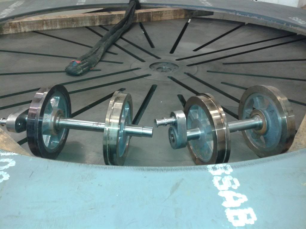 Now I have a slight problem....with the tyres on I can't swing them over the cross slide on my lathe.... censored They'll have to go in the big shaft lathe at work. I need to skim some datums, then shot blast, coat of paint to stop the iron absorbing coolant oil when I finish turn them. Back in the shaft lathe then for finish turning the conical tread, before pressing on the other crank, and a final coat of paint. The rear coupling... Outside... 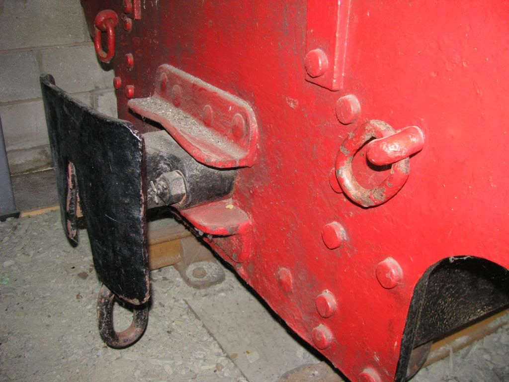 you can see the extra rivet hole at the bottom. Inside... 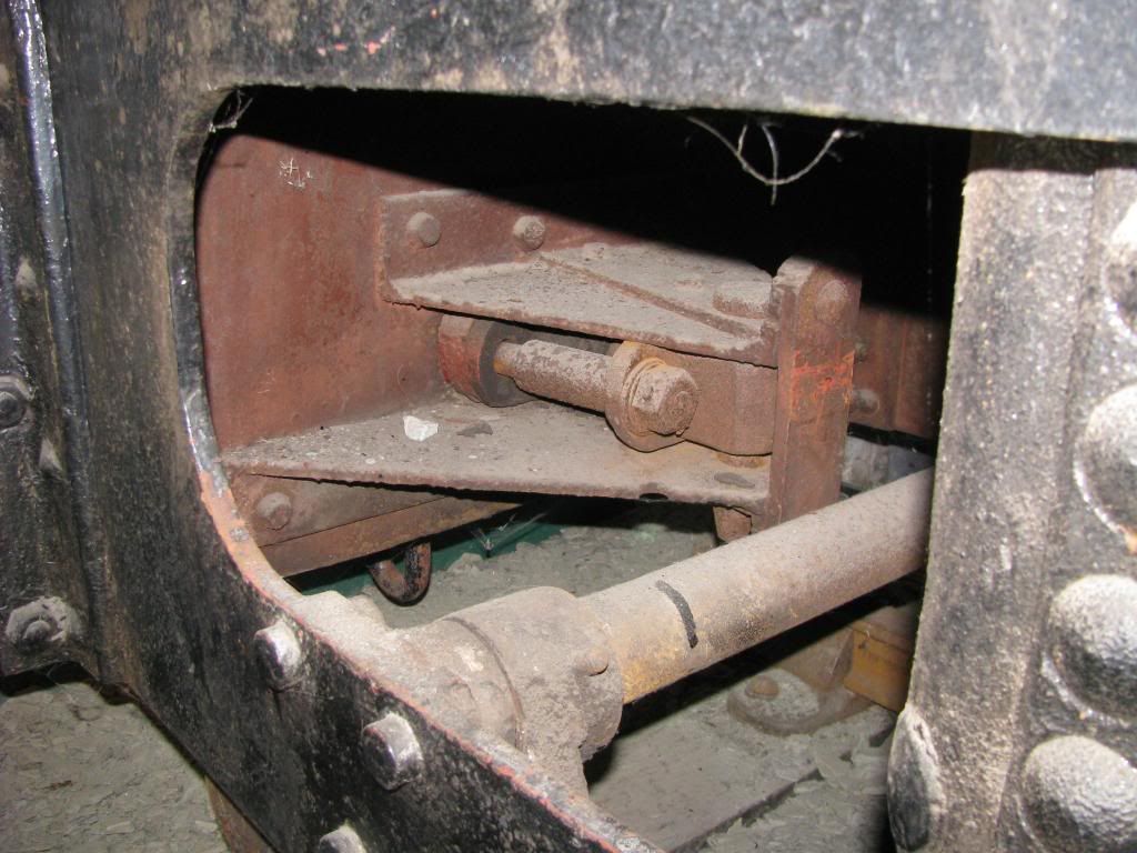 Tonight I've 'insurance' welded the buffer beam angles to the buffer beams. I was just a bit worried about the rivets holding, and I thought I'd play it safe. The joint to the frame will be high tensile fitted bolts in reamed holes, so I'm less concerned about them. After doing that...I could resist.... 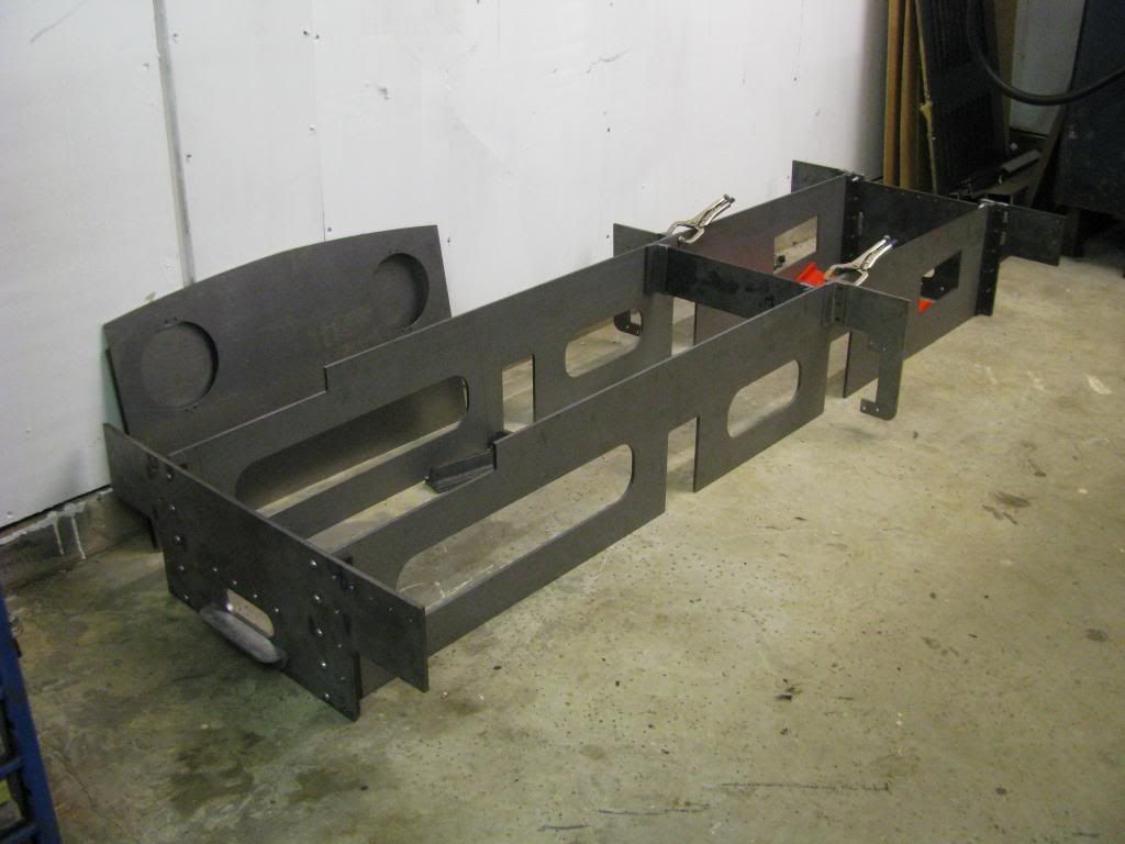 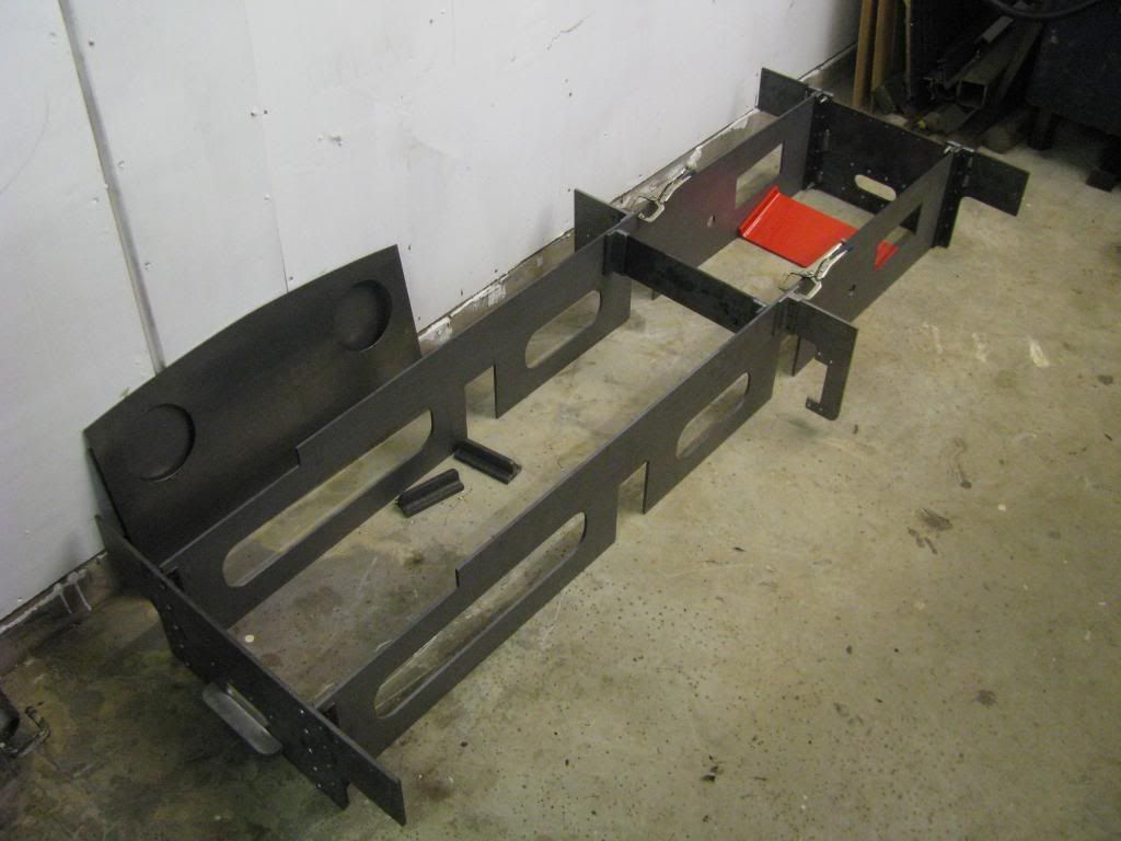 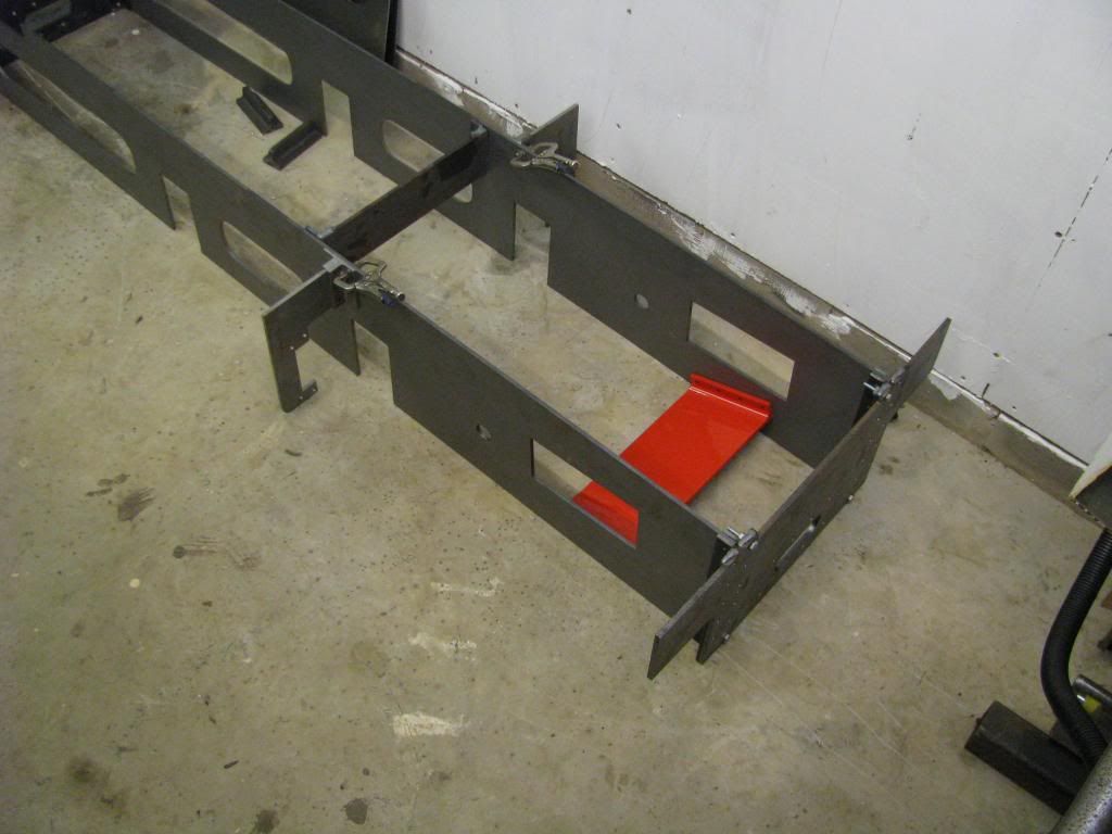 One slightly annoying thing I did find last week....the red stretcher...the one I've finished...isn't fitted any more! I can onlyt assume that at some stage in here life someone needed to get at the cylinder valve chests and needed to remove it...and it was never refitted! The wheels are still at work..otherwise I'd have put them in too! Did another half hour tonight, started riveting the cab plate-work together. Its not easy trying to handle large sheets of steel on your own, whilst trying to hammer over 3/32" rivets! There's worse to come too....so far I've just put the angles to one side of the plate, never mind joining the two together! Just the 2 at the moment, one of each side of the front plate (generally known as the spectacle plate) and the angle down each side.... 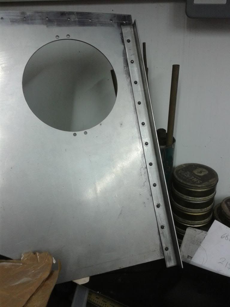 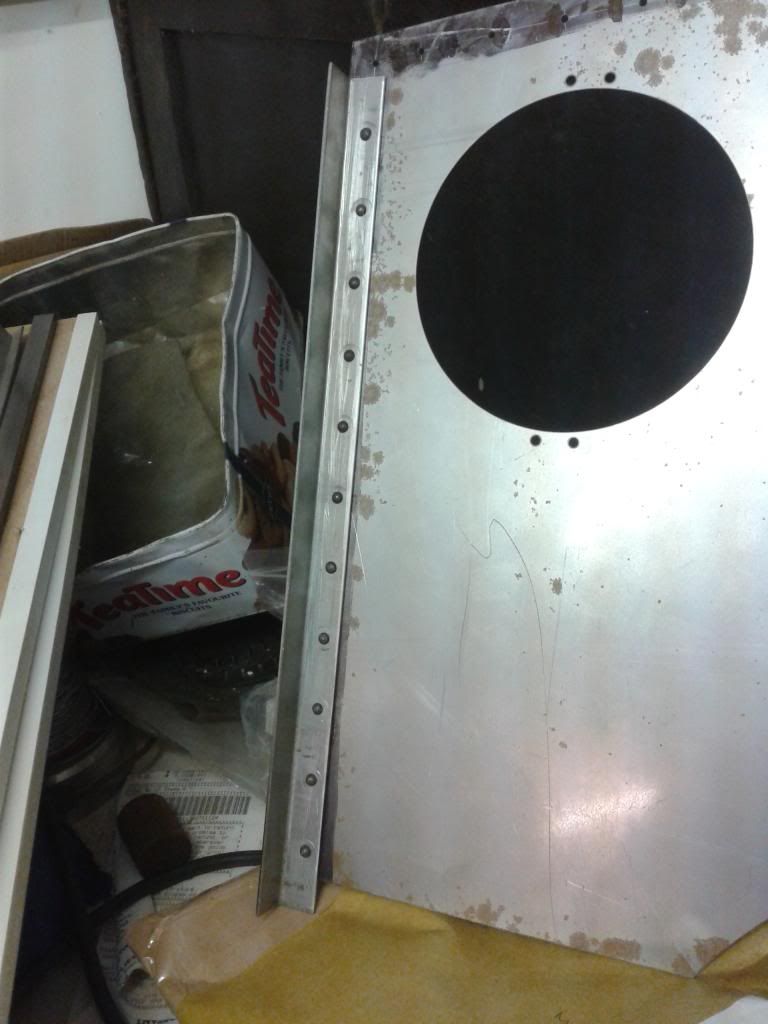 There's going to be a fair bit more to do yet, I'll make sure I save some for you. Next job is to finish drilling holes in the curved section which goes across the top, then rivet that on. Take it up to my friendly sheet metal workers and get some angle folded then to match it, ready for riveting down the side. That will then be countersunk riveted to the side sheets, as on the real one the side sheet is bent over, but I decided that for the model separate pieces would be easier. I've just skimmed some datums on the wheelsets....made them look small again.... 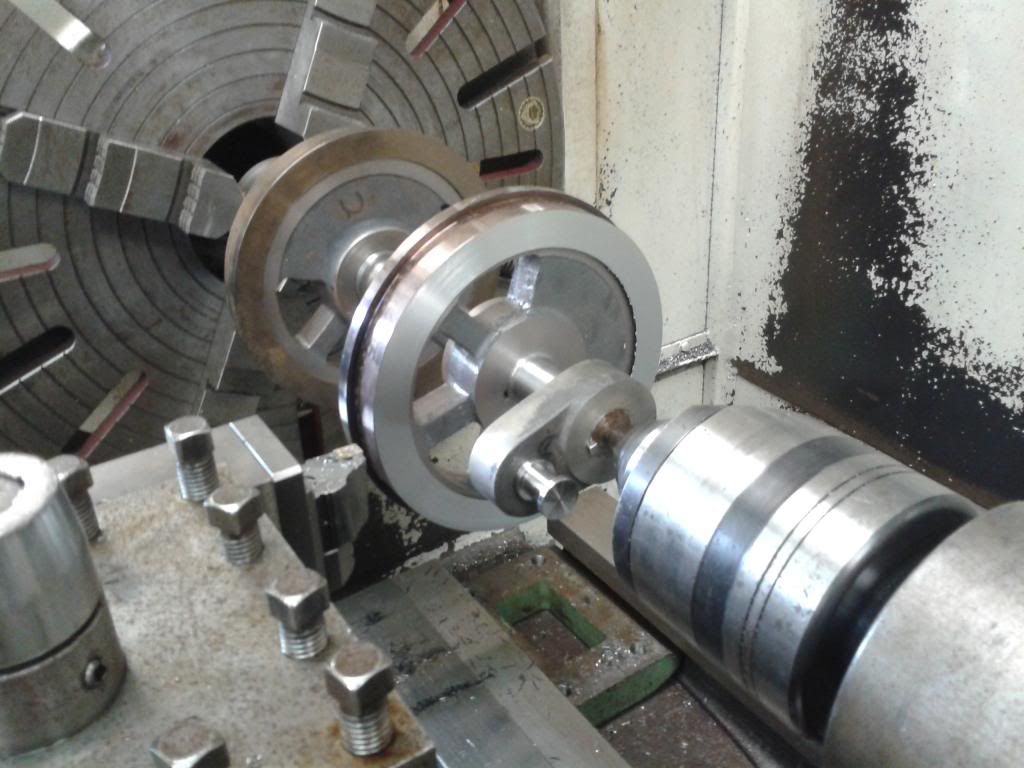 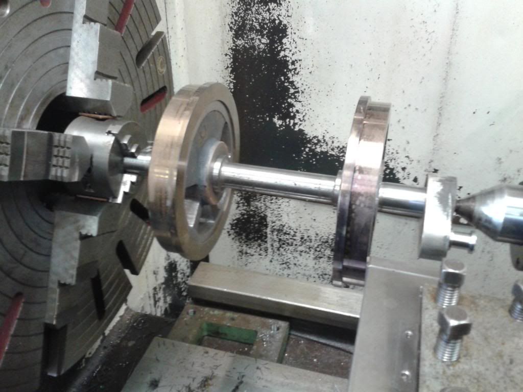 I'll take them home now for the weekend, mask off all the bearing surfaces, then hopefully shot-blast on Monday, prime Monday night, and get painted before Friday, leaving me to finish turn the tyres next Friday afternoon...i hope! |
|
|
|
Post by ejparrott on Nov 10, 2013 13:12:05 GMT
Holly masked up the wheelsets on Sunday, they were shotblast this morning, and a coat of primer is drying in the workshop overnight... all being well, I'll get the red paint on tomorrow and Thursday.... I really want a go at that riveting malarkey! Can we get some pictures of progress however minor, please? You'll get a chance, I've got about a thousand of the little buggers to put in a 5" gauge model of a GWR Toad brake van..... Coat of primer Tuesday night.... 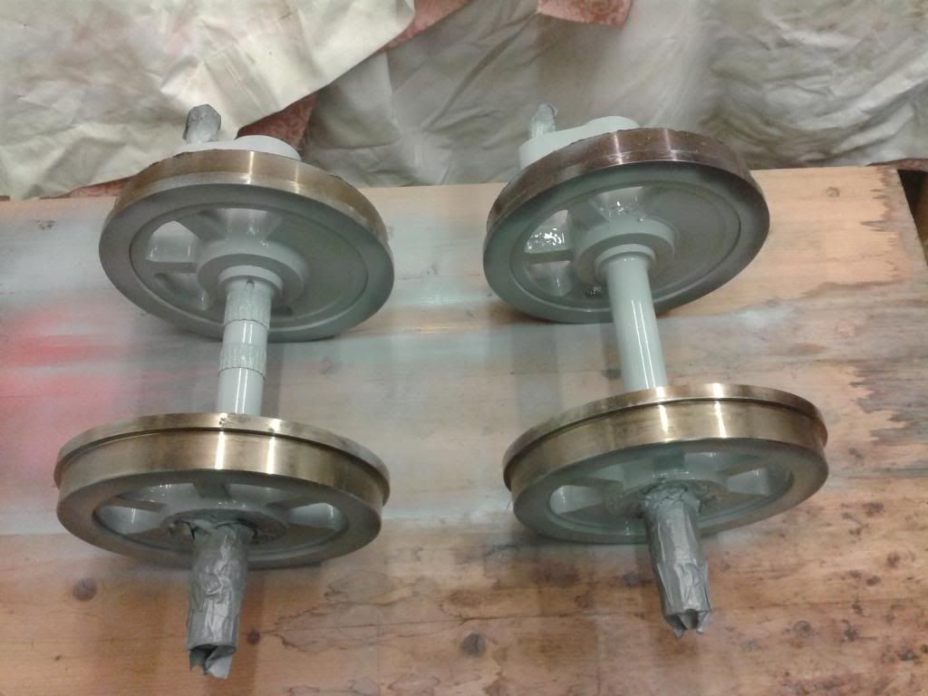 Last night the first of the red top coats went on... 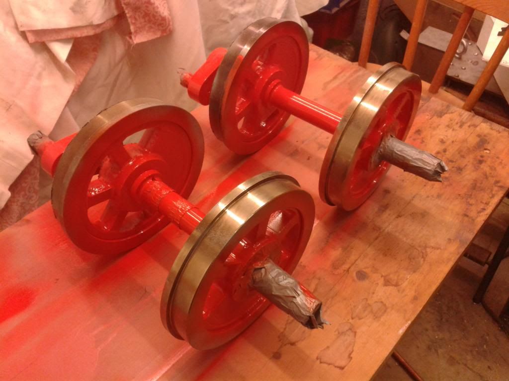 When it warms up a bit (its only 5.9degreesC at the minute!) I'll spend today finishing off the top coat. Tomorrow afternoon then I'll hopefully get them back in the lathe at work for finish turning of the tyres. Then I need to finish off the other two cranks, paint them, and press them on the axle. Just might be time for another photo of them between the frames then.... Had permission from my boss to go in to work over the christmas shut down and get on with the engine....Frames could well be bolted together before 2014! I hadn't realised I hadn't updated this... I got the wheels back in the lathe, and have finish turned the tyres now.... 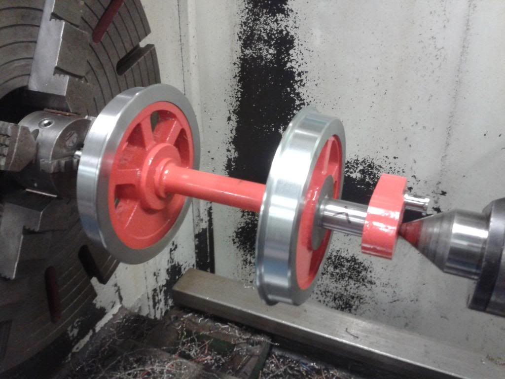  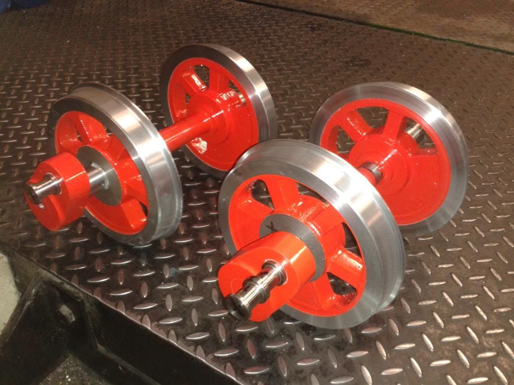 www.youtube.com/watch?v=TUhcLUkzLvw#ws www.youtube.com/watch?v=TUhcLUkzLvw#wsLast night I borrowed a friends CNC lathe and made about 60 fitted bolts for the assembly of the frames.... 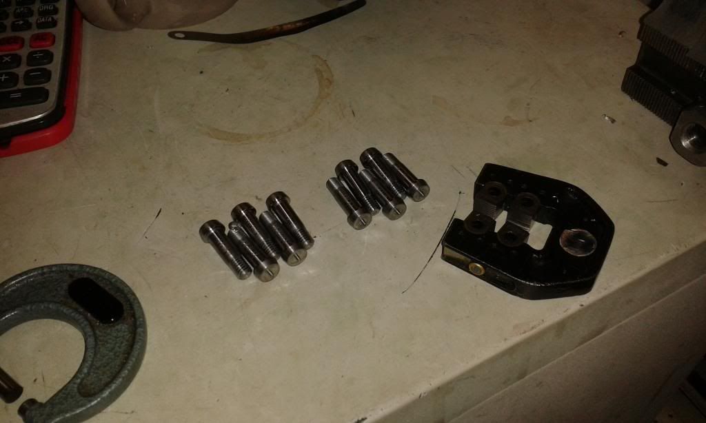 These will be individually fitted to the holes I drill when the frames are assembled, hopefully during Christmas week. The idea is that the plain portion behind the thread is the exact same size, or a fraction bigger, than the hole in to which it fits. They are then driven in, and serve to line everything up, take the shear loads placed through the chassis whilest working, and unlike a dowel, hold the bits together. It'll be a long job fitting them, but I'll know my chassis won't be moving any time soon! These are made from EN24T steel, good and tough. www.youtube.com/watch?v=b6N5jZ9-uvs#ws |
|
|
|
Post by ejparrott on Nov 10, 2013 13:14:08 GMT
Holly masked up the wheelsets on Sunday, they were shotblast this morning, and a coat of primer is drying in the workshop overnight... all being well, I'll get the red paint on tomorrow and Thursday.... I really want a go at that riveting malarkey! Can we get some pictures of progress however minor, please? You'll get a chance, I've got about a thousand of the little buggers to put in a 5" gauge model of a GWR Toad brake van..... Coat of primer Tuesday night.... Last night the first of the red top coats went on... When it warms up a bit (its only 5.9degreesC at the minute!) I'll spend today finishing off the top coat. Tomorrow afternoon then I'll hopefully get them back in the lathe at work for finish turning of the tyres. Then I need to finish off the other two cranks, paint them, and press them on the axle. Just might be time for another photo of them between the frames then.... Had permission from my boss to go in to work over the christmas shut down and get on with the engine....Frames could well be bolted together before 2014! I hadn't realised I hadn't updated this... I got the wheels back in the lathe, and have finish turned the tyres now.... www.youtube.com/watch?v=TUhcLUkzLvw#wsLast night I borrowed a friends CNC lathe and made about 60 fitted bolts for the assembly of the frames.... These will be individually fitted to the holes I drill when the frames are assembled, hopefully during Christmas week. The idea is that the plain portion behind the thread is the exact same size, or a fraction bigger, than the hole in to which it fits. They are then driven in, and serve to line everything up, take the shear loads placed through the chassis whilest working, and unlike a dowel, hold the bits together. It'll be a long job fitting them, but I'll know my chassis won't be moving any time soon! These are made from EN24T steel, good and tough. www.youtube.com/watch?v=b6N5jZ9-uvs#ws |
|
|
|
Post by ejparrott on Nov 10, 2013 13:15:50 GMT
And that brings it up to date, certainly everything I've documented. Did spend an hour at work yesterday printing out large drawings of the frames and locating all the laser spots. Did find two errors on them, one from the drawing stage when I put three bolts in for a stretcher instead of four for some reason, and also the guides for the springs are too far apart...not sure why yet.
I'll keep the thread up to date now, and it'll make more sense in future.
|
|
|
|
Post by Ruston92 on Nov 10, 2013 15:59:45 GMT
Beautiful work there!
|
|
|
|
Post by ejparrott on Nov 10, 2013 16:09:02 GMT
Thanks...hopefully it'll only get better!
|
|


