|
|
Post by ejparrott on Jul 24, 2014 7:55:24 GMT
One of the worst things about side tank models is the balance pipe from one to the other. Frequently inaccessible, frequently taken across the cab floor un-protoypically with massive ME pipe fittings, and a constant source of teeth nashing when tank removal is required. I take no credit for the idea, but I cannot for the life of me remember where I first came across it, but it is possible to do with a very simple push-fit fitting that just uses an O ring for a seal. Removing the tank is literally case of undoing the fixing screws and pull....refitting is the reverse. 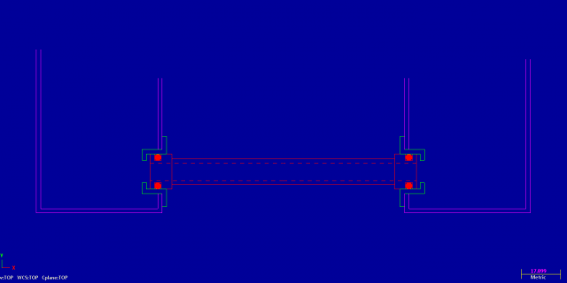 Don't know if this might show better.... 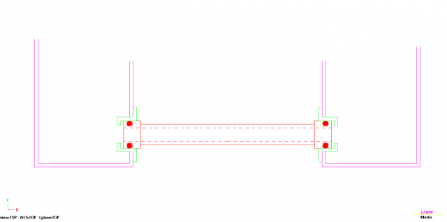 blue I find great for doing the CAD against, not so good for screen shots. The balance pipe just has two ferrules soldered on the end with 2 o ring grooves, then the tank has the two bushes. The important thing is not to end up in a situation where the pipe could work its way right through in to one tank. On this example the step on the inside of the bush would prevent that, and the tube should be about 1/16" shorter than the gap so it can expand if it want's to, and so that it doesn't place any load on the tank sides. Alternativly, the bush in the tank side can be a plain tophat through bush, and to stop the pipe sliding through it should have a head turned behind the O ring. Again, measured up so that it's shy and deosn't load the tank. All dimensions to be taken from the engine and designed to suit, no point me dimensioning anything. The balance pipe should be as large as possible, as low as possible, and ideally complete with a drain tap. |
|
bhk
Part of the e-furniture

Posts: 458 
|
Post by bhk on Jul 24, 2014 8:01:20 GMT
One of the worst things about side tank models is the balance pipe from one to the other. Frequently inaccessible, frequently taken across the cab floor un-protoypically with massive ME pipe fittings, and a constant source of teeth nashing when tank removal is required. I take no credit for the idea, but I cannot for the life of me remember where I first came across it, but it is possible to do with a very simple push-fit fitting that just uses an O ring for a seal. Removing the tank is literally case of undoing the fixing screws and pull....refitting is the reverse. Don't know if this might show better.... blue I find great for doing the CAD against, not so good for screen shots. The balance pipe just has two ferrules soldered on the end with 2 o ring grooves, then the tank has the two bushes. The important thing is not to end up in a situation where the pipe could work its way right through in to one tank. On this example the step on the inside of the bush would prevent that, and the tube should be about 1/16" shorter than the gap so it can expand if it want's to, and so that it doesn't place any load on the tank sides. Alternativly, the bush in the tank side can be a plain tophat through bush, and to stop the pipe sliding through it should have a head turned behind the O ring. Again, measured up so that it's shy and deosn't load the tank. All dimensions to be taken from the engine and designed to suit, no point me dimensioning anything. The balance pipe should be as large as possible, as low as possible, and ideally complete with a drain tap. Nice one Ed, Just for those who still are unsure of this idea, Wartsils use this for there fuel oil leakage pipes on there marine Diesel engines. |
|
|
|
Post by Doug on Jul 24, 2014 8:07:31 GMT
fantastic thanks Ed so much easier to understand once you can see the concept :-)
|
|


