|
|
Post by Deleted on Dec 17, 2014 14:23:10 GMT
Fred, the Bill Hall simulator for Stephensons is fairly simple to use. You can download it from Don Ashton's website: www.donashton.co.uk/html/downloads.htmlThe Allan Wallace one is good but requires some dimensions that are not easy to determine. John |
|
|
|
Post by fredvv44 on Dec 18, 2014 23:55:22 GMT
Thanks John. I'll do my home work.
Fred
|
|
|
|
Post by fredvv44 on Dec 21, 2014 0:11:32 GMT
Thanks John. I'll do my home work. Fred I've been working with the Hall simulator program. Here are my results. I don't know how close I got so I hope one of you will be able to analyze what I've done. I didn't know what to use for data entry for % of advance or what to put for the lifting arm angle in the results page. The results are here: s1153.photobucket.com/user/fredvv44/media/ScreenShot2014-12-20at60327PM.png.html?sort=3&o=0Right click the image and click "view image" then click the (+) sign. I think you can read it then. Fred V |
|
|
|
Post by Deleted on Dec 21, 2014 1:32:49 GMT
Fred,
I can't check your figures without a set of drawings but some of your data entries look suspect. (I've only got drawings for Don's 5" version)
The steam lap looks wrong at 0.063" as does the exhaust lap at 0.1875". I would expect the steam lap to be 0.125" to 0.1875" and the exhaust lap, if any, to be quite small. Is the expansion link suspended from the middle, top, or bottom?
The angle of advance for the eccentrics is difficult to guess if not shown on the drawings but I usually set it to give 0.010" lead at 50% cut off.
Any chance of you posting a drawing showing the valve dimensions and the expansion link?
John
|
|
|
|
Post by fredvv44 on Dec 21, 2014 13:37:36 GMT
Fred, I can't check your figures without a set of drawings but some of your data entries look suspect. (I've only got drawings for Don's 5" version) The steam lap looks wrong at 0.063" as does the exhaust lap at 0.1875". I would expect the steam lap to be 0.125" to 0.1875" and the exhaust lap, if any, to be quite small. Is the expansion link suspended from the middle, top, or bottom? The angle of advance for the eccentrics is difficult to guess if not shown on the drawings but I usually set it to give 0.010" lead at 50% cut off. Any chance of you posting a drawing showing the valve dimensions and the expansion link? John Thanks John, A drawing is here: s1153.photobucket.com/user/fredvv44/media/ScreenShot2014-12-21at72912AM.png.html?sort=3&o=0Lap should be .125" and exh. lap zero. It looks like this program is trying to tell me what the advance angle will be to give even cutoff oat 50% but I need to study it more as this is my first look at it. I'm very familiar with the the American program but this one is quite different. Fred |
|
|
|
Post by Deleted on Dec 21, 2014 15:12:54 GMT
Hi Fred, OK, these are the dimensions you should have in the simulator: 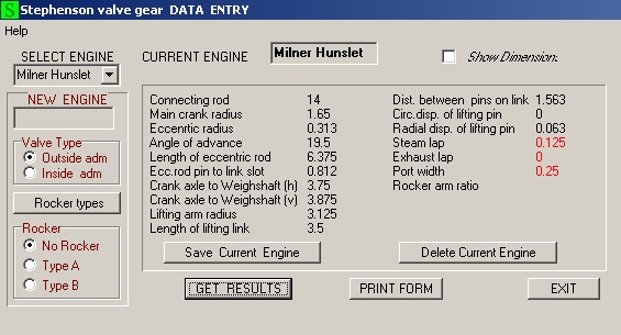 And the results:  Not very good at all! If you increase the offset of the lifting pin from 0.063 to 0.443 it pretty much evens the cut offs out at 50% but it's a big offset:  It may help to try altering the length of the lifting arms on the weighshaft as well. Incidently, are the dimensions for the position of the weighshaft taken from the axis of the motion as they should be (as the cylinders are inclined)? John |
|
|
|
Post by fredvv44 on Dec 21, 2014 21:43:18 GMT
That looks much better indeed. I was not sure just what they were asking for on some of those dims. so i was guessing. For the location of the weightshaft I took the horizontal and vertical dim. from the axle center. What should it be? Is there a problem with moving the lifting pin on the link back by .443"? The weightshaft could be moved back and lengthen the lifting arm but I don't see how that would help. A longer lifting link would help but that would mean moving the weightshaft above the frame. Frame drawing: s1153.photobucket.com/user/fredvv44/media/ScreenShot2014-12-21at23428PM.png.html?sort=3&o=0How are you able to add attachments? I get a message that something is overloaded and exceeded it's limit. Thanks for you time to help with this. Fred |
|
jma1009
Elder Statesman

Posts: 5,901
|
Post by jma1009 on Dec 21, 2014 23:08:22 GMT
hi john,
thank you very much for working out the details on the simulator - although for fred's benefit they are also of great interest to me due to the views i expressed on here on 17th december - which your simulation confirms.
hi fred,
providing the suspension offset on the expansion link for the bottom of the lifting link cures one major flaw of the milner design. however the very short lap is still present - just 50% of port width. i usually start with 75% and others favour more.
i recall that the rather restrictive and odd circular steam chests will just accomodate a longer lap and hence longer valve travel, and so (1) the length of the expansion link slot can be lengthened easily without any 'fouls'. or you could (2) reduce the steam port width to 3/16" which will give 66% lap of port width which is a bit of an improvement. i would favour option (1)
cheers,
julian
|
|
|
|
Post by Deleted on Dec 22, 2014 0:41:11 GMT
Hi Julian, I like playing with valve gears as you've probably noticed and if we can make some improvements along the way then so much the better  I agree that the lap could be increased ( I would go for 0.1875" as you suggest) but that will mean a radical redesign of the valve gear to give the increased valve travel necessary. I don't know if Fred wants to go down that route? Maybe the valve gear has already been made? Fred - it's important that all the dimensions for the simulators such as the position of the weighshaft are taken from the centreline of the motion (the line through the cylinders and the driving axle, your dotted yellow line on your CAD drawing) otherwise the results will be inaccurate. Can you email me a copy of your CAD file for the frames? I should be able to open it in my Autocad 2000 and get the dimensions. Altering the length of the lifting arm on the weighshaft (or moving the weighshaft itself) moves the suspension point of the top of the lifting link relative to the suspension pin on the expansion link and this can have profound effects on the valve events. John |
|
|
|
Post by fredvv44 on Dec 22, 2014 14:28:21 GMT
Thanks guys,
I've not made parts yet so I'm open to doing anything. I'm willing to be a test bed for this if you like. It looks like there is enough thickness in the steamchest casting to bore the ID to make more room for valve travel.
John, I've emailed you the cad drawing. you will see that I've been playing with the design some already. I'll remeasure for the weightshaft working off the cyl. line and plug that into the simulator. I changed my data input to match yours but I come up with slightly different numbers in the results window.
Fred
|
|
|
|
Post by Deleted on Dec 22, 2014 18:19:03 GMT
Thanks for the drawing Fred. I've recalculated the valve gear from scratch using Don's spreadsheet and got quite good results. I've left the lap at 0.125" for the time being. I used the Alan Wallace simulator for the results as I prefer the diagrams that this gives. It's very easy to see how matched the events are at each end of the cylinder. 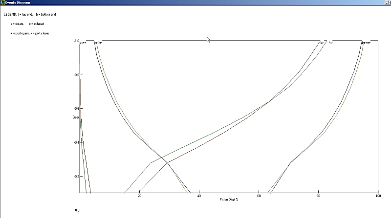 You can see everything is pretty close at both ends although things are not perfect at the top and bottom of the cut off range but still within 2-3%. Things could be improved more with a bit more tweaking perhaps but you probably wouldn't notice the difference in practice. Reverse gear is identical to forward gear. Some of the dimensions given by the spreadsheet are slightly different: Eccentric throw is 0.355" Eccentric rod length is 6.384" Offset of the suspension pin on the expansion link is 0.41" Length of lifting arm on weighshaft is 2.61" Weighshaft position as original The ports don't need to open anything like fully to give 80% cut off in full gear. Fully opening the ports gives you something like 90% cut off which you shouldn't need. I've not looked at increasing the lap to 0.1875" but can do if you like. I'm wondering though if the increased throw on the eccentrics needed would cause problems with the eccentric hitting the front of the firebox as they are probably quite close at the moment? Hope this all helps anyway. John |
|
|
|
Post by fredvv44 on Dec 22, 2014 18:35:49 GMT
John, I looked at the steam chest and if the inside is opened up about 1/8" a valve with 3/16" lap would have about .850" of travel. That give a fully open port but, as you say, that isn't needed. If you wouldn't mind running the numbers with the increased lap it would be nice to see if it would be an additional improvement.
Fred
|
|
jma1009
Elder Statesman
Posts: 5,901
|
Post by jma1009 on Dec 22, 2014 22:07:52 GMT
hi john,
there is enough room behind the eccentric sheaves and straps for a larger throw, or you can extend the length of the slot in the expansion link.
of course fred really ought to ditch those awful circular steam chests and fit ones that follow fullsize, and fit loco links as per fullsize. with loco links the correct suspension offset wont be so great.
cheers,
julian
|
|
|
|
Post by fredvv44 on Dec 23, 2014 13:54:16 GMT
hi john, there is enough room behind the eccentric sheaves and straps for a larger throw, or you can extend the length of the slot in the expansion link. of course fred really ought to ditch those awful circular steam chests and fit ones that follow fullsize, and fit loco links as per fullsize. with loco links the correct suspension offset wont be so great. cheers, julian That would be nice but finding parts to do that would be quite a task. I would also need the port block and probably larger eccentrics to get the needed throw. I think (hope) improving the valve events and adding a superheater will make it a nice running engine. Fred |
|
|
|
Post by fredvv44 on Dec 23, 2014 14:01:06 GMT
|
|
|
|
Post by fredvv44 on Feb 4, 2015 19:22:58 GMT
delete post
|
|
|
|
Post by fredvv44 on Jun 12, 2015 12:40:08 GMT
I've made a lot of progress. See pix at s1153.photobucket.com/user/fredvv44/library/?sort=3&page=1 I am ready to make the pistons/crossheads. The drawing shows to ream the crosshead and pin the pistonrod in along with a setscrew. That doesn't look like a great way to do it. The piston is screwed onto the rod. What did you guys do? thanks, Fred V Read more: modeleng.proboards.com/thread/9846/hunslet-milner-drawings#ixzz3cqpO3Nj3 |
|
|
|
Post by fredvv44 on Aug 1, 2015 23:00:58 GMT
I now have it running on air. www.youtube.com/watch?v=ae3vYIoUQS4&feature=youtu.beThe expansion links kick a lot but I think when I get the Johnson bar mounted the motion will settle down. Also the lifting arms are not parallel so that adds some unwanted motion. I'll post another video when I get it running batter. The valve design was made as discussed in the above posts with the suspension point moved back and the lifting arms shortened. Even with it all as out of wack as it is it runs quite smooth. Any opinions or suggestions are welcome. Fred V |
|


 I agree that the lap could be increased ( I would go for 0.1875" as you suggest) but that will mean a radical redesign of the valve gear to give the increased valve travel necessary. I don't know if Fred wants to go down that route? Maybe the valve gear has already been made?