

Post by springcrocus on Aug 17, 2014 12:10:55 GMT
Brake blocks from castings - start to finish
I've read numerous posts regarding the maching of brake blocks and it appears that many people favour machining these from scratch using an old car brake disc or similar. However, some of us (I include myself here) bought, or were supplied with, the castings as specified on the drawings. However, the accuracy and finish of the castings often leaves much to be desired and the problem of machining them can also present some difficulties, particularly if there is only very basic tools and machinery available to complete the task.
Some say that brake blocks were rough-cast in full-scale and you only need to mill the slot, drill the brake pin hole and machine the area that touches the wheel. I, personally, prefer not to have rough castings with minimal machining and would rather finish-machine all over. So, for anyone who's interested, here's how I went about the task.
These are the brake blocks, as supplied, for the BR1 tender (Norman Spinks 5" gauge Britannia drawings with Les Warnett's BR1G tender).

First, I cut the blocks into individual pieces and marked out where I wanted the brake pin hole to be in each blocK. The hole size in my blocks is specified as 3/16" so I drilled and tapped these holes at 2BA, this being the largest thread that is SMALLER than the finished hole (you'll see why in a minute). The next job was to face front and back of the blocks for a flat and level finish. Facing off in the lathe seemed the easiest way so a means of holding them was needed. Because I have soft jaws for my chuck, I made a carrier plate onto which I could bolt the brake blocks and then load to the soft jaws.
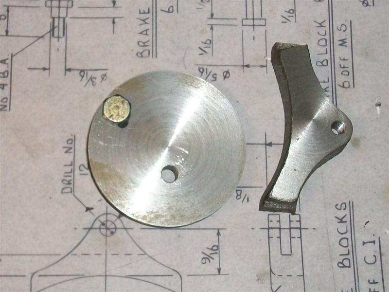
I happened to have a mild steel blank of 1.7/8" dia x 1/4" thick but any old bit of steel would do. After facing off and turning a dia for trueness, then reversing and facing the back, I have drilled a 2BA clearance hole in it to mount the brake block, bolted from the back, and also added an anti-rotation pin to hold it firm against the cut.

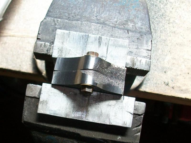
Once both sides were faced ( a bit undersize in my case, but all the same thickness) the next thing was to get the length of the block machined which I did in my small milling machine. Each brake block was placed in the vice using the bottom slot of the vice to centre it and then aligning the block by eye. There will bound to be a more accurate way but I don't think it matters that much.

Because the width of my vice (1.618") is less than finish size of the brake blocks (1.750"), I was able to mill one side to size (0.066" from side of vice) and then do the other side to finish at the required size.

Next I had to clean up the outer edges of the brake blocks so it was time to open the tapped holes up to their finished size. One of mine was a bit adrift so I opted to mount the blocks in the vice, holding on the milled flats, and use a 3/16" slot drill to align the holes more accurately. Some of the blocks have a slight witness of the thread but it's not important - there's a pin through there on assembly.

Most castings have a draft angle and I bolted mine together in pairs with the smaller faces together and then started to clean up the profiles using a carbide burr in my dremmell (it's not made by Dremmel, but then, most hoovers are not made by Hoover)

and finishing off with a small drum sander for the internal radii and my belt linisher for the external radii.


That only left the wheel-form part of the job to do and the slot.
Using the same soft jaws as earlier, I drilled and tapped a 2BA thread in the top of each jaw

and loosely bolted three of the blocks to the jaws. Then I gently clamped the jaws onto a finished wheel to align them and finally pulled the bolts up tight. I used cap screws because they are normally high-tensile and you can get them good and tight.
 ]
]
Then I wound the jaws down onto an adjustable ring (normal soft-jaw accessory) to leave about 30 thou to come out.

I would have liked to have included some sort of anti-rotation pin to the setup but decided that all would be okay with small cuts and a gentle touch.

I took 5 thou depth of cut (10 thou dia) and used the wheel as a gauge. I managed to go a bit too far on the first set so I undid the chuck, adjusted the setting ring to a bit smaller, and had another go.
Finally, time to put the slot in. I don't have much in the way of slitting saws so opted to mill them out using a 1/8" slot drill (of which I have loads).

However, they are not deep enough so I freehand ground a bit of the shank down and milled the slots in two hits, saving my home-made long-series slot drill to finish the depth. And here is the finished article - well six actually.

Next job will be to see if I can adapt what I have done for the driving wheels but at over 6" I might be stretching things a bit.
Steve
I've read numerous posts regarding the maching of brake blocks and it appears that many people favour machining these from scratch using an old car brake disc or similar. However, some of us (I include myself here) bought, or were supplied with, the castings as specified on the drawings. However, the accuracy and finish of the castings often leaves much to be desired and the problem of machining them can also present some difficulties, particularly if there is only very basic tools and machinery available to complete the task.
Some say that brake blocks were rough-cast in full-scale and you only need to mill the slot, drill the brake pin hole and machine the area that touches the wheel. I, personally, prefer not to have rough castings with minimal machining and would rather finish-machine all over. So, for anyone who's interested, here's how I went about the task.
These are the brake blocks, as supplied, for the BR1 tender (Norman Spinks 5" gauge Britannia drawings with Les Warnett's BR1G tender).
First, I cut the blocks into individual pieces and marked out where I wanted the brake pin hole to be in each blocK. The hole size in my blocks is specified as 3/16" so I drilled and tapped these holes at 2BA, this being the largest thread that is SMALLER than the finished hole (you'll see why in a minute). The next job was to face front and back of the blocks for a flat and level finish. Facing off in the lathe seemed the easiest way so a means of holding them was needed. Because I have soft jaws for my chuck, I made a carrier plate onto which I could bolt the brake blocks and then load to the soft jaws.
I happened to have a mild steel blank of 1.7/8" dia x 1/4" thick but any old bit of steel would do. After facing off and turning a dia for trueness, then reversing and facing the back, I have drilled a 2BA clearance hole in it to mount the brake block, bolted from the back, and also added an anti-rotation pin to hold it firm against the cut.
Once both sides were faced ( a bit undersize in my case, but all the same thickness) the next thing was to get the length of the block machined which I did in my small milling machine. Each brake block was placed in the vice using the bottom slot of the vice to centre it and then aligning the block by eye. There will bound to be a more accurate way but I don't think it matters that much.
Because the width of my vice (1.618") is less than finish size of the brake blocks (1.750"), I was able to mill one side to size (0.066" from side of vice) and then do the other side to finish at the required size.
Next I had to clean up the outer edges of the brake blocks so it was time to open the tapped holes up to their finished size. One of mine was a bit adrift so I opted to mount the blocks in the vice, holding on the milled flats, and use a 3/16" slot drill to align the holes more accurately. Some of the blocks have a slight witness of the thread but it's not important - there's a pin through there on assembly.
Most castings have a draft angle and I bolted mine together in pairs with the smaller faces together and then started to clean up the profiles using a carbide burr in my dremmell (it's not made by Dremmel, but then, most hoovers are not made by Hoover)
and finishing off with a small drum sander for the internal radii and my belt linisher for the external radii.
That only left the wheel-form part of the job to do and the slot.
Using the same soft jaws as earlier, I drilled and tapped a 2BA thread in the top of each jaw
and loosely bolted three of the blocks to the jaws. Then I gently clamped the jaws onto a finished wheel to align them and finally pulled the bolts up tight. I used cap screws because they are normally high-tensile and you can get them good and tight.
]Then I wound the jaws down onto an adjustable ring (normal soft-jaw accessory) to leave about 30 thou to come out.
I would have liked to have included some sort of anti-rotation pin to the setup but decided that all would be okay with small cuts and a gentle touch.
I took 5 thou depth of cut (10 thou dia) and used the wheel as a gauge. I managed to go a bit too far on the first set so I undid the chuck, adjusted the setting ring to a bit smaller, and had another go.
Finally, time to put the slot in. I don't have much in the way of slitting saws so opted to mill them out using a 1/8" slot drill (of which I have loads).
However, they are not deep enough so I freehand ground a bit of the shank down and milled the slots in two hits, saving my home-made long-series slot drill to finish the depth. And here is the finished article - well six actually.
Next job will be to see if I can adapt what I have done for the driving wheels but at over 6" I might be stretching things a bit.
Steve


 It's on the "to make / to buy" list as and when. However, machining the tread profile is much easier when there is some adjustment available which is severely limited using a faceplate.