Tony K
Elder Statesman

Posts: 1,573
|
Post by Tony K on Apr 28, 2015 7:59:27 GMT
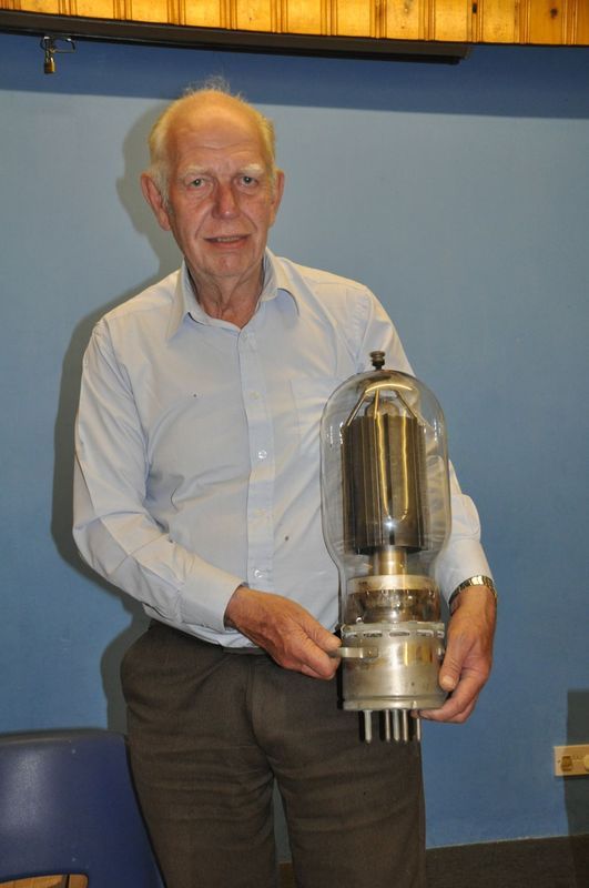
A picture of a vapour cooled transmitting valve - not sure if Alan has one in his collection. The picture shows one half of the modulator of a 250kW transmitter. It does have a tenuous connection to model engineering in that the valve sits on top of the boiler on an O ring about 9in. diameter and a quarter cross-section. These were originally neoprene, but changing to viton increased the life by a factor of 10, with a subsequent reduction in maintenance. I think Valves glowing always looks better than solid state but I did experience water-cooled transistors also.  |
|
|
|
Post by Deleted on Apr 28, 2015 8:38:05 GMT
Hi Tony ,
Very impressive those valves !
They must have needed electrical supplies which were high power , high voltage and very noise and ripple free - how was that done in days before high power semiconductor devices became available ?
MichaelW
|
|
|
|
Post by alanstepney on Apr 28, 2015 10:54:11 GMT
I do have some CAM and CAT valves and some very early air-cooled, but dont think that I have that paeticular one in my collection.
Before semiconductor rectifiers we used Mercury vapour, mercury arc, various other gases, and vacuum rectifiers.
Plus some large transmitting stations used rotary converters, basically an AC motor driving a DC generator.
On a smaller scale, we had selenium and metal oxide rectifiers, which were the forerunners of silicon.
Of course, the cats-whisker detector was a semiconductor so they have been around for a long time.
|
|
|
|
Post by steamlaser on Apr 28, 2015 22:22:53 GMT
A picture of a vapour cooled transmitting valve - not sure if Alan has one in his collection. The picture shows one half of the modulator of a 250kW transmitter. It does have a tenuous connection to model engineering in that the valve sits on top of the boiler on an O ring about 9in. diameter and a quarter cross-section. These were originally neoprene, but changing to viton increased the life by a factor of 10, with a subsequent reduction in maintenance. I think Valves glowing always looks better than solid state but I did experience water-cooled transistors also. Loved the picture of a real TX valve. I noted the substantial copper straps carrying the LT! The HT must have been running at a few mA. (:-) I bet it made your hair stand up if you touched the anode. We had a massive mobile RF welder at work which was water cooled. (It would have made a wonderful LF transmitter ) When it was scrapped I rescued the valve out of it and 35 years later it is still sitting in my loft. It makes a good exhibit to show people when I give talks on Radio. |
|
Tony K
Elder Statesman
Posts: 1,573
|
Post by Tony K on Apr 29, 2015 8:16:46 GMT
I do have some CAM and CAT valves and some very early air-cooled, but don't think I have that particular one in my collection. I am impressed! Hi Tony, Very impressive those valves! They must have needed electrical supplies which were high power , high voltage and very noise and ripple free - how was that done in days before high power semiconductor devices became available? MichaelW All true what Alan says. Until the era of the transmitter in the picture, DC in high current was needed for both the valve filament (heater) and the HT supply. HT had been supplied by motor/generators, mercury arcs (MARs) etc. and valves were water cooled. With this generation of transmitter, valves had AC filaments and HT derived from excitrons (like a single phase compact mercury arc and later easily replaced by solid state diode banks) plus vapour cooling. If you have an 11kV AC supply, use some puppetry with a transformer to effectively get 6 phase and use MARs, excitrons or solid state, then you can get DC with a small amplitude DC ripple which requires little smoothing. Then you can use just a big smoothing choke and one capacitor to smooth it. The heater had to be DC because of the induction of hum on the valve output from the AC. In the picture above, the valve has 4 filament terminals on the top. This is to take two separate AC feeds which are out of phase and the hum cancels, derived from a Scott transformer. The HT supply for the the RF output stage of the transmitter above is 11kV at 25 Amps to produce 250kW of RF (AM). The modulator you can see has to produce 125kW of audio to modulate the RF carrier to 100%. Do not forget that, near enough, anything you can do with a transistor you could do with a valve. Thus, series and shunt regulators using valves were very common when a regulated DC supply was needed. Most supplies are regulated now because it is so easy to do, but how many actually need it? MARs had the advantage of easily controlling the output but they were big and often constantly-pumped to achieve the vacuum. Finally, the beauty of the valve above was diminished when the glass envelope was replaced by ceramic, but that had to await the invention of beryllium ceramic with its temperature characteristics but with inherent safety risks. Just to give some scale to the picture, the photographer is standing on the floor looking in through an interlocked side door, the top of the picture is about 6 feet above the floor and the diameter of the valve glass envelope is about 12in. |
|
|
|
Post by alanstepney on Apr 29, 2015 17:08:22 GMT
I do have an excitron, an ignitron and some other high power rectifiers.
The electric railways used mercury arc rectifiers, to convert the AC mains to DC for the trains.
The Science Museum had a large mercury vapour rectifier which they used to fire up each dat for demonstrations.
Not sure if they still do.
The undersea-cable linking the National grid to the french electricity network uses DC with converters at the end to convert it to the voltage and frequency required.
|
|
|
|
Post by alanstepney on Apr 29, 2015 18:58:28 GMT
|
|
uuu
Elder Statesman
your message here...
Posts: 2,812
|
Post by uuu on Apr 30, 2015 7:05:54 GMT
 Here you are. |
|
|
|
Post by steamlaser on Apr 30, 2015 10:58:00 GMT
Now that Valve looks very similar to the one I loaned to the RSGB. I will have to send you a picture of my one. |
|
|
|
Post by alanstepney on Apr 30, 2015 11:10:40 GMT
Now that Valve looks very similar to the one I loaned to the RSGB. I will have to send you a picture of my one. Please do. The one I have (plus other similar ones) didnt come from the RSGB, but they do make interesting exhibits. Now, for those who are not interested in old valve, here is a problem. The Filament needs 32.5 volts at 460 Amps. (heavy wire, but relatively easy) the HT voltage ia 15,000 volts, at 10 Amps. (dont touch!) The anode is water cooled, using 20 gallons per minute. So, you have 20 galls / min, of water at close to boiling point, and with 15 kV on it. Now connect it some way (cant use copper pipes) so that it can flow to a cooling system, that will drop the temperature to, say, 60F and then it can be returned to the valve. |
|
|
|
Post by alanstepney on Apr 30, 2015 11:11:23 GMT
Here you are. Thanks. |
|
|
|
Post by Deleted on Apr 30, 2015 12:49:02 GMT
Thanks for all the information on valves and power systems .
I'm familiar with all of the power systems mentioned but in more rugged applications . I was quite surprised that something quite so agricultural as a mercury arc rectifier could be used for TV transmitter use .
As regards cooling HT anodes I'm sure there is a good answer to this coming !
If I had to design a system with no prior knowledge I'd probably think about using non conducting water and/or ceramic intercoolers .
Mention was made of Radio enthusiasts being members of Model Engineering clubs et al .
In the early days of course there was hardly any distiction - Marconi radios were more mechanical then electronic and there were many parts which could be made in home workshops .
Back on crystal sets . That kit of parts for a crystal set which Alan mentioned makes me think that something similar might work for model engines . A very basic engine in kit form which would work from a simple air supply (also a kit) or from communal boiler .
Anyone remember those cardboard cylinder in cylinder balloon pumps ? - they would work a small engine for a long time .
|
|
Tony K
Elder Statesman
Posts: 1,573
|
Post by Tony K on Apr 30, 2015 14:07:25 GMT
So, you have 20 galls/min, of water at close to boiling point, and with 15 kV on it.Now connect it some way (cant use copper pipes) so that it can flow to a cooling system, that will drop the temperature to, say, 60F and then it can be returned to the valve. PTFE or ceramic tubing and distilled or de-ionised water. Pass the hot water through a heat exchanger and use the heat to keep the building warm for those nice transmitter engineers. But, better to use vapour cooling for the anode as in my original picture above. ....Anyone remember those cardboard cylinder in cylinder balloon pumps? - they would work a small engine for a long time. Mmm!, maybe. Like this you mean? If I power an engine with it, I am not sure how I will blow up my balloons at Christmas then. Compressor I suppose.  |
|
|
|
Post by Deleted on May 3, 2015 13:10:52 GMT
Moving on logically from TV transmitters and early radio -
A lot of people years ago seemed to delight in making long and spectacular electric sparks .
Larger and larger Van Der Graaf generators and Tesla coils were built which generated higher and higher voltages .
Van Der Graaf and Tesla systems were of course completely different but both gave spectacular public performances !
|
|
|
|
Post by alanstepney on May 3, 2015 14:41:11 GMT
Moving on logically from TV transmitters and early radio - A lot of people years ago seemed to delight in making long and spectacular electric sparks . Larger and larger Van Der Graaf generators and Tesla coils were built which generated higher and higher voltages . Van Der Graaf and Tesla systems were of course completely different but both gave spectacular public performances ! You can see them at the Flight Refuelling Hamfest (9 August) some times at Poole Radio Society,and often at ther Amateur Radio shows / exhibtions. There used to be a display at the Science Museum, but not sure if it still exists. Meanwhile, yesterday I went to the Abbey Hill rally, at Yeovil. Well worth visiting. Apart from steam (various) there were classic bikes and cars, some nice models, and lost more to see. Just wish the weather had been warmer! |
|
|
|
Post by chris vine on May 3, 2015 21:15:36 GMT
|
|
|
|
Post by Deleted on May 5, 2015 16:41:22 GMT
They are always entertaining ! According to some sources the discharges have more energy in them than can be supplied by the Tesla coils . Numerous theories put forward for this . Take your choice : (a) Zero state energy being tapped . (b) Negative impedance effect during multiple initiations of ionisation . (c) Fusion of atom clusters at energy nodes . (d) Bad science and poor measurements . MichaelW |
|
|
|
Post by Deleted on May 5, 2015 16:50:28 GMT
Moving on logically from TV transmitters and early radio - A lot of people years ago seemed to delight in making long and spectacular electric sparks . Larger and larger Van Der Graaf generators and Tesla coils were built which generated higher and higher voltages . Van Der Graaf and Tesla systems were of course completely different but both gave spectacular public performances ! You can see them at the Flight Refuelling Hamfest (9 August) some times at Poole Radio Society,and often at ther Amateur Radio shows / exhibtions. There used to be a display at the Science Museum, but not sure if it still exists. Meanwhile, yesterday I went to the Abbey Hill rally, at Yeovil. Well worth visiting. Apart from steam (various) there were classic bikes and cars, some nice models, and lost more to see. Just wish the weather had been warmer! I had heard that there were quite a few of these machines around built by enthusiasts . Flight Refuelling brings back memories - I had six months placement there on project work many years ago . Excellent company to work with and beautiful part of the world . Went to several airshows at Yeovilton . MichaelW |
|
|
|
Post by alanstepney on May 5, 2015 19:07:11 GMT
You can see them at the Flight Refuelling Hamfest (9 August) some times at Poole Radio Society Flight Refuelling brings back memories - I had six months placement there on project work many years ago . Excellent company to work with and beautiful part of the world . Went to several airshows at Yeovilton . MichaelW Should you go to Hamfest this year (August 9th) look for me on the Poole Radio Society stand. There is also an active model railway club, which runs 5" ground level and will be operating that day.. |
|
|
|
Post by Deleted on May 7, 2015 16:20:37 GMT
|
|


