Greg
Involved Member

Posts: 84
|
Post by Greg on Sept 3, 2015 8:31:24 GMT
Hello,
I have part built Martin Evans Jubilee (2-6-4T) and have a problem with the build due to some errors with the drawings. I was hoping that someone might be able to help me out.
The chassis is almost complete, just the return cranks and eccentrics left to do. The problem is that the eccentric do no line up with the return crank. The eccentrics sit in about 5/32" to close to the frame. The engine is built accurately to the drawings. There are some known issues with the original drawings which I have recently become aware of. I have seen some engines part built where they have stopped at this point and also some engines with bent eccentrics to make it line up, but others have the eccentric fitting as it should. This suggests there's a solution to my problem, possibly the drawings have been amended.
Is there someone who has built one or know of someone that has they may be able to offer some assistance?
Thanks for your thoughts,
Greg
|
|
|
|
Post by donashton on Sept 3, 2015 10:46:19 GMT
Hi Greg,
Even on the full size engines it is rather rare to see an eccentric rod parallel to the mainframes, as generally the return crank end is further out than the expansion link tailpin. In plan view with the return crank pin to the rear must be clear, usually by part bending and part offset. As long as the length of the eccentric rod is correct all is fine.
Don.
|
|
Greg
Involved Member
Posts: 84
|
Post by Greg on Sept 4, 2015 23:31:56 GMT
Thanks for comments Don. I did trying bending one but it was quite ugly due to the size of the bend.My second thought was to shift the return cranks in further. I then realised after doing it that the crank pin would still be sticking out through the return crank and so that wouldn't work. I'm now thinking perhaps I could shift the cylinders out a little bit e.g.1.6-2mm. Here's my problem 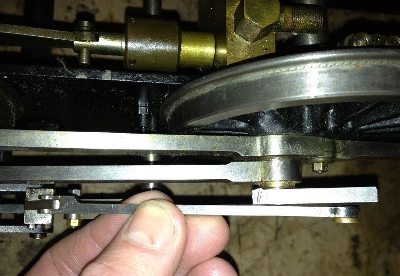 |
|
|
|
Post by runner42 on Sept 5, 2015 5:53:05 GMT
Wont shifting the cylinders out also push the crosshead out and affect it's alignment in the motion bracket, then affect the coupling rod having to move out also at the crosshead end and if the bearing at the crankpin end has little play cause the connecting rod to move farther out and exaggerate the problem with return crank and eccentric rod? The misalignment is very small and a slight bend in the eccentric rod should correct matters. Alternatively you can place a small bevel on the return crank at the crank pin to allow the eccentric rod to miss the return crank at the position shown, but this would cause the eccentric rod to be other than parallel to the return crank and affect the running of the eccentric rod bearing, so not a good idea. How do you propose to lock the return crank?
Brian |
|
Greg
Involved Member
Posts: 84
|
Post by Greg on Sept 5, 2015 6:59:43 GMT
Hi Brian, Yes the motion bracket would also have to be shifted out. I thought I could shift the cylinder and motion bracket out the same amount. The connecting rod would then also be out the same amount. Say I went with 1/16". I would then redo the connecting rod bush on the crank pin so that the majority of the shoulder on the bush was on the frame side. i.e. reduce the bush thickness where the arrow is. This would shift the big end of the connecting rod out 1/16" and keep it in aligment. The return crank would not need to shift out. How does that sound? I haven't yet decided how I'll lock the return cranks. At the moment there is a split at the bottom with a 6BA screw running through it to lock it. Greg  |
|
|
|
Post by Doug on Sept 5, 2015 7:09:22 GMT
Thanks for comments Don. I did trying bending one but it was quite ugly due to the size of the bend.My second thought was to shift the return cranks in further. I then realised after doing it that the crank pin would still be sticking out through the return crank and so that wouldn't work. I'm now thinking perhaps I could shift the cylinders out a little bit e.g.1.6-2mm. Here's my problem Hi Greg I have the same issue on my speedy however your problem looks quite acute the rod needs to be made offset this is obviously quite difficult on a manual mill I would suggest you start with some sheet material and bend it to shape and see what you have it only needs to get past the return crank before you can put the "set" in the rod. looking from above as in your photo with the return crank all the way backwards you should be able to setup the angles to clear see also Dons reply above I wouldn't recommend altering the motion you will almost certainly end up with even more issues. |
|
|
|
Post by donashton on Sept 5, 2015 7:25:49 GMT
Hi Greg,
That is no more than the usual amount found in Walschaerts' gear. If you start to redesign everything from the frame outwards you will constantly discover a good reason why it was placed where it is.
A simple kink just behind the forked end and one where the return crank corner is will do just like hundreds of others. Leave the route to disaster to others!
Don
|
|
Greg
Involved Member
Posts: 84
|
Post by Greg on Sept 5, 2015 8:06:20 GMT
I understand peoples concerns over fiddling with the motion, but have seen them built without the kinked eccentric and so know it's possible. oh yeah I forgot to mention one other concerning thing which could be a route to a big disaster. The clearance between the coupling rod and crosshead is not very healthy at about 0.003". The feeler even locks if I wobble the wheel  Apparently this was another problem with the drawings. I think no clearance here would be an even bigger risk than shifting the cylinder out a bit. Thoughts? 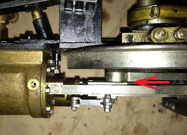 |
|
|
|
Post by donashton on Sept 5, 2015 9:21:26 GMT
Hi Greg,
0.003" is too close. The full size here was always tight for clearance, but not THAT close. I'm still unhappy about the major operation that you suggest on the aesthetic grounds of one lever. The last time I saw somebody rip all apart to 'rectify' a minor detail one thing led to another and it finished up being yanked down the road on a piece of rope by a young lad! It might sound like a joke, but the builder had become more and more disenchanted with the whole thing.
Wishing you well,
Don.
|
|
Greg
Involved Member
Posts: 84
|
Post by Greg on Sept 5, 2015 11:27:39 GMT
Hi Don,
I appreciate your thoughts and sentiments and don't disagree, but I know the bent eccentric would bother me and with also the tightness at the front end feel this would be a problem if I ever got to running it.
I've had this engine about 12 years. I'm sure it was sold because of this problem. Every few years I get it out from under the bench and have a bit of a go. I moved onto the plate work and have progressed it quiet a way because I wasn't sure how to sort the motion. I've seen a few running and so know it's possible.
I feel there's a solution out there that other Jubilee owners have found that I don't know of. I'd really like to finish it but have reached the point where I've decided if I can't finish the motion properly then I don't believe it's worth spending more time on it.
Greg
|
|
jma1009
Elder Statesman

Posts: 5,901
|
Post by jma1009 on Sept 5, 2015 13:30:53 GMT
hi greg,
you Jubilee looks to be very well made, and it would be a shame not to finish it.
i have dug out the relevant MEs for the construction series and drawings, and in respect of those ive looked at there is no mention of 'problems' with the eccentric rod. it was not uncommon for martin evans to make lots of errors but in the case of Jubilee he built the chassis at the same time the drawings appeared, and the photos of the chassis show he had built it with the valve gear by the time the 2 types of reverser were described.
the cylinder bore centre line is 1 1/32" from the mainframes, and the centre line of the expansion links and radius rods 1 3/8" from the mainframes. there are layout drawings showing all these dimensions.
there is a reference to the coupling rods fouling the crossheads unless the 1/32" gasket is added between cylinders and mainframes. so the clearance here is less than 1/32"!
part of the front/outer face of the return crank is relieved by 8 thou, and the outer face of the return crank is shown as 1 3/8" from the mainframes.
if you have all the drawings it shouldnt be too difficult to find out where the error has arisen.
packing out the cylinders (and motion bracket) will result in the conn rods being at an angle, and you will need to remake the weighshaft and lifting arms.
i would check very carefully that the cylinder bores and piston rods are parallel to the mainframes. a slight error in machining the backs of the cylinder blocks would result in an alteration to the width/centres of the motion brackets to compensate, and throw everything out.
cheers,
julian
|
|
|
|
Post by alanstepney on Sept 5, 2015 15:10:27 GMT
I started (and almost finished) a Jubilee some time ago. It then was stored in sons garage where it collected a thin layer of rust.
It is now here and had to be completely dismantled. Each part is being cleaned off, de-rusted and then put safely aside ready for assembly (again).
I dont recall any problems with the valve gear / motion, or clearances.
When finished they are an excellent loco, run well and haul a surprising number of passengers.
Keep going the problem cant be insurmountable.
|
|
|
|
Post by chris vine on Sept 5, 2015 20:46:55 GMT
Hi Greg,
One of your problems is that the cross-head nearly fouls the coupling rod. Why not machine a bit off the back of the cross-head - The back doesn't really do anything??
I think a lot of eccentric rods are cranked, like yours looks like it needs. You might find that you can achieve what you want by splitting lots of differences: A bit of a crank, maybe put in a 1/32 gasket behind the cylinder block, move the return crank in a smidgen (The big end bush could lose a bit, if you can shorten the crank-pin a fraction). In short, you may be able to achieve 1/8" by 4 different 1/32". Or 3 different 1/32" and have the eccentric rod crooked by 1/32" you will never see that!!
Chris.
|
|
Greg
Involved Member
Posts: 84
|
Post by Greg on Sept 6, 2015 1:27:08 GMT
Thanks everyone for all your suggestions. Hi Julian, yes it has been very well made and it would be a shame not to finish. Thanks for digging out your old MEs and having a look through them. I have a copy of most of the Jublee articles and also a full size set of drawings. My engine has the 1/32" packer between the cylinder and frame. I have checked the drawings and I believe I know where the error lies. If you look at the plan drawing it shows all the motion in correct alignment. However the return crank is wrongly drawn the same thickness as the eccentric which is 1/8" The return crank is not the same width, it's 3/16" So there's the 1/16" or so I'm out. Hi Alan, interesting that yours went together ok. Is your eccentric straight? It's good to find someone that's making one. I agree that it should be a very good runner. I club member has a William and that runs very well. So with a slightly larger boiler and wheels is should be very nice when it's done. Hi Chris, the inside of the crosshead isn't that thick and so not a lot that could be taken off it, but I think you're right I'll just have to do some tweaking in a few places to get the alignment a little closer. The eccentric may end up with a slight bend, which I should be able to live with if it's not obvious. Here's the dimensions of mine compared with the plan. The only thing a little out with mine is the inside of the return crank is 0.010" further out.  |
|
|
|
Post by runner42 on Sept 6, 2015 7:44:12 GMT
I don't know if this is relevant but my analysis of designs is that the designers appear to work in multiplies of a 1/32" or occasionally in 1/64" and not specify an exact decimal measurement nor nominate a tolerance for that measurement, such that builders sometimes in complex design such as valve gear motion work produce a number of measurements where the tolerances all work in one direction and produce errors that are significant. A few thousandth of an inch can cause severe binding. So it appears that (maybe unwritten in words and music) more emphasis needs to be placed on the "fitting" part of ME, what I mean by this is doing the necessary to make it work. That has been my experience, maybe due to my measurement accuracy being only to +/- 0.001" which was probably the average capability of MEs in the early days before CNC and DROs.
Brian |
|
Greg
Involved Member
Posts: 84
|
Post by Greg on Sept 6, 2015 8:53:29 GMT
I suspect you're right Brian and in my case its all come together at the eccentric. I had a bit of a fiddle and think I have a solution. Against peoples advice I have tried moving the cylinder out 0.040". Apologies as I've probably come across as a another new guy that doesn't listen to advice from the experienced. I put a 0.040" packer between the cylinder and frame and also under the motion bracket. At teh moment the lifting arms are only held onto the weighshaft with grub screws and so it was no problem sliding the lifting arm out 0.040". Moving the cylinder out gave me a healthy clearance between the rear of the cross head and the front wheel. So this places the connecting rod out 0.040". Obviously it should really be parallel. I looked at the big end bush and I can offset it so that the rod sits further out, but the bush is no wider and it still fits on the crank. The drawing of the proposed bush is below. I may still need a very slight bend on the eccentric, but don't think it'll be noticeable. Does this all sound ok or have I overlooked something?  |
|
jma1009
Elder Statesman
Posts: 5,901
|
Post by jma1009 on Sept 6, 2015 8:58:50 GMT
hi greg,
i would say that the return crank thinkness on the layout drawing of the gear is shown as being more than 1/8". i havent added up all the widths on the various drawings of the parts to check the 1 3/8" measurement.
there needs to be sideplay on the wheelsets when the axleboxes are fitted in the horns, and this needs to be allowed for when dealing with clearances between parts. i think sideplay is often excessive and i reduce it to the bare minimum to allow the axles to tilt. in your case you need to take into account any sideplay as im sure you have done.
i dont think you can machine much off the backs of the crossheads. things are definitely tight here and you need more clearance. the easiest way would be to replace the 1/32" Hallite sheet with a piece of 1/16" or 3/32" steel sheet, depending on the sideplay on your front wheelset.
my 3.5"g GWR King has the cylinder bore centre 1 1/16" from the mainframe, and things are decidedly tight between back of crosshead and front coupling rod despite having 'finescale' wheels of narrower tread than standard.
i would add a similar thickness of packing to the motion brackets, and remake the weighshaft longer to suit. you might be able to re-use the weighshaft arm and lifting arms. this extra clearance will also assist in a tight clearance between the lifting arms and conn rods.
you will need to have a bend in the eccentric rod but if carefully done gradually over the first 2" shouldnt be noticeable. in theory new eccentric rods of the correct lengths will be required.
by altering the depth of the conn rods on their bushes the 'off parallel' conn rods with the above modifications can be minimised.
cheers,
julian
|
|
jma1009
Elder Statesman
Posts: 5,901
|
Post by jma1009 on Sept 6, 2015 9:01:30 GMT
hi greg,
our posts above at same time! what you are proposing is what i have pretty much suggested above.
cheers,
julian
|
|
Greg
Involved Member
Posts: 84
|
Post by Greg on Sept 6, 2015 9:29:06 GMT
Hi Julian, It sounds like we have a plan.  I'll continue on and hopefully it all comes together. Thanks everyone for your suggestions. Greg |
|
|
|
Post by alanstepney on Sept 6, 2015 11:41:18 GMT
I dont recall any specific problems but it was some time ago, and if I found a problem, obviously found a way round it.
As for measurements, when that design appeared very VERY few people would have owned a micrometer.
They cost over a weeks average wage!
You might be able to read the 64ths on a rule, perhaps even read the 100ths, if you have very good eyesight, but even then, you have to mark out and cut to that measurement. It was taken for granted that some fitting would be required, and that was too common to even mention.
Now, when measuring implements are cheap and everyone has some, it becomes a problem as people expect things to just fit together. They dont.
|
|


 Apparently this was another problem with the drawings. I think no clearance here would be an even bigger risk than shifting the cylinder out a bit.
 I'll continue on and hopefully it all comes together.