|
|
Post by Roger on Sept 18, 2015 19:46:30 GMT
Thanks for that Joan, it does sound like an auto optimisation in the assembly view. I imagine you can change that in the preferences. My system relies on the display attributes when creating the tool paths, and that seems amateurish software design to me. Still, it works and you only have to make sure the default it to 'Fine' then any new jobs are automatically correct.
It's interesting what you say about the 2D drawings and tolerances. If you look in the dimension attributes for a particular dimension on your CAD system, probably using a right mouse click, you will almost certainly be able to override the default dimension and change it to one with a variety of options. Those might include Lettered fits H7 for example and +/- tolerances. That's the best way to let the subcontractor know what's important. In the title block, I'd use a general tolerance of say +/- 0.1mm and also define the geometric tolerances you can accept overall. You can also use geometric tolerancing on the drawing if necessary. The drawing ought to speak for itself really, it's dangerous to use nominal dimensions where something is important.
|
|
|
|
Post by joanlluch on Sept 18, 2015 20:44:12 GMT
Hi Roger,
Yes, that's definitely an optimisation on the assembly view. My main assembly -the one showing the entire locomotive with tender- has already 1710 parts in 275 sub-assemblies with 359 unique parts. I suppose this is not that much for what could be usual in the productive world, so it still moves and rotates very fast. Well, I'm using powerful Apple hardware, but still. Since you will almost always work on a reduced set of parts at any given time, the entire assembly still moves very fast and keeps you moving around very fast. (not that I am any productive with the software, but you get the idea) . However, you can stress the environment by opening lots of unrelated parts on unrelated subassemblies. Models will still keep moving fast, but at some point you start to feel some slight sluggishness when switching windows. I think this is related to emptying the graphics processor memory and loading larger display polygons in it. However, once the graphics processor gets fed with what it must display, the model moves quickly again.
About tolerances, it is just like you say. I use those options on dimensions to add tolerances next to them. I mostly use ISO tolerances (such as h7, g6 or H7 and so on) when some kind of fit is required (axle and wheel is the most obvious case), but I have also specified something as coarse as +0.0/+0.1 for things such as the axle passage holes on axle box covers to indicate that the actual dimension does not need to be accurate.
However, my short experience on this has taught me that it's always a good thing to actually talk with the service to let them know and understand how several parts are meant to be assembled together, and for as much as possible I try to order the parts that will fit together in a single order, because in case something goes wrong it is much easier to see it by simply attempting an assembly of the same parts.
|
|
|
|
Post by Roger on Sept 18, 2015 20:56:13 GMT
Hi Joan,
I think your software is a lot better written than mine, I have issues with the whole house of cards coming down when too many things are open and I'm copying and pasting things. I'm sure it's memory management issues, but the software suppliers seem unwilling to accept there are issues so they don't fix them.
I'm also a fan of talking to the people who I want to use as sub-contractors, not that I do it often. There's nothing quite like stressing what's important even though it's well defined on the drawing.
|
|
|
|
Post by joanlluch on Sept 18, 2015 21:39:57 GMT
Hi Joan, I think your software is a lot better written than mine, I have issues with the whole house of cards coming down when too many things are open and I'm copying and pasting things. I'm sure it's memory management issues, but the software suppliers seem unwilling to accept there are issues so they don't fix them. I'm also a fan of talking to the people who I want to use as sub-contractors, not that I do it often. There's nothing quite like stressing what's important even though it's well defined on the drawing. I experienced a similar issue -the CAD environment crashing- at some point of my loco development. I am using Solid Edge ST6. The software worked fine until I reached a particular number of parts or complexity (or something), but after some point it turned unusable due to continuos crashes, specially after switching windows. After weeks of frustration I found a fix by googling the issue. In my case it turned to be a defective setting on the "Application Display" settings. By default it was set to "Graphic card driven (Basic)". I switched that to "Graphic card driven (Advanced)" and checked "Use display lists". Suddenly, the software turned into a different beast. A lot more responsible, fast moving, and no crashes at all. Currently, it still crashes sometimes in the 2D drawing environment, but never while modelling in 3D which is where I am most of the time. At the time I changed the setting, I barely had the frames and the axle boxes with wheels drawn, and now with almost the entire loco modelled the software still feels very fast and responsible. Maybe this gives you some clue about what to look at, I would be very surprised that a commercial software that possibly is not anything near cheap would not work as you would expect. |
|
|
|
Post by Roger on Sept 19, 2015 6:44:56 GMT
I know there are memory management issues, I can see it eating up way too much memory when I look at it in the 'Task manager'. Mine also tends to be fragile if I open two separate parts and then copy and paste sketches from one to the other. It also doesn't always release the memory when the part is closed. You have to close the Menu front end program before it does that. They're in denial about this even though I sent them very specific instances demonstrating the issues. They tell me that the garbage collection is automatic so it isn't an issue, but they're wrong, it doesn't always work. Unfortunately, software developers are not really interested in chasing down bugs, they'd rather play with making new features we don't want!
|
|
|
|
Post by joanlluch on Sept 19, 2015 7:04:02 GMT
Hi Roger, what software are you using?. I recall Adam uses SolidWorks which I think is the most extended one. I'm on Solid Edge just because a friend of mine used it and taught me the most basic concepts. I'm very pleased with it.
|
|
|
|
Post by Roger on Sept 19, 2015 7:12:07 GMT
I'm using Geomagic Design, originally called Alibre Design. On the whole, it's very good, but there are these serious bugs that are an occasional annoyance. I just wish they'd get their act together and sort out the crashing issues.
|
|
|
|
Post by joanlluch on Sept 19, 2015 15:22:26 GMT
I'm using Geomagic Design, originally called Alibre Design. On the whole, it's very good, but there are these serious bugs that are an occasional annoyance. I just wish they'd get their act together and sort out the crashing issues. I've looked at their web site and it seems to have all what is needed, so it's a pity if it has some flaws. The software I am using is totally overkill for my needs and my skills, as there are hundreds of options that I can't even imagine what are they for. However, Solid Edge has a feature that I couldn't live without. They call it "Synchronous Technology". As fas as I know Solid Edge is the only CAD in the market incorporating this feature. Let me try to expose what it is about: Traditional 3D CAD modelling is based on drawing 2D sketches that you use as a basis to add 3D features to 3D parts, such as protrusions, holes, revolutions and so on. In traditional CAD, sketches and features will remain linked to the 3D part, and the order you applied them actually defines the part. Complex parts are thus described by a series of operations in a row that are applied in order from start to finish. On the contrary, the "Synchronous" environment of Solid Edge liberates you from this "ordered" way of modelling and allows you to create 3D parts in a freer way. Basically, you can modify parts on the fly, in a visual way, and with full independence of how you actually made them. You still use sketches to apply features to parts, but sketches are removed from the part and features are automatically related to other features based on geometrical 'rules', such as symmetries, diameters, lengths, centres, tangents, planes, and so on. The software keeps part features synced together by said 'rules' with independence of how you actually created the part. In fact the way you created the part is irrelevant. By enabling or disabling the particular 'rules' that interest you at any time, you can create or edit features of the part directly, in a very straightforward way. Not everything can be drawn in the "Synchonous" environment, as there are still a few exceptions, but I have made 99% of the loco in this way. |
|
|
|
Post by joanlluch on Sept 19, 2015 16:17:09 GMT
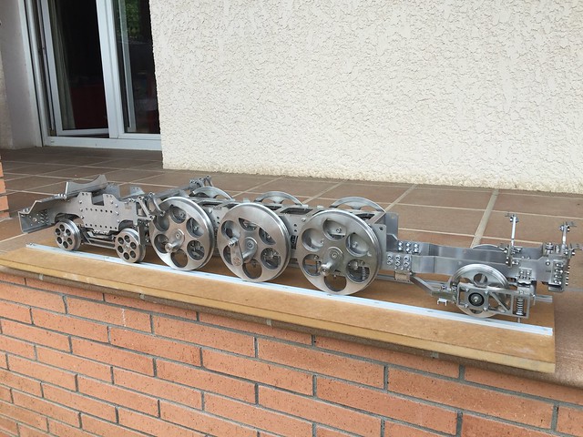
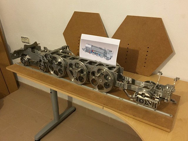
PONY TRUCK Before going for the valve gear description, I thought it would be better to briefly describe the locomotive pony truck. In reality, the gear was one of the first subjects I worked on because somehow I believed it could be the most challenging aspect of the loco. But then I eventually made the pony truck earlier than the gear. So it's better to show the truck now because it appears in several build photos without the valve gear in place yet. First of all, I want to post a view of it from the bottom of the locomotive: 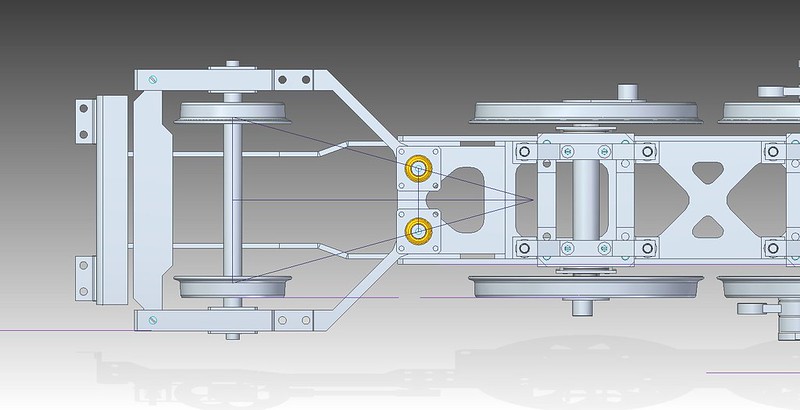 WheelBaseAssembly-Pony WheelBaseAssembly-Pony by joan lluch, on Flickr And this is how it looks with perspective 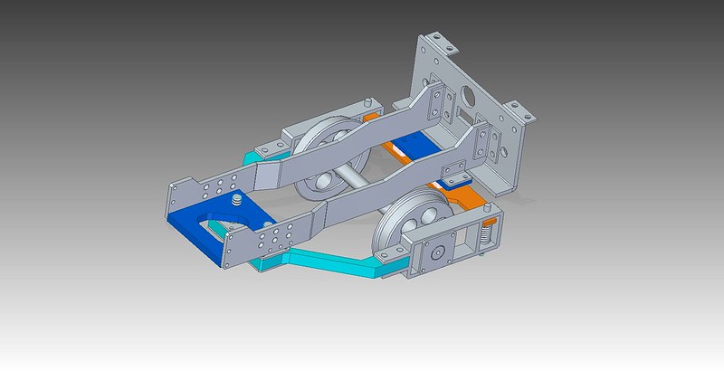 PonyAssembly PonyAssembly by joan lluch, on Flickr It differs from the usual -single pivot based- designs on the following aspects: - Instead of the traditional single pivot, my pony truck design has two of them. The actual, or virtual, centre of rotation goes exactly at a point that is located at half distance between the central driving axle and the pony truck axle. This is the correct pivot point location accepted for a 'pacific' configuration locomotive. Traditional designs do not usually met this criteria because it is not generally possible to place a single pivot point at just the right place due to space constraints. - The truck has two lateral 'arms' that move independently from each other but together with the wheels (cyan colour) [the cyan colour should extend to the part that has the bearings, but you get the idea]. Arms are fixed to the frames (dark blue) by spherical bearings (yellow) at one side and to the wheel axle through auto-aligning bearings towards the centre of the arms. At the rear, the arms are linked through springs to a subframe (orange), which in turn is supported to the frames by plastic sliding pads (white). The resulting mechanism has all the required degrees of freedom required to perform its function. A pair of extension springs (not shown) keep the pony truck centred to the locomotive longitudinal axis. - The design avoids the need for axle boxes or complex sliding surfaces, thus removing the need for maintenance or oiling. |
|
|
|
Post by joanlluch on Sept 19, 2015 16:24:47 GMT
This is an 'exploded' view of the Pony Truck as drawn in the 3D CAD environment 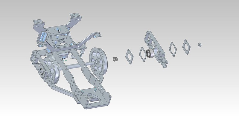 PonyAssembly PonyAssembly by joan lluch, on Flickr |
|
|
|
Post by joanlluch on Sept 19, 2015 16:33:30 GMT
The truck as drawn was difficult to test and simulate in the CAD environment without adding some artificial constraints that allowed it to move, so I missed an important aspect that created an issue in the real thing. It's difficult to describe it in words, but basically, the fact that the pivoting edge of one arm, the wheel bearing, and the spring are not on the same vertical plane caused the arm to tilt when it is subjected to the locomotive weight, which ultimately made it to work in an unexpected way. The solution for that issue was adding a flexible strap (dark blue) between the arms that would fix the distance between them and prevent them to tilt in undesired ways. This is the proposed final design. 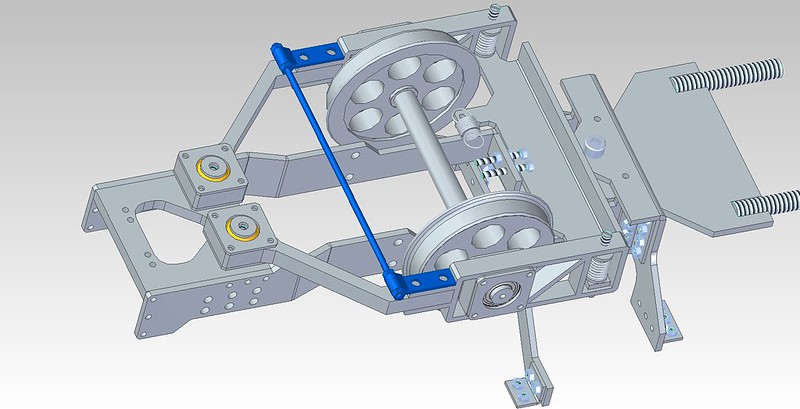 PonyAssemblyStabilizer PonyAssemblyStabilizer by joan lluch, on Flickr This has not yet implemented in the real thing, but it was tested to work by using a temporary fix that will be replaced by the final design as soon as I make my next order of laser cut parts. |
|
|
|
Post by joanlluch on Sept 19, 2015 16:38:00 GMT
|
|
|
|
Post by joanlluch on Sept 19, 2015 17:01:49 GMT
VALVE GEAR DESIGN Ok, so now it's time to describe my valve gear. As stated at the beginning of the thread I chose the "Baker" valve gear for my locomotive. The Baker gear is geometrically similar to Walschaerts in the sense that it features a combination lever, a return crank, and an eccentric rod. However, the Expansion Link is replaced by a mechanism which is slightly more complex, but has only rotating parts in it. Since this kind of gear was rarely used elsewhere than the USA, I think it's useful to start by posting a picture about how the main mechanism looked in full size: 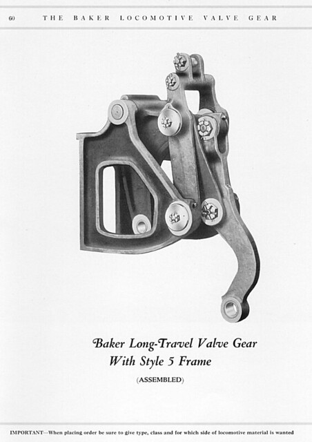 parts_60_style_5 parts_60_style_5 by joan lluch, on Flickr I chose it because maintenance should be easier without the need to re-make any parts. The only parts subjected to wear are the bearings, which are easily replaceable. |
|
|
|
Post by joanlluch on Sept 19, 2015 17:53:47 GMT
To design the basic geometry of my locomotive valve gear geometry I used 2D CAD draftings, and followed the procedure below: (1)- I started by assuming some arbitrary dimensions for the valve gear mechanism which provided the desired valve travel. (2)- To design the combination lever I drew a triangle with half the stroke at its base, and used the vertical distance between piston axle and piston valve as well as the lap+lead. I geometrically determined the combination lever dimensions. This is independent of 1 (3)- 1 and 2 gave me the length of the valve rod. (4)- On a second draft I drew the relative positions of the main axle and the tail pin in mid gear. This gave me the right angle and length of the combination lever as well as the length of the eccentric rod. (5)- I tested the proposed geometry to work on the Allan Wallace simulator and applied minor adjustments on the length of the combination lever, valve rod, and eccentric rod to get the best possible events. I eventually repeated the process with several proposals for (1) until I found the one that fully satisfied me. My final choice gives very good valve events for forward motion and fairly good for reverse gear. The following picture shows the diagrams of one of my intermediate designs, as I did not take a picture of the final one. 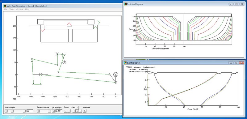 bakerc bakerc by joan lluch, on Flickr |
|
|
|
Post by joanlluch on Sept 19, 2015 17:59:04 GMT
At some time I captured a some vids with the gear moving in the CAD model. Forward: See it on YouTube : youtu.be/0b-QmrQeeK0 Reverse: See it on YouTube: youtu.be/FntiApAK_n8Watching a steam locomotive moving is pure "mechanical poetry" in my opinion. |
|
|
|
Post by joanlluch on Sept 19, 2015 18:17:36 GMT
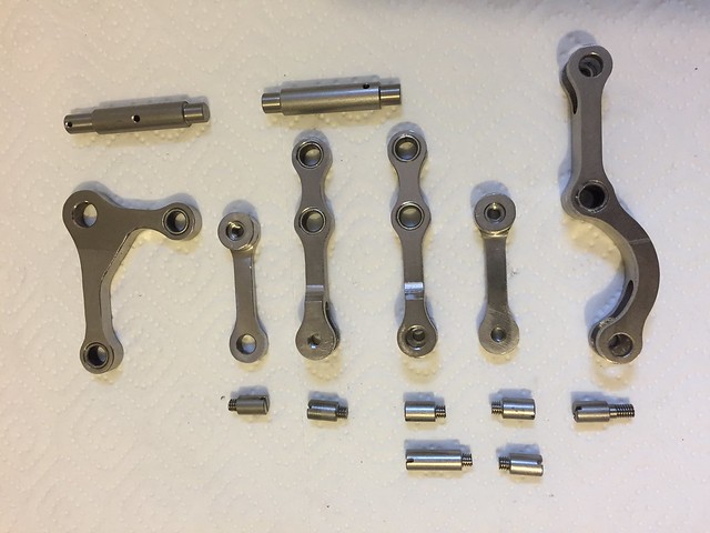
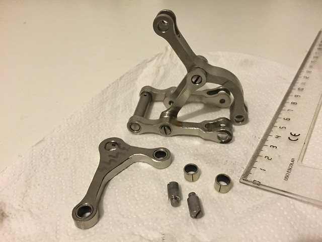
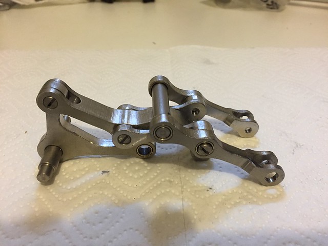
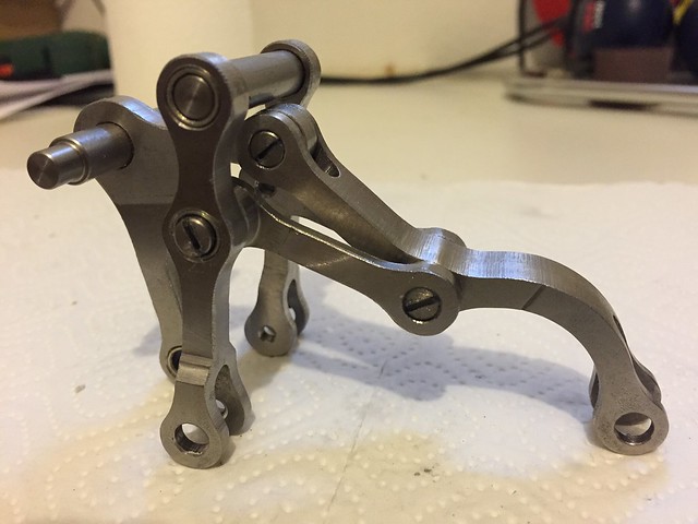
CONNECTION RODS, COUPLING RODS, AND VALVE GEAR. So now it is time for some *real* stuff. These are the rods already machined including the valve gear mechanism: 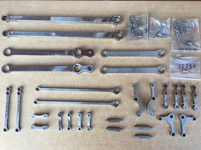 Vieles Vieles by joan lluch, on Flickr I am using commercially available Bronze-PTFE based plain bearings from SKF or INA for all the rods. Such as these ones: 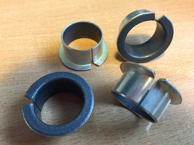 Coixinets Plans Coixinets Plans by joan lluch, on Flickr Tolerances of the rod housing holes diameters and pins are very important for a smooth running with no gaps. The manufacturer recommends h7 for shafts (or pins) and H7 for the housings. I found that this still creates a very slight interference after assembly, which quickly disappears after use. This kind of bearings are supposed to work long time without lubrication, but of course that's an unknown at this time. Time will tell, how reliable or durable are they. They look like this after pushed into their housings at the end of rods. 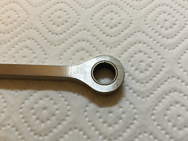 Distribució Distribució by joan lluch, on Flickr 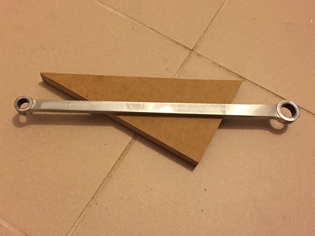 Vieles Vieles by joan lluch, on Flickr |
|
|
|
Post by joanlluch on Sept 19, 2015 18:25:24 GMT
|
|
|
|
Post by joanlluch on Sept 19, 2015 18:26:30 GMT
|
|
|
|
Post by joanlluch on Sept 19, 2015 18:29:37 GMT
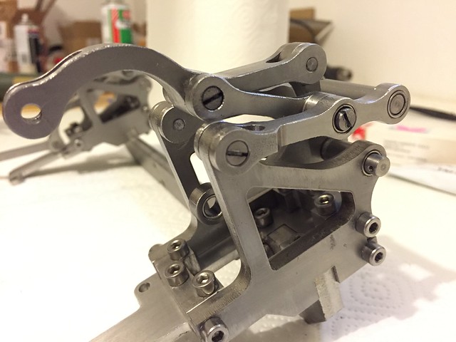
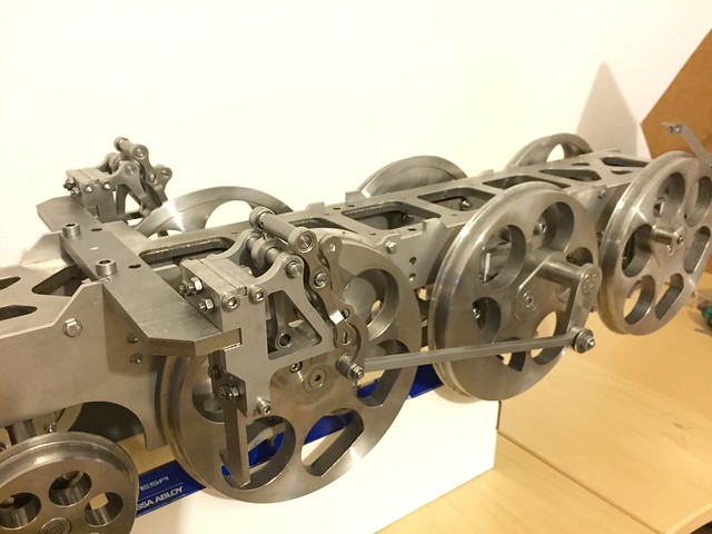
And now with the connection rod and coupling rods as well. 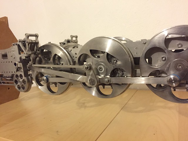 Vieles Vieles by joan lluch, on Flickr |
|
|
|
Post by donashton on Sept 19, 2015 19:26:51 GMT
Hi Joan,
I can agree with your 'mechanical poetry' once you have figured out the valve gear but quite often a set is reluctant to get each stanza to rhyme! This is hardly to be expected and is neatly illustrated in the design of the combination lever using two similar triangles. They may be fairly similar but are certainly not triangular. However, this is not criticism, it is a warning to the novice that things need a little openness of mind. Since front and rear strokes of a double acting cylinder are not the same it is as well that we have a number of places in the mechanism where optimisation can take place.
All that complicates the learning curve. Joan you have managed a degree of familiarity in a rather short time and deserve acknowledgement. The first results of input often frustrate! Once you have a full mechanism there is plenty to do before the fine tuning satisfies. In this respect it is worth pointing out one or two things in the diagrams.
Firstly, top right indicator diagrams, we see at a quick glance how symmetrical events are. Secondly (as Prof. Bill Hall discovered), inlet pressure at the opening of the port is for a model immediate. So too is the pressure drop at release.
Cheers,
Don.
|
|