|
|
Post by joanlluch on Sept 19, 2015 19:43:23 GMT
So that's all for now. This is the stage the locomotive is at this time. 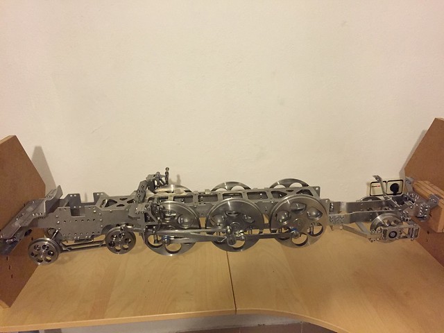 Vieles Vieles by joan lluch, on Flickr For what can be tested so far, the valve gear is doing what it is meant to, both in forward and reverse, and everything else is going just fine. The locomotive wheels rotate smoothly with no hard spots or jerkiness. I have put special effort in making sure that everything that could affect frame parallelism, distance between wheels, and actual position of crank pins was correct. The required accuracy was achieved though this: 1- Frames were laser cut and included housing for the axle box horns. Although laser cut parts are meant to have a dimensional accuracy of only +-0.05 mm, the reality (actual fact) is that reproducibly is much better. This means that if you place a series of identical features such as holes, or cuts, all of them will be cut the same way and their relative placement will be very precise. I used that property for two purposes. (a) Axle box horns were inserted into identical -omega shaped- cuts on the frames. (b) the front of the loco has features that position both frames in fully symmetrical position. 2- Axle box horns inner and outer surfaces were machined in a single CNC setup, and all of them using the same CNC program and tools. This made them identical, the inner surfaces became precisely centred with respect to the outer -omega shaped- ones that mate with the frame cuts. 3 - Axle boxes relevant faces were machined in a single CNC mill setup. In particular bearing housings and sliding surfaces were made on the same setup by the CNC mill, not with a lathe. So all axle boxes are identical and bearing housings are just at the precise middle distance between the sliding surfaces. 4 - Plastic (Ertalite TX) is used for the sliding surfaces. To create the proper sliding feel some filing was needed. This was the only single source where some inaccuracy could be introduced, but I payed attention to measure the width of the pads at all times. 5 - Coupling rods bearing housings were made in a single CNC mill setup, thus the distance between centres is highly accurate. -- No assembly dimension has been checked at any time. I just relied on the parts being made as described. -- None of the traditional methods or tools that are applied to position frames, axle horns, or to machine them together has been used. |
|
|
|
Post by andyhigham on Sept 19, 2015 20:06:09 GMT
I remember being told as an apprentice a story about Rover cars manufacturing Rolls Royce engines during the war. Rover sent the drawings back to RR with a request to "tighten up the tolerances"
Rolls Royce had used methods familiar to model engineers where parts were made and adjusted to fit. Rover used more modern methods, parts were made to a standard and assembled. Joans method is essentially the same, as is virtually all modern production engineering
|
|
|
|
Post by joanlluch on Sept 19, 2015 20:19:24 GMT
I remember being told as an apprentice a story about Rover cars manufacturing Rolls Royce engines during the war. Rover sent the drawings back to RR with a request to "tighten up the tolerances" Rolls Royce had used methods familiar to model engineers where parts were made and adjusted to fit. Rover used more modern methods, parts were made to a standard and assembled. Joans method is essentially the same, as is virtually all modern production engineering Yes, exactly. Anything that is produced in big series is made according to tight tolerances and the less assembly adjustments required the better. A mini locomotive is of course never meant to be manufactured as a series, but since I used CNC and I had complete freedom to design my own parts I made them in a way that "modern" manufacturing was possible. |
|
|
|
Post by Roger on Sept 19, 2015 20:22:32 GMT
Hi Joan,
Thanks for that explanation of synchronous design, it's certainly very different to the sequential way it's done in Geomagic Design. I can certainly see advantages in doing things that way.
|
|
|
|
Post by joanlluch on Sept 19, 2015 21:47:43 GMT
Hi Joan, I can agree with your 'mechanical poetry' once you have figured out the valve gear but quite often a set is reluctant to get each stanza to rhyme! This is hardly to be expected and is neatly illustrated in the design of the combination lever using two similar triangles. They may be fairly similar but are certainly not triangular. However, this is not criticism, it is a warning to the novice that things need a little openness of mind. Since front and rear strokes of a double acting cylinder are not the same it is as well that we have a number of places in the mechanism where optimisation can take place. Cheers, Don. Hi Don. I think that I see what you mean. What I actually did is to use a trapezium as a geometrical way to compute the two lengths of the combination lever. Up to this point this is the same as applying a proportional equation between mid stroke, vertical distance 'lower arm-valve', and lap+lead, as the formula shown in Fig.6, page 6 of your book. I just did the same in a geometrical way by using the precision of CAD dimensions, which gives the same result. I understand that the way to compute this does not have to do with the fact that the central point between the front and rear strokes is, well, not in the middle of the two. In practice the combination lever is not fully vertical at mid gear and mid stroke (which as said, it's because it does not happen to be the same as half stroke) As you know, I experimented a lot with the Baker mechanism, and I found that it being more complex than a Waltshaerts expansion link, it offers some additional opportunities to compensate inequalities of the remaining components if you deliberately make the mechanism to produce opposite inequalities. I found one particular arrangement that created forward events almost as fine as the Stephenson gear, and possibly better than what is possible with Walschaerts (I may be wrong with the latter). However, since this was achieved by introducing explicit inequalities on the mechanism, it failed to produce anything acceptable on reverse. So at the end I just made the Baker mechanism dimensionally balanced and adjusted the rest of the gear as if it was a Walschaerts. |
|
jma1009
Elder Statesman

Posts: 5,901
|
Post by jma1009 on Sept 19, 2015 23:30:35 GMT
hi joan
i have it on good authority that your Baker valve gear is extremely well worked out. that is quite a significant achievement for which you deserve considerable praise.
cheers,
julian
|
|
|
|
Post by joanlluch on Sept 20, 2015 7:09:44 GMT
Hi Joan, Thanks for that explanation of synchronous design, it's certainly very different to the sequential way it's done in Geomagic Design. I can certainly see advantages in doing things that way. Hi Roger, I think that both aproaches have unique advantages. Solid Edge allows you to draw parts in any of the two. The sequential way is called "ordered" and the free drawing one is called "synchronous". You can place "ordered" features in a "synchronous" part, but not the opposite. I have not mastered this thought, it's rather confusing to me. The advantage of pure "ordered" parts, is that they can be parameterised and you can even give external variables to them. For example, you can draw a generic spring in the 'ordered' environment and make it any size by just changing the number of turns and its diameter. Additionally, you can set its height as a variable. In an assembly, you can place the spring in a way that its height is made dependent on other parts. By doing this you get the spring actually (dimensionally) springing in the assembly. Nothing of this could be done for a spring drawn in the "synchronous" environment because in this case there's no notion of parameters. It's just a static shape. A synchronous part is no more than a shape in the 3D space which does not have global parameters. You can edit the part as you want, and that's pretty easy, for example I can make a rod shorter or longer, but it does not have parameters in the way that an 'ordered' part would have. |
|
|
|
Post by Roger on Sept 20, 2015 7:25:18 GMT
Hi Joan,
That makes sense, and I do have some parts where it's useful to have parameters, for example, my cap screws are drawn using parameters. As an aside, there's a scripting tool that someone has created, which allows all of the drawing commands to be accessed from a script. Using that technique, you could auto generate simple shapes on demand, for example nuts, bolts and washers of any size. It's not something I can imagine myself bothering with, but it's another example of the usefulness of sequential design. I've not played with the synchronous type so I don't know whether I'd get on with it or not. It's taken me long enough to get to grips with the sequential method, finding the best way to create shapes with CAM output in mind. Presumably you'd have to create sketches from a synchronous model else you wouldn't have any reference geometry for 2D tool paths. Doubtless they've thought all of this through when developing that method.
|
|
|
|
Post by joanlluch on Sept 20, 2015 7:27:04 GMT
hi joan i have it on good authority that your Baker valve gear is extremely well worked out. that is quite a significant achievement for which you deserve considerable praise. cheers, julian Hi Julian, thanks for your message. I have been sharing my work with Don and he approved it. However, I do not think that this is such a great accomplishment because I basically followed Don's book "Design Procedures for Walschaerts' and Stephenson's Valve Gears", which I can't cease to recommend to all Model Engineers who want to understand and learn about how their valve gear works. I think it's Don Ashton for having written such an excellent book who deserves it all. Also, the use of Allan Wallace simulator -despite its occasional glitches- was key to fully optimise the final geometry and to choose the one that offered the best balance of forward/reverse events among the several ones that I tested. |
|
|
|
Post by joanlluch on Sept 20, 2015 7:59:39 GMT
Hi Roger,
Well, as you know I'm not an expert, but what you say makes a lot of sense. I know that such a 'scripting' language is also available in Solid Edge, but at my age that's already over my head. I'm sure I would have messed with it if I had worked with CAD at my 20's, but I just learned CAD one year ago and I'm still struggling with it. I am not aware of the way you create CAM output, but I would be surprised if that could not be done for "synchronous" parts because that way of drawing is what's been pushed by the manufacturer.
About what's easier, well, to me the synchronous environment wins all the comparisons. Once you get used to it you never want to go back. Its biggest advantage is that parts are not linked to the sketches you used to make them, and instead the resulting features are linked among them by implicit rules. You work on the part as a shape in the 3D Space regardless of how it's made, and you can perform any edits on it as lazily as you want. I have worked less with the ordered environment but I can imagine situations like this: you draw a part with very complex features in one end. Then you decide to cut the part by half thus removing most of its complexity. If the part is ordered I think that all the features that were there will still be. It's still a complex part which happens to have a cut in the middle. However, if the part is synchronous, it will become much simpler after the cut, as only some simple features will remain in it. That's the power or going synchronous, parts do not have a history, they are just 3D shapes in the space.
|
|
|
|
Post by Roger on Sept 20, 2015 9:20:23 GMT
Hi Joan,
It sounds like the benefits only start to become overwhelming as the complexity of the part increases. I've had a few situations where it's been as you describe, and I've ended up redrawing the model because it became a complete mess.
|
|
|
|
Post by joanlluch on Sept 24, 2015 7:11:37 GMT
Hi Joan, It sounds like the benefits only start to become overwhelming as the complexity of the part increases. I've had a few situations where it's been as you describe, and I've ended up redrawing the model because it became a complete mess. Well, that depends as well on what you look for. It also may happen that a part has become too complex, or you may have applied complex surfacing geometries, in a way that the software becomes unable to recognise rules, or it recognises them in ways that you do not expect, and then making changes to the part becomes difficult because it does not do what you expect. It's difficult to describe, but basically the rules that the software applies to relate several features of your part are not always the ones that would allow you to edit the part in the way you want. In such case you do not have another choice than to simplify the part by deleting features and then redraw it in a different way. Once you get experience with the system you know what works best for the environment to actually create the rules that are most useful for your further needs to edit the part. The "ordered" environment always require more planning, thus it may be trickier, but of course being it all parameter-able you can get a higher degree of sophistication with parts and still being able to modify or edit them in the way you exactly want. |
|
|
|
Post by joanlluch on Sept 24, 2015 7:27:30 GMT
I recorded a small video (sorry for the bad quality of it) of my loco being pulled by a small electric one. I had to add some weight to the frames because there are a couple of sections on the track that are a bit bumpy and the pony truck wanted to get off the track. The suspension can be raised or lowered individually per wheel, but without weight all the springs remained always extended and this caused derailments due to the poor state of the track. The springs in the loco were calculated to support a total weight of about 100Kg at half compression, so after adding some substantial weight to the loco -batteries on top of the frames-, everything worked well. Once the loco is finished, I shall play with several spring settings and make heigh adjustments to set the loco at the exact height it is designed to work -this affects as well the working of the valve gear- So far I'm quite happy and satisfied about how everything is going. Watch it on YouTube youtu.be/1FZYIH5jdE0 |
|
|
|
Post by Roger on Sept 24, 2015 7:56:04 GMT
Hi Joan,
I think it's a huge achievement to get a rolling chassis with all the rods working like that straight from drawings without any need for adjustment, I'm very impressed. The slightest error in any of the parts will cause binding, so it's clear that the tolerances are excellent. This is very difficult to get right, I'm sure most locomotives need a little adjustment and easing here and there to get them to run smoothly.
Very well done indeed!
|
|
|
|
Post by ettingtonliam on Sept 24, 2015 9:20:29 GMT
I remember being told as an apprentice a story about Rover cars manufacturing Rolls Royce engines during the war. Rover sent the drawings back to RR with a request to "tighten up the tolerances" Rolls Royce had used methods familiar to model engineers where parts were made and adjusted to fit. Rover used more modern methods, parts were made to a standard and assembled. Joans method is essentially the same, as is virtually all modern production engineering Yes. I've heard the same story, but I was told it was Ford, not Rover, when Ford were tooling up to make Merlins. Maybe both Ford and Rover had the same complaint. |
|
|
|
Post by andyhigham on Sept 24, 2015 12:38:56 GMT
I know Rover made merlins, they were badged as meteors and powered tanks
|
|
|
|
Post by joanlluch on Sept 24, 2015 14:12:12 GMT
Hi Joan, I think it's a huge achievement to get a rolling chassis with all the rods working like that straight from drawings without any need for adjustment, I'm very impressed. The slightest error in any of the parts will cause binding, so it's clear that the tolerances are excellent. This is very difficult to get right, I'm sure most locomotives need a little adjustment and easing here and there to get them to run smoothly. Very well done indeed! Hi Roger, Thank you very much for your message. As you know it's not me who physically made most of the parts, so part of the attributions should go to the accuracy of the CNC services that made the parts. However, I suppose I can still get credited for having understood how a locomotive works, which allowed me to design the parts in such a way that they would produce a reasonably good assembly with no need for further adjustments. During assembling, I just took the precaution to tighten all screws in an orderly way to prevent any forceful displacements that could happen due to unbalanced screwing. But that was all. I know that a deviation of just 0.1 mm on the length of a coupling rod is a massive failure. I initially got a set of coupling rods that were shorter than specified, because a CNC operator was replaced during the Summer season who was not the same person that I instructed about the importance of rod lengths. The parts ended being made by a different person who was not told about that, and he just made the rod holes by manually drilling them, which caused them to be shorter by up to 0.1mm. My fault in this case was not having specified a tolerance for the rod lengths on the drawn plans. The service eventually acknowledged that the deviation was too big for any industrial standard, and they made me another set of rods for free, this time relying only on CNC technology to make them. The rods were made to perfection this time. The dimensional accuracy is apparent while turning the loco wheels by hand, because of both lack of hard spots, and lack of gaps, and the locomotive indeed runs quite smoothly. |
|
|
|
Post by jingerwarrior01 on Nov 10, 2015 7:37:04 GMT
HI Joan
I am soo excited to have found this thread! Your work is fantastic! I love your idea and cannot wait to see more!
Keep up the awesome posts.
I'm sure we will all learn a lot!
Kind regards,
Ryan
|
|
|
|
Post by joanlluch on Nov 10, 2015 11:42:58 GMT
Hi Ryan, I see this is your first post in the forums, so first thing let me say Welcome! There's a number of build threads in the forums that keep a lot of interest to me, and from which I have learned a lot. All of them deserve careful attention. I would suggest you to take a long tour through the forums. In any case, thanks for your words and encouragement. You may be interested as well on this thread that I opened to get some feedback about my boiler design: modeleng.proboards.com/thread/10990/gas-fired-boiler I suffer from some form of RSI (repetitive stress injury) in both my wrists caused by long days of computer use over decades as a software developer, which became much worse at a particular point since I started with Model Engineering. I am 50 y.o. Two weeks ago I received surgical treatment in my right wrist to repair a torn triangular fibrocartilage that should relieve some of my pain, as it was thought to be the main cause of it. But so far it is not helping, and my physical condition was already affecting my slightest daily activities, let alone the use of computers or workshop tools. So I feel now in a rather low mod, and I am even considering abandoning this project due to my health issues. So far, I have suspended all ME related activity except reading the forums. |
|
|
|
Post by Deleted on Nov 10, 2015 11:55:40 GMT
Hi Ryan, I see this is your first post in the forums, so first thing let me say Welcome! There's a number of build threads in the forums that keep a lot of interest to me, and from which I have learned a lot. All of them deserve careful attention. I would suggest you to take a long tour through the forums. In any case, thanks for your words and encouragement. You may be interested as well on this thread that I opened to get some feedback about my boiler design: modeleng.proboards.com/thread/10990/gas-fired-boiler I suffer from some form of RSI (repetitive stress injury) in both my wrists caused by long days of computer use over decades as a software developer, which became much worse at a particular point since I started with Model Engineering. I am 50 y.o. Two weeks ago I received surgical treatment in my right wrist to repair a torn triangular fibrocartilage that should relieve some of my pain, as it was thought to be the main cause of it. But so far it is not helping, and my physical condition was already affecting my slightest daily activities, let alone the use of computers or workshop tools. So I feel now in a rather low mod, and I am even considering abandoning this project due to my health issues. So far, I have suspended all ME related activity except reading the forums. don't give up Joan..just take a break and continue at your own pace when you can...alas getting old is something that effects us all, personally i hope i stay fit long enough to finish my own project but even if I do i suspect the only way that i'll be able to run her is when my sons or perhaps my grandsons are able to help. I find it hard enough just staying upright these days...fell down the damn stairs over the weekend with falling over becoming a bit too regular these days for my liking...it's when you start doing silly things like this that you need to slow down a little. Long hours on computers isn't good for anyone, one of my son's is a programmer, he's in his late 20's but already suffering with his wrists and eyes. My wife also works all day on computers but she's been ok so far, this may have something to do with the strict rules on seating, table,monitor and wrist working heights as stipulated by the HSE/unions. I hope you recover soon and look forward to further updates when your fit....don't rush it though...we only have one body...now if only i could follow my own advice.....  Pete |
|


