|
|
Post by terrier060 on Apr 10, 2018 22:41:09 GMT
Roger - I think my machine is quite a bit smaller than yours, but the idea of a direct drive in the stand sounds good. A list of parts would be useful and of course suppliers. I will take a good look at your drawings tomorrow - thanks. I will have to think about a spacer - It can always be added at a later date I assume. Also I like the idea of a variable speed motor. Mine is a standard single phase. There is no way to make that variable I suppose?
Ed
|
|
|
|
Post by Roger on Apr 11, 2018 6:58:29 GMT
Hi Ed,
The mill is still a good size and would make an excellent CNC machine. I'd try to fit 20mm ball screws if possible for maximum stiffness.
For variable spindle speed you would need to change the motor, but that's not a big deal. You can buy universal motors that can be configured to 220v 3-phase in delta and drives are very cheap these days.
I'll put together a list of the key items you would need so you can get an idea of the cost. The cheap way is stepper motors and rolled Leadscrews, but whether that would repeat well enough to get really good finishes on 3D shapes where you're cross crossing the work thousands of times is hard to know. It's probably good enough if the resolution is 5 microns. Personally I'd specify it all to 1 micron if the drives can cope with that.
|
|
|
|
Post by terrier060 on Apr 11, 2018 8:13:49 GMT
I would love to see your machine working on the base of the chimney - that was just amazing. That and the dome I am not looking forward to doing by hand! I will have a look at your drawings this morning.
|
|
|
|
Post by terrier060 on Apr 11, 2018 14:58:35 GMT
|
|
|
|
Post by terrier060 on Apr 11, 2018 17:13:53 GMT
|
|
|
|
Post by Cro on Apr 12, 2018 6:32:28 GMT
Ed,
Some great pictures there, I am just about to start working on a 10x Injector in 5" but holding onto the secret of the internal valve for now! I am determined to get a working 5" 10x with no external body added for the ball valve as I'm told by our resident expert it can't be done....he's offered to eat some hat when it can.....!
Adam
|
|
|
|
Post by terrier060 on Apr 12, 2018 8:41:27 GMT
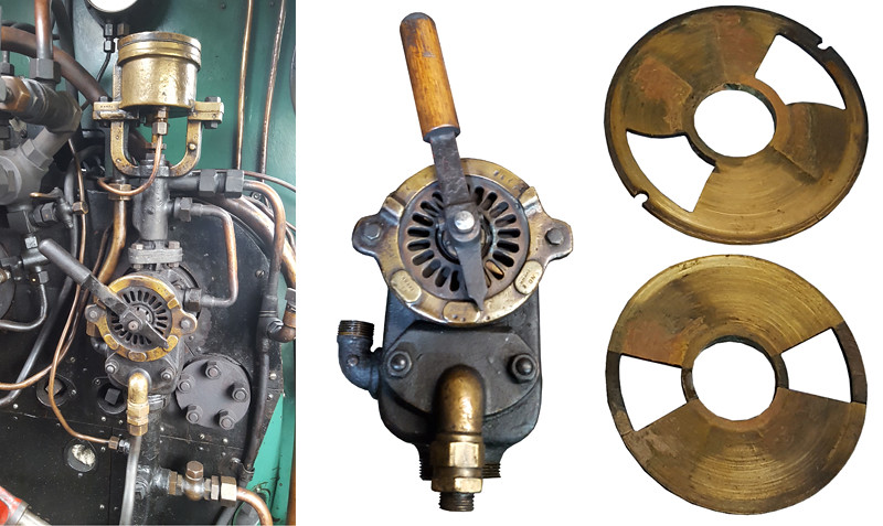
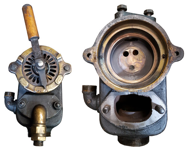
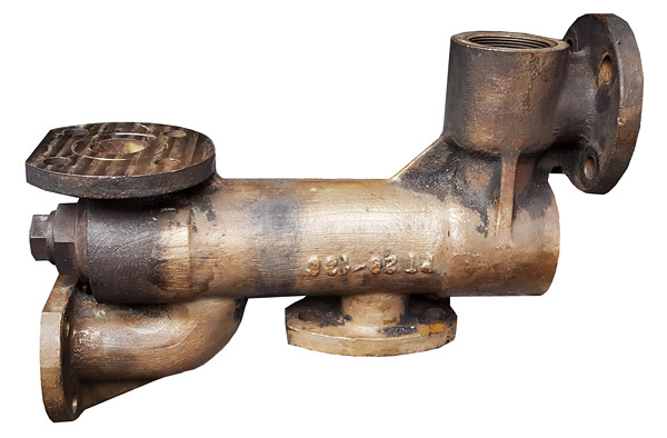
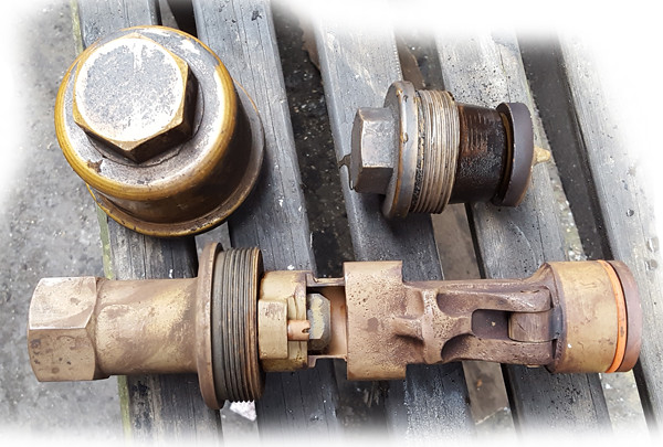
Go for it Adam! It's time we had a revolution! My only concern is that it might be one of weight. It may require a small spring to help keep it shut. The Terrier one is interesting and I am going to try and make an authentic one.  Injector 01 Injector 01 by Ed Cloutman, on Flickr  Injector 02 Injector 02 by Ed Cloutman, on Flickr |
|
|
|
Post by Cro on Apr 12, 2018 9:45:21 GMT
Ed I'm sure one day I'll reveal the secret....I hope to start in the next few days on the injector.
Looks like an interesting design, good luck with it.
Adam
|
|
|
|
Post by ivattlms on Apr 12, 2018 17:33:53 GMT
Hi Ed
My concern mill is a Myford VMC wish I had the VME which had a bigger table ,i use stepper motors on the table and the quill my control system runs in DOS as my cad/cam does as. well,when you see the shapes you can produce magic,best of luck
|
|
|
|
Post by terrier060 on Apr 13, 2018 8:53:32 GMT
We got a lot done on the boat yesterday despite the weather. Lagging is almost done and looks quite smart in the two colours. We should be able to fit the gauge glasses soon. 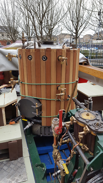 Boiler Lagging 02 Boiler Lagging 02 by Ed Cloutman, on Flickr |
|
|
|
Post by terrier060 on Apr 13, 2018 16:31:19 GMT
I really hope it works Adam - I love people who experiment and try out new things - and won't it be something if it works!
|
|
|
|
Post by terrier060 on Apr 13, 2018 16:43:40 GMT
Hi Ivattlms
I am really keen to have a go at CNC after seeing what Roger can achieve, but be is very experienced and I suspect I would not get anything like the quality he manages. Also I should have to give up valuable wokhshop time that I could spend on the Terriers. So I think I may sell all my telescope equipment and purchase a small CNC mill if such a thing exists. Small and solid - I am sure Roger will say the only way to get that is to make one yourself! HE is very clever.
|
|
uuu
Elder Statesman
 your message here...
Posts: 2,810
|
Post by uuu on Apr 13, 2018 17:50:28 GMT
I have an Emco PC mill 50, which is small, (if 150kg is small), and I like it. I did have to upgrade the electronics (Emco wanted £15000 to overhaul it, I only spent £1000).
It has a substantial cast iron chassis, ballscrews, a 3 phase spindle motor, and a nice BT30 toolholder system.
Wilf
|
|
|
|
Post by Roger on Apr 13, 2018 19:07:14 GMT
Hi Ivattlms I am really keen to have a go at CNC after seeing what Roger can achieve, but be is very experienced and I suspect I would not get anything like the quality he manages. Also I should have to give up valuable wokhshop time that I could spend on the Terriers. So I think I may sell all my telescope equipment and purchase a small CNC mill if such a thing exists. Small and solid - I am sure Roger will say the only way to get that is to make one yourself! HE is very clever. Hi Ed, You'll be surprised at how easy it is to get to grips with CNC since you already know how to use a manual machine. None of the fundamentals of cutting materials are changed, just the strategy that sometimes results in many more cuts than you would ever choose to do by hand. There's no reason why you can't get superb results that are easily as good as mine. Converting a machine is a pretty big job, but it's probably the only way to get a substantial machine for an affordable price. If you can live with a smaller machine and keep the manual mill then that's one solution. I think most people only imagine that CNC would be useful for those tricky jobs that require awkward geometry such as expansion links and such like. That misses the point in my opinion because CNC makes life easier on just about any job, regardless of how simple it is. This is why I think it makes more sense to make your main milling machine CNC rather than having a less capable smaller one that probably won't get used anywhere near as much as it otherwise would be. |
|
|
|
Post by terrier060 on Apr 28, 2018 19:01:28 GMT
I've got a bit side-tracked, what with the launch and now having a go at Fusion 360 in preparation for having a go at CNC. I have successfully completed a tutorial to get the basics and uploaded by 2D CAD mainframes drawing which went in OK once I got the units correct. Also had to close the spline on the frame edges to get a plane surface to extrude. Now will have to look at the CAM part. 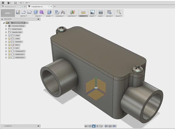 Fusion 002 Fusion 002 by Ed Cloutman, on Flickr 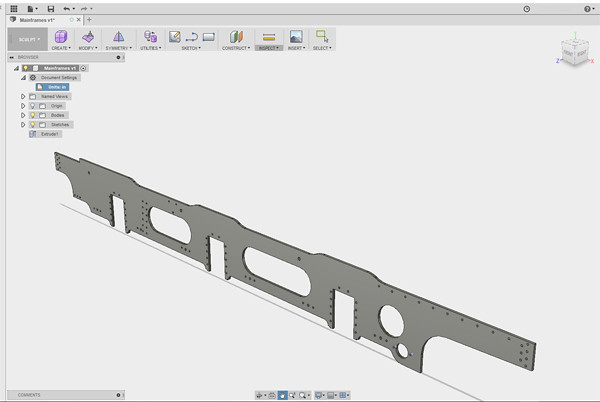 Fusion 001 Fusion 001 by Ed Cloutman, on Flickr |
|
|
|
Post by terrier060 on Apr 30, 2018 13:52:47 GMT
Thanks all of you. Roger is to blame - he does such great work so I felt I should have a go, but must try and get used to the software first. I want to produce the dome and chimney base. I have succeeded to draw the whole locomotive in Blender (which is great free software, by-the-way, if you want to animate in TrainSim (Railworks). Haven't a clue yet how to do it in Fusion 360. Am off to Thornbury now to give a talk to Thornbury Photographic Society (not on locos though)!
Ed
|
|
|
|
Post by terrier060 on May 2, 2018 10:05:53 GMT
Hi Roger - I got into my Flickr account thank goodness, but I hope you have read the thread on Flickr which is very worrying and might explain why I could not get into my account. Please, please Roger make sure all your photos and texts are safe somewhere. I am sure this applies to many of us who find them so enlightening and helpful. It would be a disaster if they were lost. This applies to everyone of course and is a real worry for such an important Forum. Anyway to continue my story I have managed to produce a chimney and dome base and should like to have your opinion. I have yet to get into the CAM part. 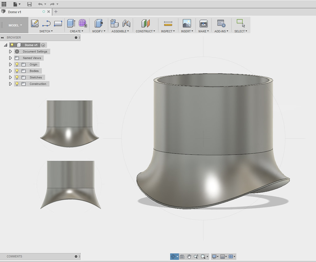 Terrier Dome Base Terrier Dome Base by Ed Cloutman, on Flickr 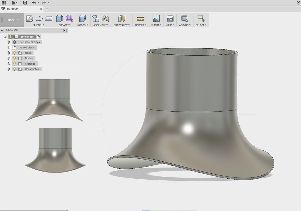 Terrier Chimney Base Terrier Chimney Base by Ed Cloutman, on Flickr |
|
|
|
Post by Roger on May 2, 2018 12:59:48 GMT
Hi Ed,
Can you tell us what method you used since there are several ways to go about this. What you've done certainly looks right. For shapes like this you can just model one quarter of it and then mirror the rest (if it will let you!). For a tapered boiler and a safety valve cover you would have to model at least half.
When you come to CAM this, there are several options. Doing it from the top as modelled can be problematical because of the vertical top piece. If you can just make the skirt and join in the cylindrical part then it's not a problem. The only issue with that method is that you then have to orientate and hold it to machine the underside. I'd machine a flat somewhere on the outside of the stock before removing it from the chuck so you can clock it true again.
Either way, you need some sort of mandrel to hold it for the second operation.
Of course you could machine the underside first, and that might actually be the easier way for holding it for the second operation. You'd need a curved fixture to do that though.
Alternatively, you could do what I did and machine it on its side, one half at a time which allows both the sides and the end to be machined without taking it out of the chuck. You can find the details of what I did in my thread if you want to do it that way. You would leave extra material on the parallel portion for finishing in the lathe.
One final note.... for any work done on its side using a rotary table, be sure to offer up the cutters you intend to use to make sure you have left enough overhang to miss the chuck!
|
|
|
|
Post by terrier060 on May 2, 2018 17:13:20 GMT
Hi Roger What I thought I would do is cut the curved base first, and the hole through the middle, though make the hole smaller diameter than the finished one for strength etc. Then mount it vertically on a stub mandrel to machine the outside. As you say I shall reduce the height to the start of the parallel part. Same with the chimney. I may not have done the shape of the curve very correctly - I just followed this link and did the same as they did. www.youtube.com/watch?v=9qE9yhgXfb4Ed |
|
|
|
Post by Roger on May 2, 2018 17:27:25 GMT
Hi Ed,
That's a lot easier than the method I used, but I'm not sure if the geometry is exactly right. The reason I say that is because it would appear that the middle part that defines the curve of the loft is a circle, and I'm not sure if it should be. I would have thought that it should be more like an ellipse? The result certainly looks good though, so either I'm mistaken or it's close enough that it doesn't matter.
Just to clarify my thoughts on this.... if you look at the GWR Works Drawing for the chimney, you can see that there's a minimum and maximum radius of blend. The minimum radius is obviously on the boiler centre line at the top and the maximum is at 90 degrees to that. Since those two radii start at the same place on a diameter, it stands to reason that at any point below that, a horizontal cross section won't describe a circle.
So my thinking is that you need to look at those two radii and find the two lengths of the axis of an ellipse for whatever height you decide on for that section and use that instead of a circle.
I don't think my package is as sophisticated as Fusion360, but maybe it's possible to do it that way.
That will certainly work for machining the part. I ended up attaching the petticoat pipe to the chimney for the tapered bore from end to end.
|
|