|
|
Post by Roger on Dec 30, 2017 11:18:45 GMT
I'm afraid the photos are blocked, all I can see is a black and white 'no entry' sign
|
|
|
|
Post by Roger on Dec 30, 2017 12:31:33 GMT
Thanks Roger, sounds like senior moment on my part (didn't set sharing options correctly). Should be fine now. If not I will post pictures differently. I'm afraid that doesn't work. It looks different, there's a generic thumbnail, but no picture. Maybe there are some clues in the sticky thread that might help with whatever hosting program you're using to store your photos. I don't think there's a way to point this Forum to a picture hosted on your computer or to Dropbox, they have to exist in a public library space such as Flickr. |
|
jma1009
Elder Statesman

Posts: 5,901
|
Post by jma1009 on Dec 30, 2017 13:41:56 GMT
Hi Chris,
Quick answer - No.
It would help if you showed the arrangement of Walschaerts you have arrived at and the lifting arrangement of the radius rod.
If the 'envelope' is compromised in some way then some bizarre results arise that are tricky if not impossible to resolve.
Cheers,
Julian
|
|
|
|
Post by Roger on Dec 30, 2017 16:55:02 GMT
Hi Chris,
I can see the two screen shots of the dialog boxes from the program, but that's all.
|
|
|
|
Post by bambuko on Dec 30, 2017 17:21:48 GMT
Thank you Roger and sorry for all this nonsense. Let's have another go: Using W. B. Hall's "An approximate, but logical, method of designing valve gear", followed by D. L. Ashton's "Design Procedures for Valve Gear" I have come up with a design for Walschaerts gear. Seems OK to me , but... not perfect. Tried tweaking various parameters to see if I could get it better, but all I have tried seemed to make things worse, hence my question here. Do the graphs below look reasonable to you guys? 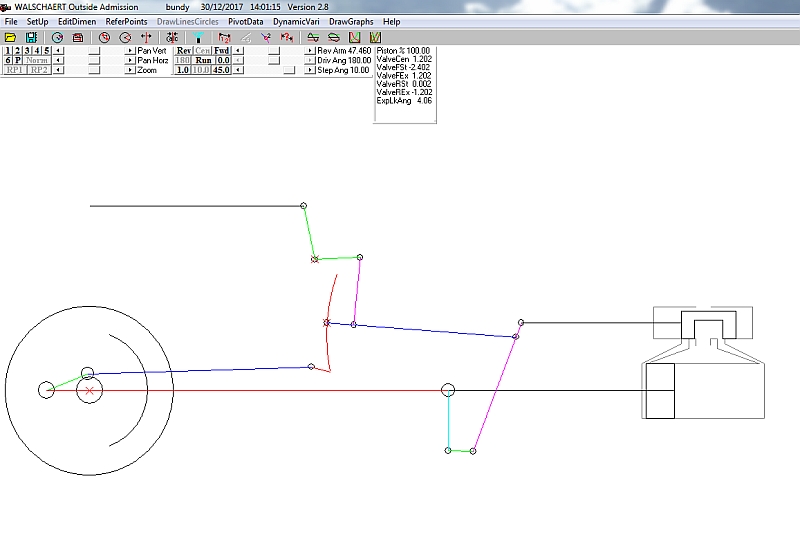 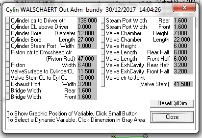 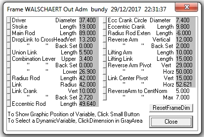 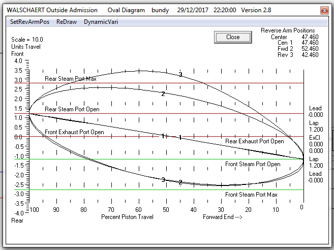 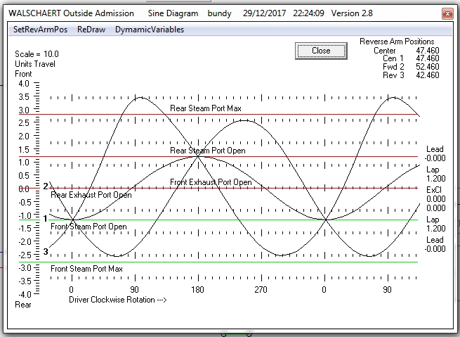 |
|
|
|
Post by Roger on Dec 30, 2017 17:27:51 GMT
Hi Chris,
That's five things in all now, so hopefully that's enough for a judgement to be made. Sadly I'm not qualified to comment!
|
|
|
|
Post by bambuko on Dec 30, 2017 18:00:10 GMT
You helped anyway :-)
I am not having a good day with inserting of photos...
As Julian has said - the results are NBG (or "bizarre" :-) , even if a lot better than what I have started with...)
I've got few ideas I am playing with at the moment - good fun.
|
|
|
|
Post by Roger on Dec 30, 2017 18:23:18 GMT
Hi Chris, The only other thing I can suggest is that you print out the indicator diagrams of the type shown here in my Wiki for SPEEDY
Although I can't say how Don arrived at the final arrangement, you can see why it's better than any of the previous designs. Hopefully the descriptions I put in the text there explain what's going on and what's required. |
|
|
|
Post by andyhigham on Dec 30, 2017 20:16:37 GMT
Forwards doesn't look too bad
|
|
|
|
Post by bambuko on Dec 30, 2017 20:43:20 GMT
Yes, forward looks OK (at least to me...).
It's the reverse that's a bit wonky :-)
|
|
|
|
Post by Roger on Dec 30, 2017 21:13:19 GMT
Are these diagrams only showing the situation in full gear?
|
|
|
|
Post by bambuko on Dec 30, 2017 21:52:18 GMT
As I go towards mid-gear things look better (at least to my un-trained eye): 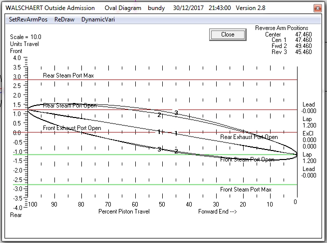 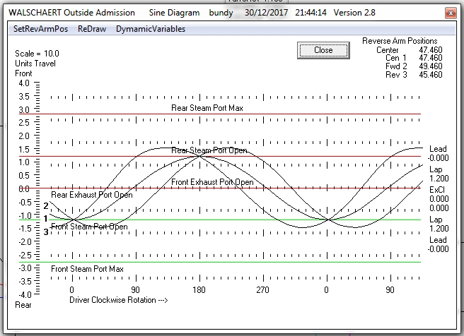 so it seems that something I have introduced into the geometry distorts the events at extremes (i.e. FG) I am trying few things at the moment... |
|
|
|
Post by Roger on Dec 30, 2017 22:12:50 GMT
Can you get a family of Indicator Diagrams like I show in my Wiki? To my untrained eye they seem to paint a much clearer picture of what's going on in the cylinder, which, after all, is surely all that matters?
|
|
|
|
Post by andyhigham on Dec 30, 2017 23:45:50 GMT
How much time will you spend hauling a train tender first?
|
|
jma1009
Elder Statesman
Posts: 5,901
|
Post by jma1009 on Dec 31, 2017 0:42:00 GMT
Hi Andy,
An important question allied to the size of Chris's design which would appear to tie in nicely with his interest in smaller gauges such as Gauge 1, and perhaps also radio control?
With lower steam pressures and lack of superheating (I presume) with say Gauge 1, expansive working when 'notched up' becomes impracticable due to condensation. Good valve events are still very important for efficiency, but not over the range of cut offs we would expect on a superheated 3.5"g or 5"g loco at 90 psi working pressure.
I have a few further thoughts on the further diagrams Chris has supplied but want to double check a few things as I have not done a Hall Walschaerts simulation for quite a few years and cannot remember how the backset for the expansion link tail is arrived at on Hall simulator.
Cheers,
Julian
|
|
|
|
Post by bambuko on Dec 31, 2017 10:41:10 GMT
Hi Andy,
Actually the reason I am fussing about it, is exactly because I expect similar time in forward and reverse.
It's not for running in circles but for shunting :-)
See an example (not mine) here:
Yes, it is RC steam.
As Julian says, notching up is not that important, pressure is lower and the steam is wetter (although dryed), nevertheless valve events should be correct (or at least as good as can be) in both directions. If it was only for forward running at express speeds, the design would be much simpler indeed.
ps I think I have found one of my mistakes - and it is the position of expansion link pivot point (more to follow)
|
|
pault
Elder Statesman
Posts: 1,496
|
Post by pault on Dec 31, 2017 13:00:44 GMT
Hi
A couple of things, could you post pictures of the valve gear mid travel and front dead centre?
Also, I used a simulator to check my design of a Walschaerts derived valve gear and got rather hung up trying to get the diagrams perfect. After a large amount of time I looked at the tabulated valve travel and found that the changes I was making to the valve gear were only resulting in changes to the valve travel of 0.0001” to 0.0002” so not worth worrying about. That said back gear on the diagrams does seem to be quite bad.
How did you arrive at the back set and eccentric rod lengths?
|
|
|
|
Post by bambuko on Dec 31, 2017 13:27:53 GMT
... could you post pictures of the valve gear mid travel and front dead centre? ... 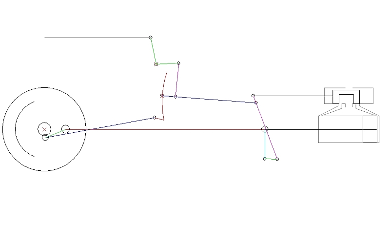 got rather hung up trying to get the diagrams perfect... Hence me bouncing it off you guys, so that I don't end up chasing my tail :-) ...How did you arrive at the back set and eccentric rod lengths? Followed Don's advice (page 6 and 7) using CAD. I think (as per p.s. in my last message) I got things wrong with placing of the expansion link pivot) - I am redrawing things as we speak to put it into simulator, be back soon... |
|
|
|
Post by joanlluch on Dec 31, 2017 15:56:35 GMT
Hi Bambuko, I designed the valve gear geometry for my freelance locomotive from the ground up, which means that it was not based on the improvement of any previous existing design. I used the Allan Wallace simulator. I chose a Baker type, not walschaerts, but the design steps are virtually the same. I found the simulator to be an excellent tool to validate your design, and it may help to improve a couple of aspects, but you must start with some clear geometry concepts that you must keep invariable through the simulation stage. Time ago I posted a brief description of the procedure that I followed, but I will try to expand it further now. See the page below, down about the middle of the scrolling area: modeleng.proboards.com/thread/10937/freelance-pacific-loco-lsfornells-build?page=2I used essentially a graphic approach, rather than math formulas, to determine the correct size and position of several elements. The procedure to design a valve gear is iterative, but you must iterate through ALL the steps every time you make a change. I.e, you can not change something in one step without going through all the remaining steps. (1) Start by choosing a port width and a valve lap that suits your locomotive size. I chose a valve lap that is 1/2 of the port width. This determines the geometry of the steam valve: Port width + Lap = Valve Width. I used 3 dimension units for the Valve Width, 2 for the Port Width, and 1 for the Valve Lap. In my case, the Valve Width is 7.5 mm, Port Width is 5 mm, and Valve Lap is 2.5 mm, which follow the said 3,2,1 dimension proportions. This choice of proportions and sizes does not affect the events of the valve gear because this is determined by the next steps, but they affect the sizes of the remaining elements. (2) Choose a radius for the return crank circle, a size for the expansion link, and a tailpin distance from the expansion link centre, that would give you the desired valve travel. This may be changed on a further iteration in order to select the right cutoff value at full gear, which should be 75% or slightly above for a smooth locomotive start. (3) Find the combination lever sizes. I used a geometrical approach. Draw a right triangle with half the stroke at its base, and the vertical distance between piston axle and valve as height. Trim or extend -depending if it's outside or inside admission- the base by the lap+lead distance and trim or extend the side of the previous triangle accordingly. For a miniature locomotive, the lead can be set always to zero, so in practice you only use the lap for this. The sides of the two triangles give the proportions of the combination lever. You can also use the formulas in the Don Ashton book to get the same exact result. However, note that the important data is the /proportion/. You can set the actual size slightly shorter -while maintaining proportions- in order to get the union link parallel to the track on half piston travel. Most locomotives are like this. (4) Draw a sketch of the locomotive with the valve at its centre position and the connecting rod big end at the most lower location, i.e driving wheel at 90 degrees with respect to the end of piston travel. Note that the location of the cross head with the wheel at 90 degrees does NOT exactly correspond to half piston travel, as the connection rod angle makes it appear slightly shorter. You can chose to keep the combination lever vertical in this scenario, but then it will have different inclination angles at each ends of piston travel. Or you can account for the apparent "shortness" of the connection rod, and set the combination lever slightly inclined in order to get the same angle at both piston travel ends. I found that the later approach gives more equalised valve events. Whatever approach you chose, this will allow you to determine the radius rod length and expansion link radius (same as the radius rod length). (5) Using the same drawing, you can determine the angle and length of the return crank as well as the optimal back set and length of the eccentric rod. Just draw a line from the bottom of the expansion link (tail pin) and the centre of the driving wheel. The intersection point at the return crank circle determines both the length and angle of the return crank. It also determines the length of the eccentric rod. The backset must be determined at the same time. Backset is crucial because it gives equal angles of swing for the expansion link when the wheels are at 90 or -90 degrees. On the line from the tailpin to the centre of the driving wheel, mark the relative ends of a supposed eccentric rod at 0, 90 and 180 driving wheel degrees. Mark the points in such a way that the angles between these points and the centre of the expansion link are equal at both ends. Try several times, the greater the backset the greater the swing angle at the 0 degrees and the smaller at 180 degrees. Find the optimal backset to have these angles equal. At that point you will also have the correct angle and length of the return crank and the length of the eccentric rod (6) Now it is time to begin simulating the gear. If all the above has been done correctly, chances are that the gear is already very good without further changes. The most important to have equal valve events on forward and reverse is the correct backset setting. Always remember that you should not change anything on the simulator without following again all the steps above. For example, backset, return crank and eccentric rod are all interrelated, you can not just change one without affecting the others. However, the simulator will allow you to actually see the valve events and decide whether you want to add some lead, or to adjust the cut-off figures. The later requires start over from step 2 because all the remaining parameters will break. The above is in any case my approach and what I did to design the gear of my locomotive. It may be rather tedious, but it gave excellent results in my case. I spent many days (possibly weeks) before I was able to grasp it all to an acceptable extent. |
|
|
|
Post by bambuko on Dec 31, 2017 19:20:54 GMT
Thank you joanlluch! It is always very interesting to see how others have solved the problem. Your approach seems similar. The main difference is that both you and Roger (and everybody else it seems) prefer Wallace simulator. I find Dockstader easier, perhaps because I am familiar with it more than with others. I have revised my design in the light of the discussion on this thread and now it looks as follows: 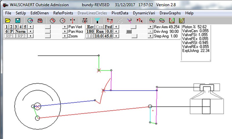 Cylinder dimensions: 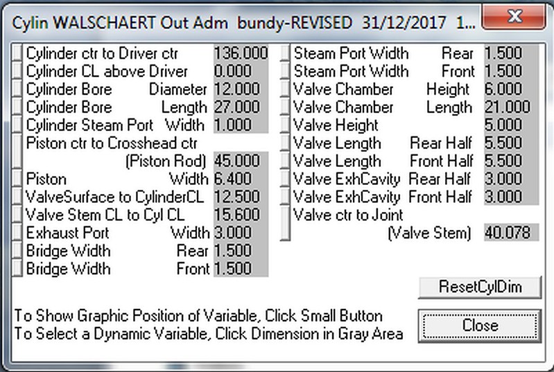 Frame dimensions: 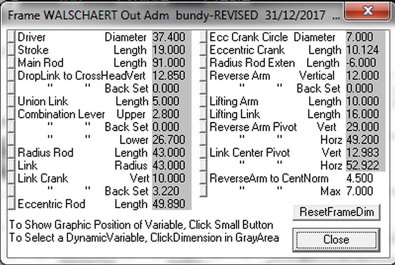 The results are as follows: 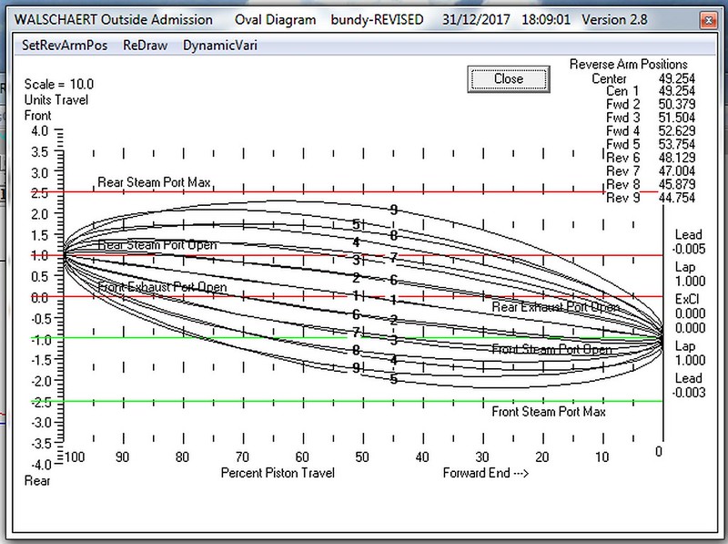 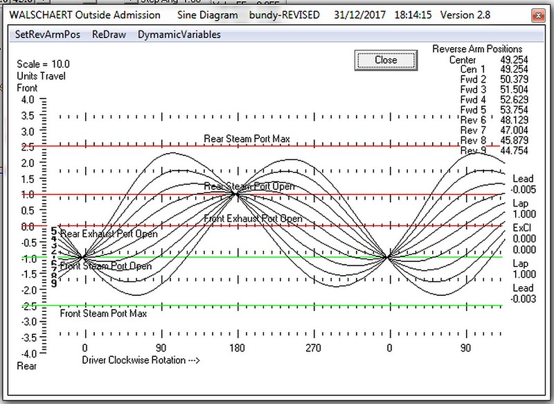 Forward port opening: 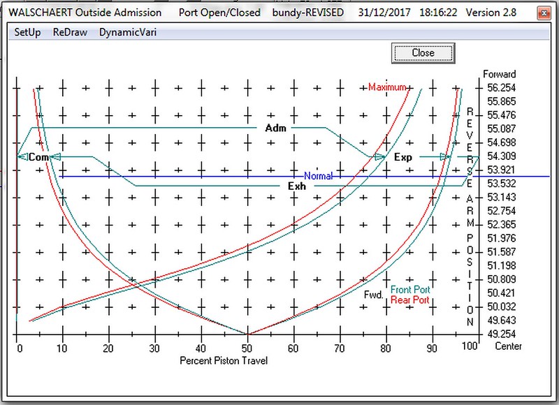 Reverse port opening: 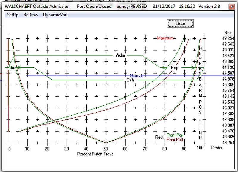 and finally steam diagram: 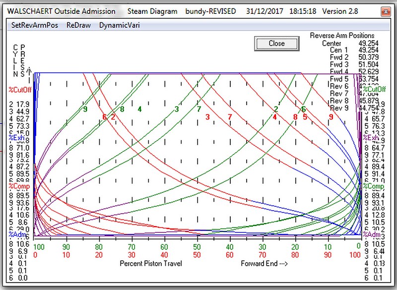 It seems (to me at least) reasonably satisfactory? and a lot better than my first posting in this thread? Happy New Year to you all! |
|


