JonL
Elder Statesman
 WWSME (Wiltshire)
Posts: 2,909
|
Post by JonL on Feb 14, 2019 19:18:03 GMT
It's certainly the case at our club, rigid bars between everything. I think its to avoid punters putting their fingers where there is a trap risk. The wheels are shielded by the seats.
|
|
barlowworks
Statesman
 Now finished my other projects, Britannia here I come
Posts: 874 
|
Post by barlowworks on Feb 14, 2019 19:26:10 GMT
Yes it's the case at the Sheffield club also, on the ground level and the raised track. Also solid links between the loco and the club owned driving cars.
Mike
|
|
stevep
Elder Statesman
Posts: 1,070
|
Post by stevep on Feb 14, 2019 19:39:11 GMT
There should only be a sideways action on over-run if the couplings are not at the correct height and centreline.
Before I made the multi-gauge coupling, I used a long bar to connect my Rob Roy (3 1/2" gauge) to my driving trolley (5"), and on the over-run, it did, indeed, make the engine 'crab' on the track.
|
|
|
|
Post by delaplume on Feb 14, 2019 19:39:24 GMT
Kinver have an override system on the carriages------each carriage couples to the next via overlapping triangular plates and a vertical pin...
A few years ago a small 7.25" gauge 0-4-0T loco's rear wheel set was de-railed by over-run at Wolverhampton........Not a regular thing but it can happen non the less..
Concertina rubber covers are recommended between carriages to prevent childrens fingers being trapped...
|
|
|
|
Post by andyhigham on Feb 14, 2019 20:03:27 GMT
At RVLS the couplings between carriages are solid bars. The connection is spring loaded in compression and applies the carriage brakes on overrun (similar to a caravan)
|
|
uuu
Elder Statesman
your message here...
Posts: 2,812
|
Post by uuu on Feb 14, 2019 20:15:57 GMT
Where the loco is 040 or 060 with an over hang at the back, and the driver is on a bogie wagon, you get quite a difference in the sideways displacement of the coupling on corners curves, so this is not the place to test the loco brakes. Not that you'd be using the loco brakes - you'd use the train brakes - but electric locos can generate quite a bit of retardation during re-gen, and the Eaton transmission locos can deliver quite a bit of engine braking.
Wilf
PS - Roger - please say stop if you want to kill off this topic on your thread.
|
|
JonL
Elder Statesman
WWSME (Wiltshire)
Posts: 2,909
|
Post by JonL on Feb 14, 2019 20:22:53 GMT
At RVLS the couplings between carriages are solid bars. The connection is spring loaded in compression and applies the carriage brakes on overrun (similar to a caravan) Funny you mention that, I was just thinking that would be a good idea for mine should I make one. |
|
|
|
Post by Roger on Feb 14, 2019 22:07:03 GMT
By all means carry of discussing this interesting topic, it's not something I've seen debated at length before.
|
|
jma1009
Elder Statesman
Posts: 5,901
|
Post by jma1009 on Feb 14, 2019 23:16:03 GMT
Couplings...
I had some considerable involvement with the Southern Fed and HSE after the accident on the NRM miniature 7.25"g track in the late 1990s that led to the HSE publishing an HMSO book detailing all sorts of aspects of passenger hauling miniature railways in 3.5", 5", and 7.25"g. (At the time I had just finished a big legal case involving the HSE as a 3rd party, and starting a case against them to the Court of Appeal - I had excellent links with HSE Inspectors and their legal team as a result!)
The only runaway loco I ever witnessed was Don Young driving the Steve Titley/Harry Lumb 5"g Railmotor No.3 on the IWMES track at Broadfields, and the reason for this should have been noticed at the time by those in charge (I was then a teenager).
The IWMES raised track had 6 excellently made passenger cars with proper 3 link couplings and proper sprung buffers.
It was not unknown to get to another club's track pre-the late 1990's to find that the 3 link chains they used would not fit over a loco rear drawhook, so I still have a number of thin welded steel 3 link chains in my running box that date from this time. They could also fit between clevis drawbar fittings.
More alarmingly, to someone used to what I considered to be the excellent passenger cars/trolleys of the IWMES, I was surprised to find that most other clubs did not fit sprung buffers to their passenger cars due to sheer expediency and avoiding the extra work involved in making the buffer fittings. Solid drawbars were therefore required.
Jumping ahead again to the HSE book published around 1999, we followed the HSE guidelines as part of a properly carried out 'risk assessment'. Shrouds were fitted over the gap between 2 passenger trolleys so that kids could not get their fingers caught between the buffers or fiddling with the 3 link couplings when not 'taught'. A trial was made with solid drawbars on the passenger trolleys. We never considered it necessary to require solid drawbars on the IWMES equipment between loco and first passenger trolley. All this was in the context of very heavy fare paying passenger usage primarily at portable track events rather than Broadfields, the club track.
When you visit another club track which has no proper sprung buffers on the passenger trolleys, a solid drawbar link between loco/loco tender is preferable.
Cheers,
Julian
|
|
Gary L
Elder Statesman
Posts: 1,208
|
Post by Gary L on Feb 15, 2019 0:21:04 GMT
FWIW... I like to think in terms of the critical link between loco and driver. If the driver is sitting on the tender, then a solid link between the two. If the driver is on the loco itself, nothing special needed. If the driver is on a carriage behind, as with Speedy and most raised-track trains, then a solid link connecting the two. It hardly matters if the driver's vehicle is then connected to the train behind with a bent safety-pin; the risks attending a breakage there are low. But a breakage between the loco and its controlling intelligence (?) could be extremely serious, as has been pointed out, and is eminently foreseeable, even if the likelihood (or experience) of it happening is not great. -Gary Hi Gary, I'm inclined to think that the solid coupling is an over reaction to incidents caused by poorly designed or weak couplings. I can see where they're coming from, it's easy to inspect and nobody gets their nose put out of joint by a subjective opinion about whether their coupling is man enough. In reality, there's no way a three link chain is going to jump off a deep hook, it's never going to happen. That could easily have been stipulated as the method except it still has the issue of needing to know that the hook isn't held on with gaffer tape. I just think it's a shame that we're stuck with a ghastly system that looks awful when a well designed hook is perfectly satisfactory. I don't have a problem with a safety chain if that's what it required to satisfy the Health and Safety people though. While that is undoubtedly true of your immaculate work Roger, we ought to spare a thought for club committees that have to make rules to cope with all levels of workmanship (and idiocy)! Logically, there is only one safe way to go with chains of any kind, and that is to proof-test them regularly and issue a certificate; as happens with lifting gear and ships' equipment without any argument. A scale screw-link coupling is a chain after all, and coupling a loco to its driver is a safety-critical application. Do I hear any takers? It is true that a driver alone is not much of a load, but start adding a trainload of passengers, and shock loadings on pick-up which are a feature of loose couplings, and you have an 'incident' waiting to happen sooner or later. Personally I'm happy with a bar link, even if club rules didn't mandate it... -Gary |
|
|
|
Post by Roger on Feb 16, 2019 13:06:58 GMT
Although I haven't finished the design of the cab floor, I know enough to make a start of preparing the base. This is going to be done in the same way as the Bunker, ie using a thick plate machined to leave a thin edge and raised portion for riveting the sides and front on. I had made a start on this before, but the plate was too thin and bent to be usable. This time I've started with 8mm plate to make certain I can clean it up on both sides and get it flat before clearing out the bulk of the material. The Steel is hot rolled plate which happens to be pretty flat, but I'm going to normalise it to make sure it stays put. Here I've supported the plate on a couple of scraps of tile and made a through oven in an attempt to keep in as much heat as possible. 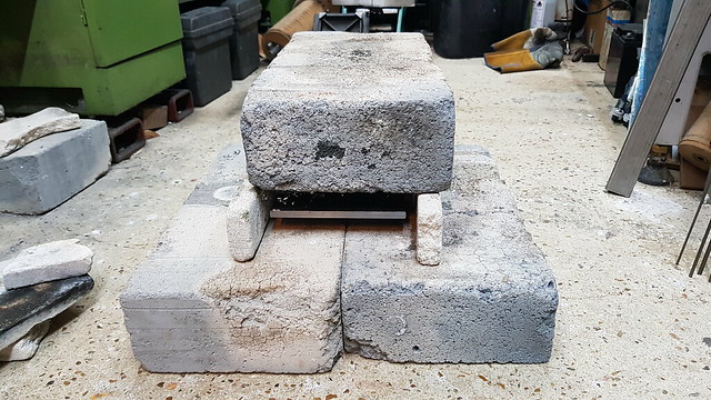 20190215_114631 20190215_114631 by Anne Froud, on Flickr I managed to get the front half bright red and the back duller, so I took off the top, gave it one last blast with the torch all over and then dropped it all flat to keep the heat in. I pushed some pieces of tile up to the edges to insulate the sides too as much as possible. 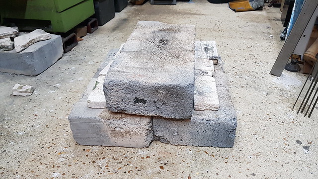 20190215_115527 20190215_115527 by Anne Froud, on Flickr It was still pretty flat, so I cleanup up the edges with a file all round and found that it sat down without rocking better one way, so that's how it is here. This is my Fine Pole magnetic chuck that I usually use on the grinder, but I thought it was worth a try to see if it would hold this well enough to skim the plate. I heaved on it and it didn't budge, so I decided to give it a go. 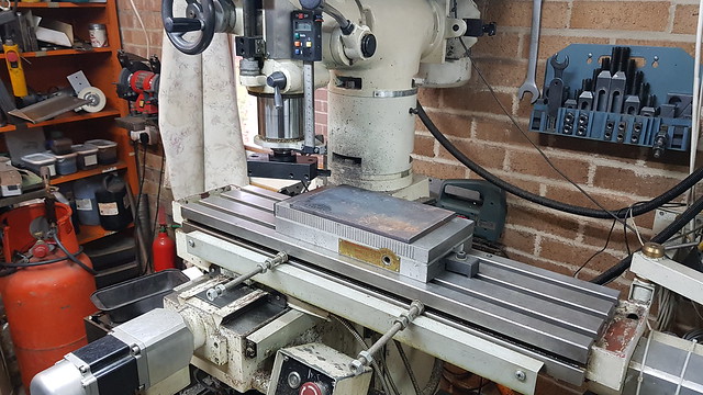 20190216_095641 20190216_095641 by Anne Froud, on Flickr 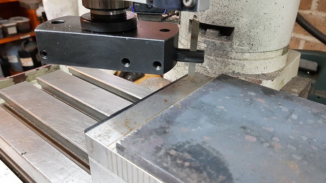 20190216_095657 20190216_095657 by Anne Froud, on Flickr Here's a wobbly video to give some idea of the feed and speed. This is taking a 0.2mm deep cut to make sure it's getting under the skin... 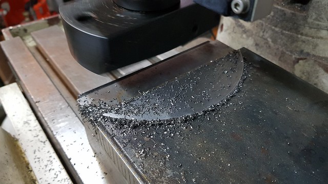 20190216_101557 20190216_101557 by Anne Froud, on Flickr ... which worked out rather well. I just smeared cutting oil over the whole thing and let it get on with it.  20190216_124225 20190216_124225 by Anne Froud, on Flickr |
|
|
|
Post by danlank on Feb 16, 2019 14:29:21 GMT
Just a simple input, at Beech Hurst we use standard hooks as Roger has beautifully made and 3 link chain and we pull 4-6 car loads on just that and never has the club known an issue (not that I've ever heard of at least and I imagine if there had been we would be doing something different!). Adam FWIW... I like to think in terms of the critical link between loco and driver. If the driver is sitting on the tender, then a solid link between the two. If the driver is on the loco itself, nothing special needed. If the driver is on a carriage behind, as with Speedy and most raised-track trains, then a solid link connecting the two. It hardly matters if the driver's vehicle is then connected to the train behind with a bent safety-pin; the risks attending a breakage there are low. But a breakage between the loco and its controlling intelligence (?) could be extremely serious, as has been pointed out, and is eminently foreseeable, even if the likelihood (or experience) of it happening is not great. -Gary I’m not sure I agree that the driving car and train coupling is less important - if something were to happen going uphill then there’s the risk of the whole train running away backwards. In that case, wouldn’t it better to have the driver with the train and driving car brakes to bring it under control? (Assuming the train itself is unbraked as per my old club...) I never saw a breakaway, but I know that there was one at the club I grew up in, a Doris broke its chain (could have been the tender drawbar), another member caught it going past the steaming bays but managed to pull it off the track and break their elbow into the bargain. I believe the club changed to solid bar couplings universally after that... |
|
stevep
Elder Statesman
Posts: 1,070
|
Post by stevep on Feb 16, 2019 16:53:52 GMT
Our club rules (Tiverton) require that when there are more than two passenger vehicles (driver's trolley and one more, or two passenger trollies) we have a guard on the rear trolley, with a brake. So in the event of a train coupling failing (which we hopefully wouldn't have, as we used solid bar couplings), the guard can apply the brakes.
He can also monitor the behaviour of any passengers, to avoid them standing up, or larking around.
That all said, we own our own land, and do not have public running, so it's not too much of an issue.
|
|
|
|
Post by yorkshireman on Feb 16, 2019 17:24:28 GMT
Hallo All
I have seen it with my own eyes on a club track:
When a coupling bar between loco an train breaks or comes loose, a loco under full steam can dart away before
the driver might take any action. This is why I have now a thin steel cable in addition to a bar between between
loco and driver's car.
In the particular case the loco raced away, through the station, where luckily nobody was close to the rails.
The loco then went off the track and landed on its side - considerable damage...
Nobody was hurt... I was NOT the driver and I will not give any further comment, OK?
-Johannes-
|
|
|
|
Post by Roger on Feb 16, 2019 21:54:53 GMT
I need to figure out how to control the bypass valve, and that looks like it's going to have to be a third lever on the LH side of the cab where these two water valves come out. That means I need to know exactly where these are going to go, and modelling these valves will make that possible. I don't have any works drawings for these, but I do know the diameter and thickness of the flanges from the Side Tank drawing. 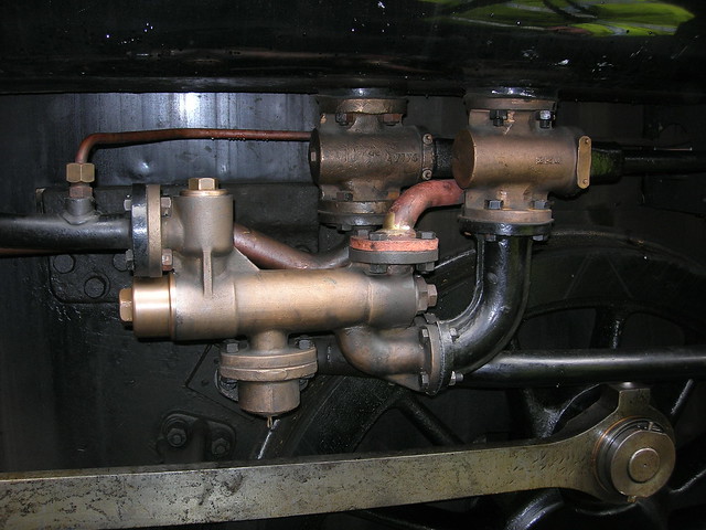 DSCN5687 DSCN5687 by Anne Froud, on Flickr This is my initial attempt, but it might need to be a little longer in the body to look right. 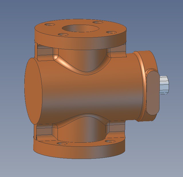 Injector water valve front Injector water valve front by Anne Froud, on Flickr I don't know if this extra boss on the back is there in fill size, but it's pretty well hidden and it allows me to put a clamp bolt in there to retain the gland section. 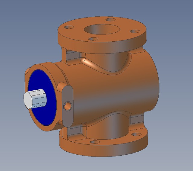 Injector water valve rear Injector water valve rear by Anne Froud, on Flickr This is how the inside looks. The valve barrel has a shallow hex pocket in the end to turn it. The hex on the shaft doubles up as a retainer for the 'O' ring and stops the shaft pulling out. There's an 'O' ring on the shaft and the OD for the seals. The bore is 5mm which is hopefully large enough. 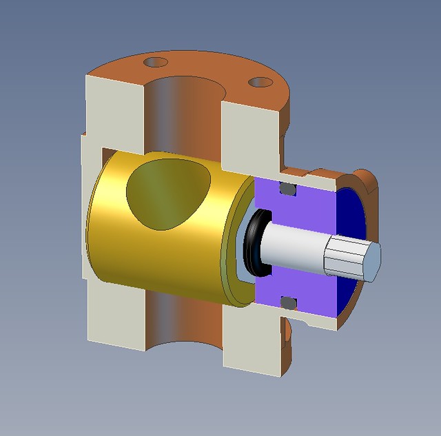 Injector water valve Injector water valve by Anne Froud, on Flickr |
|
|
|
Post by delaplume on Feb 17, 2019 19:18:14 GMT
I need to figure out how to control the bypass valve, and that looks like it's going to have to be a third lever on the LH side of the cab where these two water valves come out. That means I need to know exactly where these are going to go, and modelling these valves will make that possible. I don't have any works drawings for these, but I do know the diameter and thickness of the flanges from the Side Tank drawing. DSCN5687 by Anne Froud, on Flickr This is my initial attempt, but it might need to be a little longer in the body to look right. Injector water valve front by Anne Froud, on Flickr I don't know if this extra boss on the back is there in fill size, but it's pretty well hidden and it allows me to put a clamp bolt in there to retain the gland section. Injector water valve rear by Anne Froud, on Flickr This is how the inside looks. The valve barrel has a shallow hex pocket in the end to turn it. The hex on the shaft doubles up as a retainer for the 'O' ring and stops the shaft pulling out. There's an 'O' ring on the shaft and the OD for the seals. The bore is 5mm which is hopefully large enough. Injector water valve by Anne Froud, on Flickr Hi Roger, I might be able to help you here a bit........... I machined quite a few new / re-conditioned ones when working as a self-employed Contractor on the SVR at Bridgnorth machine shops.... As far as I'm aware by the 1930's onwards the GWR had 2 injectors available}---- the 8X and the 10X.........both shared the same main body and varied the outputs by different cones etc....and were thus stamped accordingly. This means that the attached water valves were of one design and could be seen on loco tenders......However these were fitted rotated at 90 degrees anti-clock to those in your photos....ie the R/H as seen would be at the top.... The emerging spigot that's part of the inner valve plug was a tapered square and in your photo you can just make out the shaped end of the control shaft ( in black ) where it sits over the emerging spigot.... Also, just below the top of the valve body, on that cast-in flat face, you can see what looks like 2 small circles ??-------These are the bolts that secure the top plate that holds down the plug.. On the delivery outlet pipe of that injector is a smaller pipe attached by flange and leading off to the R]H side---------that goes to feed the Pet Cock on the inside of the L/H cabside and gives the water supply to the slacking pipe...........This means you can only use the slacking pipe when that particular injector is working.... I've tried to find some photos of the water valve dismantled but no luck yet...........Yours is about right except the plug was tapered.. I hope that's of some help ?? Alan |
|
|
|
Post by Roger on Feb 17, 2019 19:46:12 GMT
Hi Alan, That sounds about right. I've got the Works Drawings of the injector and non-return outlet valve which is what the body is taken from. There are variations between the two injectors fitted on 1501 at the moment and also to the Works Drawings. I'm not going to stress about that, I expect it would look different again if I looked at it again in a year or two. The model below has gone through many iterations to get the proportions to look more like the real thing. I've also added an M8 x 0.75 (fine) threaded attachment with an O-ring instead of the four M1.4 bolts which are not really practical. The question is, should I put a short extension to the inlet and fit a Brass gauze finger as a filter? 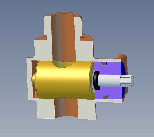 Injector water valve Injector water valve by Anne Froud, on Flickr The inside looks like this, with a pretty shallow bush that will be made from Phosphor Bronze since they're thin. Those will be Silver Soldered in place. I've moved them slightly further apart than the Works Drawings show so that I can unscrew them. The peculiar elbow will be machined in two halves and Silver Soldered together. 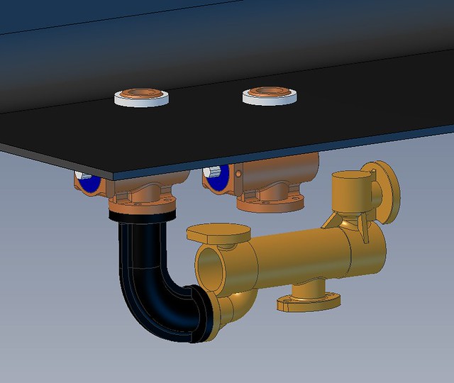 Injector water inside arrangement Injector water inside arrangement by Anne Froud, on Flickr So this is the overall look on the model...  Side view Side view by Anne Froud, on Flickr ... and this is how it looks on 1501. 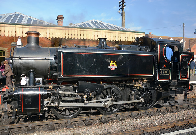 37567973140_c3be406d44_o 37567973140_c3be406d44_o by Anne Froud, on Flickr |
|
|
|
Post by David on Feb 17, 2019 22:33:49 GMT
That pipework is going to look good and I'm looking forward to seeing how you make the water valves. I've never seen a close to scale representation of the water valves etc except on the photos of Don's 9F.
You know we're going to be disappointed if you don't put that extra pipe on the outlet of the injector and have a working hose in the cab, right?
|
|
dscott
Elder Statesman
Posts: 2,438
|
Post by dscott on Feb 17, 2019 23:55:03 GMT
What I have done in the past for tank water filters is cut a screwed flange with a tube that has a long slice through it.
This has the mesh soldered to it and another bush fitted into the tank.
If it gets clogged it is an easy unscrew clean and put back possibly in the Steaming Bays!!!
The longer the slice the more mesh for filtering muck!!
David and Lily. One and a half frames now drilled! 1/16" drill broke after 300 holes... Bluntness suspected!
|
|
Gary L
Elder Statesman
Posts: 1,208
|
Post by Gary L on Feb 18, 2019 1:20:59 GMT
Hi Alan, That sounds about right. I've got the Works Drawings of the injector and non-return outlet valve which is what the body is taken from. There are variations between the two injectors fitted on 1501 at the moment and also to the Works Drawings. I'm not going to stress about that, I expect it would look different again if I looked at it again in a year or two. The model below has gone through many iterations to get the proportions to look more like the real thing. I've also added an M8 x 0.75 (fine) threaded attachment with an O-ring instead of the four M1.4 bolts which are not really practical. The question is, should I put a short extension to the inlet and fit a Brass gauze finger as a filter? [Snip] Now that will be a very intricate exercise in CNC machining unless that nice Mr Cro felt like making some lost wax castings of them for us less clever blokes? Every GWR engine needs a pair, although perhaps only easily visible on pannier tanks... A filter is definitely needed, and the gauze finger sounds a neat way of doing it. You shouldn't need to be too concerned about having to unblock them in the pits though; if your water is so filthy as to clog them, you will have your work cut out cleaning the tanks anyway. They are very like marine seacocks when seen in your sectioned view, and those too are always tapered, but using PTFE and a lot of care your parallel plugs will be more straightforward to manufacture- proprietary model tender water cocks are made that way, and without the benefit of the O-rings in your drawing. Looking forward to developments! -Gary |
|


