|
|
Post by Roger on Feb 24, 2019 22:55:08 GMT
Time to set the bodies up again for the final operations on the mill...  20190224_111521 20190224_111521 by Anne Froud, on Flickr ... facing off the outlet flange with a 16mm cutter taking just 50 microns off...  20190224_120840 20190224_120840 by Anne Froud, on Flickr ... drilling and reaming the cross hole to 5mm and adding the M1.4 flange holes. On the outlet side, I've decided to thread the flanges and add nuts to studs so they're left attached to the valve rather than have them loose. It's bad enough having bolts that small without having to mess about with a spanner on the top and the bottom to get them undone. 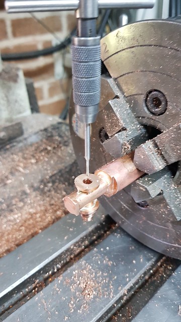 20190224_121332 20190224_121332 by Anne Froud, on Flickr These ones in the top are dummies of course, but they're done in the same way with a scrap of M1.4 thread and a nut. This is a 1.1mm diameter PCB drill. I'm only going in 0.5mm and then finishing with a HSS drill. If I break off a Carbide drill in this, I'm in trouble!  20190224_122021 20190224_122021 by Anne Froud, on Flickr The Brass filter finger will be soft soldered to the two remaining legs of this extension  20190224_184722 20190224_184722 by Anne Froud, on Flickr The wall is only 0.6mm thick, another reason not to use Brass for this! It was going to be 0.5mm thick, but looking again at the model I decided it could go up a fraction. It's still mighty thin though, so the cuts were done very gingerly.  20190224_223546 20190224_223546 by Anne Froud, on Flickr Just the tidying up of the parted off end needs to be done and then this part is finished. 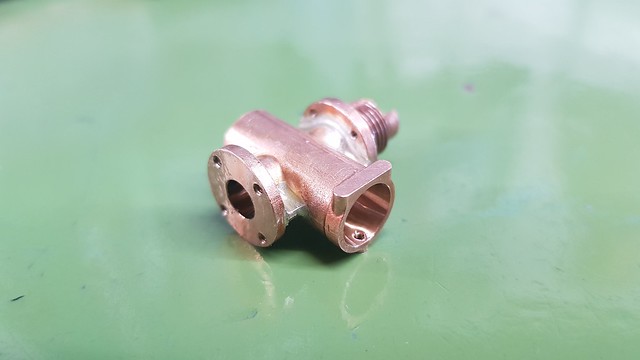 20190224_224305 20190224_224305 by Anne Froud, on Flickr |
|
|
|
Post by Oily Rag on Feb 24, 2019 22:57:35 GMT
Great sentiments, I love it! I especially agree with Brian's comment "Every person who has slaved away to produced a finished locomotive deserves nothing but praise & plenty of it." Making stuff is an absolute joy, regardless of the quality of workmanship, and I really enjoy seeing anything and everything someone has had the drive to turn into a physical reality. I do intend to exhibit 1501 eventually, it gives an excuse to meet up with like minded souls and chew the fat.
and
"entering a competition"
Please share via exhibiting |
|
|
|
Post by 92220 on Feb 25, 2019 8:38:36 GMT
Hi Roger. They look good!! I boil my silver soldered parts in water to clean the flux off. I've not had much success in the ultrasonic tank. Do you use any special ultrasonic solution or run it at an elevated temperature? Bob. Thanks Bob, I use this from eBay which works pretty well with it heated to 40C in the tank. If you look at the awful video, you can see that I don't like to get things any hotter than absolutely necessary, and for the shortest possible time. The part barely gets noticeably red and then it's done. For most of the heating time, I'm only heating the bar in the vice. This is one reason why I always put the Silver Solder wire in place rather than try to apply it when it's hot. I think the flux comes off so easily because of this. Thanks for that link Roger. I'll get some of that. Bob. |
|
|
|
Post by delaplume on Feb 25, 2019 9:00:39 GMT
I use that too in my Ultrasonic cleaner for bike carbs-----------seems OK
|
|
|
|
Post by Roger on Feb 25, 2019 20:15:14 GMT
I've tidied up the ends of the valves now and made the gland piece from Brass. There's a 4.1mm diameter pocket 1.1mm deep to take an 'O' ring which seals on the 2.5mm shaft. The outside takes a 1mm section 'O' ring too.  20190225_194854 20190225_194854 by Anne Froud, on Flickr I still have to make the valve element, but while I've been doing the glands I thought I'd have a go at the elbow and see what happens.  Injector water inlet elbow Injector water inlet elbow by Anne Froud, on Flickr The stock was turned down to 20.5mm to reduce the amount of material needing to be milled away. It's still a lot though. 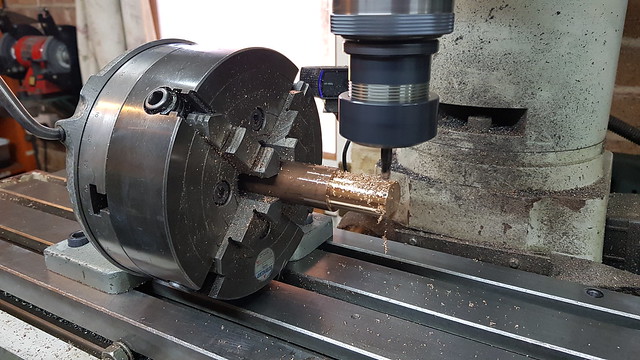 20190225_122503 20190225_122503 by Anne Froud, on Flickr I'm using a 5.5mm diameter 3-flute carbide cutter with 0.5mm deep cuts and 50mm/min 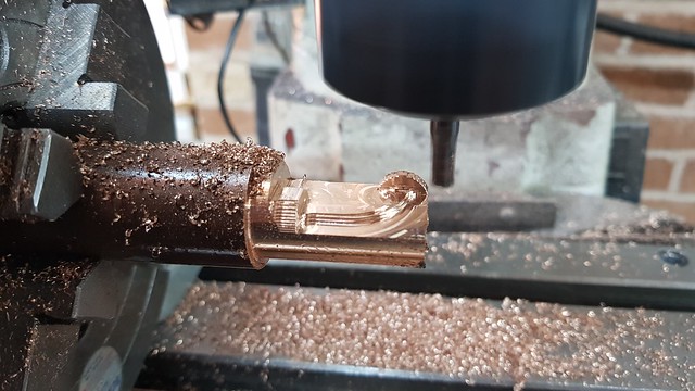 20190225_142711 20190225_142711 by Anne Froud, on Flickr Here's a wobbly video to show what that looks like. 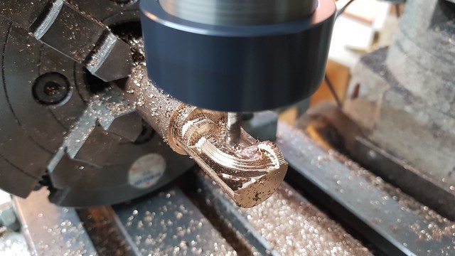 20190225_143535 20190225_143535 by Anne Froud, on Flickr That's as far as we go, roughing from the top.  20190225_145934 20190225_145934 by Anne Froud, on Flickr The bottom was roughed with a 10mm cutter, but it's obviously got quite hot in the process. On balance I would probably have been better off off only partially doing this so as to leave more support when finishing the top.  20190225_181252 20190225_181252 by Anne Froud, on Flickr 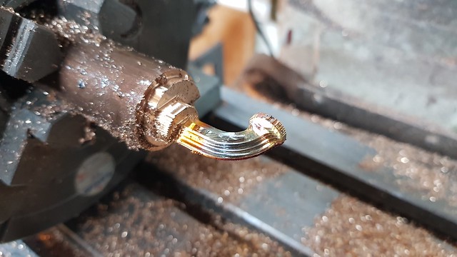 20190225_181516 20190225_181516 by Anne Froud, on Flickr This is a 3mm radius mill with a 0.5mm corner which is getting into the tight radii in most places. 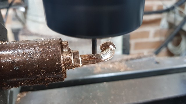 20190225_192202 20190225_192202 by Anne Froud, on Flickr A 1mm cutter is used to clean up the flange parts which that can't reach. |
|
JonL
Elder Statesman
 WWSME (Wiltshire)
Posts: 2,909
|
Post by JonL on Feb 25, 2019 20:30:03 GMT
So I'm assuming you will solder two halves together? Do you leave a register or similar for them to align with?
|
|
|
|
Post by Roger on Feb 25, 2019 23:39:32 GMT
So I'm assuming you will solder two halves together? Do you leave a register or similar for them to align with? Yes, the two halves will be Silver Soldered together. I will need some sort of plate or ring on the ends to hold it together, or I might add a pin on one end where it's next to the chuck at the moment. It definitely needs something to positively locate the parts together. |
|
|
|
Post by delaplume on Feb 26, 2019 0:24:56 GMT
Hi Roger-----don't forget to represent the two pins that you can see on that flat, oval surface.....They secure the top plate in-situ on the full-size..
IIRC they are tapered with split ends...
|
|
|
|
Post by Roger on Feb 26, 2019 8:07:06 GMT
Hi Roger-----don't forget to represent the two pins that you can see on that flat, oval surface.....They secure the top plate in-situ on the full-size.. IIRC they are tapered with split ends... Hi Alan, I didn't realise that's what those were, I'll see if I can do something about adding those. It's a pity I didn't realise before when it was all set up and I could easily find the positions. It's not the end of the world if I leave them off though. |
|
|
|
Post by Roger on Feb 26, 2019 12:28:15 GMT
Just a quick 'heads up' on the April edition of "Model Engineers' Workshop" magazine which will be featuring my design for a workshop travelling crane. I made mine long before I became obsessed with photographing everything, so I didn't have enough pictures to submit an article. When the second one was made for a friend's larger workshop, I took loads more and thought it might interest a few people. None of us are getting any younger, and it solves the problem of moving locomotives and equipment around the workshop.
|
|
rrmrd66
Part of the e-furniture

Posts: 339 
|
Post by rrmrd66 on Feb 26, 2019 16:51:47 GMT
I would like to be the first to offer my congratulations to Roger for achieving, in the next few days, 500 pages of thread on the topic of Speedy/1501.
I am absolutely certain that I will not be the only one to send such a message and not the only one to always read Roger's latest post first of all.
The fact that he is able to describe his painstaking work with such clarity and avoid waffle is noteworthy.
I had the pleasure of meeting Roger at last years Doncaster ME show where he showed me and others the exquisite detail he has achieved.
How he runs a consultancy and write this thread at the same time I am not too sure.
Anyway, that's enough.
Good on you Roger. Long may it continue
regards
Malcolm
|
|
|
|
Post by Roger on Feb 26, 2019 17:43:02 GMT
I would like to be the first to offer my congratulations to Roger for achieving, in the next few days, 500 pages of thread on the topic of Speedy/1501. I am absolutely certain that I will not be the only one to send such a message and not the only one to always read Roger's latest post first of all. The fact that he is able to describe his painstaking work with such clarity and avoid waffle is noteworthy. I had the pleasure of meeting Roger at last years Doncaster ME show where he showed me and others the exquisite detail he has achieved. How he runs a consultancy and write this thread at the same time I am not too sure. Anyway, that's enough. Good on you Roger. Long may it continue regards Malcolm Thanks Malcolm, that's really kind of you. it's quite a milestone, not one I would have ever expected to reach when I started with just a couple of quick questions! You'll see that the style has changed quite a bit over the years, with much more by way of pictures and less text. I think it gets the message across just as well and doesn't put you to sleep. The thousands of replies and invaluable nuggets of information keep me motivated, so without you all I would never have got this far. I intend to visit the Doncaster show again this year, so it would be great to meet up again, and hopefully see some of the things you've all been working on. |
|
|
|
Post by Roger on Feb 26, 2019 22:16:30 GMT
Ok, the first attempt at the elbow isn't going to end well, so it's best to have another go. The problem is that it's distorted too much from removing the bottom part, something I did think about but didn't act upon. Such is life. So here's a wobbly video of that being parted off. I show this because I've read on many occasions how Carbide tools are brittle and intermittent cuts aren't possible. This is being done under power which guarantees an even tool load. Seconds out, round 2! This is the same roughing cut on the top as last time with the exception that I've left another 50 microns stock, ie 0.35mm now. 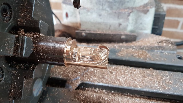 20190226_203001 20190226_203001 by Anne Froud, on Flickr Then it was taken to 0.15mm stock with the 3mm corner mill with 0.5mm radius. Yes, it looks a mess, but the idea is just to rough out as much material as possible in a short time. This has taken about three hours to get to this point. I'm not pushing it that hard because I want the tools to last. The next challenge is to get into those corners the 3mm diameter cutter couldn't reach.  20190226_220134 20190226_220134 by Anne Froud, on Flickr |
|
dscott
Elder Statesman
Posts: 2,438
|
Post by dscott on Feb 27, 2019 3:07:12 GMT
Yes Congratulations Roger on the 500 pages!!
I think we all have learned such a lot from the pages and also formed friendships within the 1500 builders group.
Sunday saw us pick up a set of wheels for ours... and today almost completed a fettling of one of them.
This is the trouble when you have several photos to hand of what the full size looks like and you are filing it down to resemble!
It turns out that Norman Spink had the best patterns now via Blackgates.
On a lighter note. I have managed to buy a superb pair of Great Western couplings complete with square cut thread etc... Etc.
It was Lily that pointed out to me "That they seemed to be attached to a very large Green Locomotive model, and it may just go in the car!!" 4121 just needs a sister now who insists on wearing Black on every occasion!
Best regards.
David and Lily. What would you want for your 60th Birthday??
|
|
|
|
Post by Roger on Mar 1, 2019 20:17:01 GMT
I managed to cock up the last attempt at the elbow, so here's a revised version to take advantage of the fact I have to start again. This time I've added tiny lugs to the part which have 1mm holes for rivets. The idea is to rivet the two halves together then cut these off. I don't know why I didn't think of this before, it seems an obvious thing to do now. 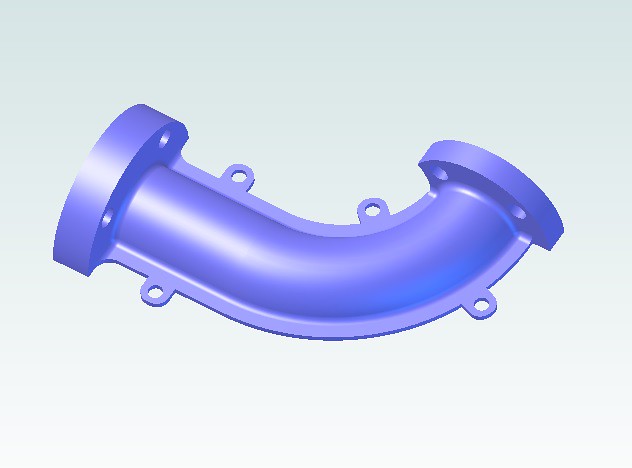 Injector water elbow with lugs Injector water elbow with lugs by Anne Froud, on Flickr So here it is at close of play tonight with the horizontal roughing complete and a pass with the 3mm Radius mill that has a 0.5mm corner radius. You can just see the lugs emerging at this point. I've created a profile for the cutter to trim around the edge so the next size cutter will have a well defined edge profile. The same program will be used next with the 1.5mm end mill to tidy it up before final finishing  20190301_195249 20190301_195249 by Anne Froud, on Flickr |
|
|
|
Post by delaplume on Mar 1, 2019 20:47:50 GMT
It's a modern take on the old adage that the sculptor "sees" the finished article within the original block of Granite, isn't it ??
"Some Hammer---------Some chisel", to freely mis-quote !!
|
|
dscott
Elder Statesman
Posts: 2,438
|
Post by dscott on Mar 2, 2019 0:44:06 GMT
I did in fact take a chisel and hammer to the wheel in the vice today to get a clean line where the spokes go into the
balance weight! I have done the middle drivers on two so far having picked them up from the Blackgates stand just after we had lunch with Delaplume in Oldham on Sunday! A Super Exhibition where we got 1 and 2 tickets we were so early! And best parking space!
Lack of visitors but so many people on various stands to chat with. Think early Thornbury... Yes went to them all!
30 photos of 1501's wheel so no excuse on not getting them right! Friday sees me digging out the weight to represent the spaces left from uneven filling up with lead between the spokes!!!
Love from David and Lily.
|
|
|
|
Post by Roger on Mar 2, 2019 8:07:57 GMT
I did in fact take a chisel and hammer to the wheel in the vice today to get a clean line where the spokes go into the balance weight! I have done the middle drivers on two so far having picked them up from the Blackgates stand just after we had lunch with Delaplume in Oldham on Sunday! A Super Exhibition where we got 1 and 2 tickets we were so early! And best parking space! Lack of visitors but so many people on various stands to chat with. Think early Thornbury... Yes went to them all! 30 photos of 1501's wheel so no excuse on not getting them right! Friday sees me digging out the weight to represent the spaces left from uneven filling up with lead between the spokes!!! Love from David and Lily. Hi David, I hope your castings are better than the ones I got, because the middle boss is completely wrong on mine. The boss should stand out more and there's a pronounced radius on it. The ones I have are flat, flush with the spokes. I suppose you could add a piece to that after machining it flat so there's material there to make it look right. If I was doing it again, I'd get the wheels cast so they were right in the first place. Note that the driving wheels have an over size balance weight attached and that there are plates bolted through on all of the wheels to contain lead for the same purpose. I added sheet metal plates, secured with Devcon on mine. I should have included the bolt holes too really, but I thought they were unsightly. I'd do that too if I was to do it all again. |
|
|
|
Post by jon38r80 on Mar 2, 2019 12:03:56 GMT
I Think that while you were adding the ears you should have included one on the outside of the curve of the quadrant. uless its lens distortion causing it , that looks like where you had a lot of distortion in the first machining.
I think I would have put one there anyway to stop it opening up when soldering the halves. Possibly just a nice to have but while you are at it?
|
|
|
|
Post by Roger on Mar 2, 2019 14:46:14 GMT
I Think that while you were adding the ears you should have included one on the outside of the curve of the quadrant. uless its lens distortion causing it , that looks like where you had a lot of distortion in the first machining. I think I would have put one there anyway to stop it opening up when soldering the halves. Possibly just a nice to have but while you are at it? Hi Jon, Good point but I cant' change it now I'm afraid, it's being machined. The first one probably distorted because I was a bit heavy handed with the machining. Hopefully this time it won't happen. It got very hot, so I'll take more time over that this time. It's not easy for the heat to get away when it nears the finished size, so I'll have to slow down as it gets thinner. Since the underside is completely flat, I can afford to leave a bit of spare material on there and see what it ends up like before taking the finishing cut. If the worst comes to the worst, I'll put a toolmaker's clamp on the middle of it to make sure it behaves. |
|


