|
|
Post by Roger on Aug 13, 2019 19:46:04 GMT
Time for another fixture, this time to hold each of the hinged window frames for adding the extra magnet holes. This is the retainer which is just copied from the window glass model and a couple of holes added.  20190813_134904 20190813_134904 by Anne Froud, on Flickr This was copied from the assembly fixture and modified to suit this purpose.  20190813_195500 20190813_195500 by Anne Froud, on Flickr The idea is to locate off the inner edge of the frame and hold it down by the rebate where the glass fits.  20190813_195556 20190813_195556 by Anne Froud, on Flickr The new magnet pocket was designed with a 1mm cutter in mind for creating the ears.  20190813_202331 20190813_202331 by Anne Froud, on Flickr |
|
|
|
Post by silverfox on Aug 13, 2019 20:23:27 GMT
Roger
rebait ( with a hyphen, is what you do when fishing)
Rebate is the word you are looking for (lol), BUT it doesn't detract from you work, better you make an error on spelling that the window
Ron
|
|
JonL
Elder Statesman
 WWSME (Wiltshire)
Posts: 2,909
|
Post by JonL on Aug 13, 2019 20:37:20 GMT
I always wondered why my adjustable spanner had a digital readout...
Superb work Roger, the ears for excess glue to pool is a great idea.
|
|
|
|
Post by Roger on Aug 13, 2019 21:17:30 GMT
Roger rebait ( with a hyphen, is what you do when fishing) Rebate is the word you are looking for (lol), BUT it doesn't detract from you work, better you make an error on spelling that the window Ron Hi Ron, Quite so, or a rabbet if you're going more old fashioned nomenclature. Duly changed! No hyphen in rebait though... |
|
|
|
Post by silverfox on Aug 13, 2019 22:52:41 GMT
Depends what fishing club you belong to lol
Clean forgot about rabbet And me knowing Chas as well!
|
|
Gary L
Elder Statesman
Posts: 1,208
|
Post by Gary L on Aug 13, 2019 23:58:19 GMT
Left handed digital calipers would be easier to use than right handed on the lathe Very much so- I bought one from MDRO at an exhibition a year or two back. I use it all the time to calibrate fresh tools to the DRO and I am not sinistral at all. Much easier on the lathe than 'normal' callipers, and no mistakes in reading it. The micrometer only comes out for special occasions. :-) -Gary |
|
|
|
Post by steamer5 on Aug 14, 2019 1:36:49 GMT
Hi Roger,
It’s probably to late but could of just putting extra magnets on the knob end of the window been enough to stop it popping open?
Now I’ve got to find a left hand caliper.........
Cheers Kerrin
|
|
|
|
Post by Roger on Aug 14, 2019 7:09:17 GMT
Hi Roger, It’s probably to late but could of just putting extra magnets on the knob end of the window been enough to stop it popping open? Now I’ve got to find a left hand caliper......... Cheers Kerrin Hi Kerrin, Those were my thoughts too, but then I thought if it had to go up again for machining, I might as well add more all the way round. I'll have to make a miniature crowbar to get them off at this rate! |
|
|
|
Post by silverfox on Aug 14, 2019 8:55:23 GMT
Roger
That surely is not beyond your capabilities?
'Say it aint so' ( Baseball fans will undrstand that)
|
|
|
|
Post by Roger on Aug 14, 2019 16:38:18 GMT
This is the first of the modified window frames with the pockets for the glue. I've decided that I'd be better off not using the Gel type of Superglue, it's too thick. I'll probably use a thinner Loctite product instead. Out of interest, you can see a strange pattern on the face of the Aluminium fixture that you won't have seen before. This is my first use of the 'High speed pocketing' CAM function which does some progressive spiral cuts instead of going round the profile. I imagine this is the same as what Fusion360 calls Adaptive machining, where the chip load never exceeds a maximum, allowing you to go faster without breaking cutters when you dive into an internal corner. That might come in handy when machining with very small cutters, we'll see. 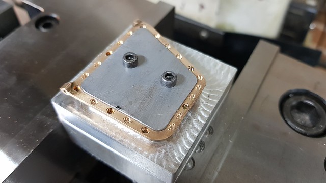 20190814_121824 20190814_121824 by Anne Froud, on Flickr This is the last of the frames, and it's still got the magnets in it which can't be removed. I'm not happy with it, they're slightly proud of the position I want them, so they've got to go. Here I'm drilling out the bulk of the magnet with a 1.85mm diameter carbide PCB drill...  20190814_145523 20190814_145523 by Anne Froud, on Flickr ... followed by 1mm cutter to gingerly remove them 0.1mm deep at a time. I did manage to set fire to one of them by going a little too fast. Don't believe what people tell you about this on the internet, it's perfectly possible to machine magnets with Carbide tools. Heat can be a problem though, and the dust it toxic and highly inflammable, so you don't want to be doing much of this. By all accounts, you shouldn't machine Neodymium magnets if you want them to be used afterwards. Cutting through the protective plating will allow them corrode over time, thus destroying their magnetic properties. Still, it's handy to know that you can at least machine them if you need to get them out.  20190814_151400 20190814_151400 by Anne Froud, on Flickr |
|
timo
E-xcellent poster
 Completing 3 1/2 Rainhill .Building 5" Railmotor and waiting to start 3 1/2" King
Posts: 234
|
Post by timo on Aug 14, 2019 20:55:32 GMT
Roger,
Fascinating and impressive stuff.
Tim
|
|
|
|
Post by Roger on Aug 15, 2019 10:26:59 GMT
I'm trying to move on with the cab a bit more, so that means finishing the reverser. I didn't realise when I made it that there was a boss on the bottom of the lever, so it's time to add that now. The boss was made a close fit inside the existing 4mm reamed hole so it would line up when it was Silver Soldered  20190814_202004 20190814_202004 by Anne Froud, on Flickr I made it a bit longer than necessary and drilled out the middle most of the way through to give a reference when clocking it up later and also making it easier to lightly peen the end over to hold it in place. The shoulder of the boss has a slight taper on it so the Silver Solder will definitely penetrate the whole face.  20190814_202022 20190814_202022 by Anne Froud, on Flickr  20190814_211621 20190814_211621 by Anne Froud, on Flickr It's the usual setup, smothered in flux and an arc of Silver Solder that snugly fits the joint. That had to be nudged back in place a few times with the Titanium welding wire poker to get it in the right place when it was hot enough to make the flux melt and go clear.  20190814_212410 20190814_212410 by Anne Froud, on Flickr You can see it's actually penetrated right through to this side too...  20190815_073845 20190815_073845 by Anne Froud, on Flickr ... and left a nice big fillet on this side to make it strong.  20190815_073854 20190815_073854 by Anne Froud, on Flickr The lathe is big enough to swing this, and the drill shank was a nice snug fit in the hole for clocking it up.  20190815_094154 20190815_094154 by Anne Froud, on Flickr Then it was drilled and reamed to 4mm, removing 99% of what was in the original hole.  20190815_095207 20190815_095207 by Anne Froud, on Flickr The hole came out nicely central so I'm happy with that.  20190815_095613 20190815_095613 by Anne Froud, on Flickr  20190815_095622 20190815_095622 by Anne Froud, on Flickr I'd already made a flat plate that I was going to use for the flanged part of the pivot. The holes in that were 2mm which is actually too big, so I've used the opportunity to redesign it as one piece to include the pivot shaft. I've kept the pivot as 4mm but reduced the end that you can see to 3mm so it creates the illusion that the whole shaft is 3mm. The reverser is retained with a washer and split pin, one of the giant 0.8mm variety, not my miniature ones! The idea is to tap the holes in the flange M1.6 which will keep the bolts in place when it's assembled from the back. This part needs to be removed to release the pole reverser so it can be slid upwards through the floor of the cab. The bracket has two clearance holes in it, so the bracket can slide forwards with the bolts in place and nuts and washers added to the front to hold it on.  20190105_180452 20190105_180452 by Anne Froud, on Flickr |
|
|
|
Post by Roger on Aug 15, 2019 21:39:07 GMT
Having added a boss to the reverser, it's now impossible to pass through the cab floor, so this is the second of many alterations to the 3D printed one before I make it in Steel.  20190815_100740 20190815_100740 by Anne Froud, on Flickr This is the bottom pivot for the pole reverser. Yes, it's sticking up way too far out of the chuck, but it's a small piece of EN8 I don't really want to cut down and it won't pass through the hole in the middle. I'll take it easy and it won't be a problem.  20190815_210154 20190815_210154 by Anne Froud, on Flickr The holes are tapped M1.6 to keep the bolts attached to the flange when it's unbolted and pushed back through the bracket.  20190815_211335 20190815_211335 by Anne Froud, on Flickr Flipping the tilting rotary table over 90 degrees is never going to line up spot on, so I'm using the wobbler on both sides and the end to find the centre of the split pin hole. I've had to rotate the table by 90 degrees too.  20190815_211842 20190815_211842 by Anne Froud, on Flickr A 0.85mm Carbide PCB drill is just the right size for my second from smallest split pins  20190815_213325 20190815_213325 by Anne Froud, on Flickr Parted off long, turned round and faced to length.  20190815_220243 20190815_220243 by Anne Froud, on Flickr This is how it looks assembled on the chassis...  20190815_222428 20190815_222428 by Anne Froud, on Flickr ... and this is what it ought to look like. It's close enough.  DSCN5654 DSCN5654 by Anne Froud, on Flickr |
|
|
|
Post by Roger on Aug 16, 2019 21:22:00 GMT
This is the M1.6 hole for the tension spring on the pole reverser. I hadn't got a spring in mind when I made this, but now I've got one so it's time to finish it off. 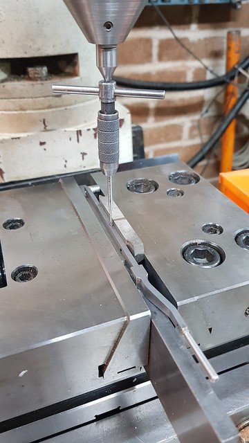 20190816_131324 20190816_131324 by Anne Froud, on Flickr I've had to slightly adjust the forward end stop because the reverser didn't quite drop into full forward gear.  20190816_134155 20190816_134155 by Anne Froud, on Flickr There's still a cover plate to go on the far side of this, so you won't see the spring from that side. On this side there's a vacuum tank that can hide the reversing rod and the connection. It's a bit wobbly because I'd only bolted it to the 3D printed base, but it's good enough for the moment.  20190816_210957 20190816_210957 by Anne Froud, on Flickr The next piece to make is the reversing rod that goes from here to the gear frame. I agonised over this (don't I always!) because it's not in line with the pole reverser, there's a 9mm run on it that means the rod has to be bent slightly. I'd prefer for it to be straight, but that would mean having twisting forces on the pole reverser and that's not a good idea. The other issue is that thickness of the rod which is 4mm wide. That's not a standard stock thickness for any Mild Steel strip or sheet. In the end, I looked up the cost of 4mm Gauge plate and found to my surprise that I can get a piece 4mm x 50mm x 500mm from eBay for £13.61 including VAT and delivery! So that solves the problem of the thickness and also makes it much more rigid since there's a curved end to it that will try to bend the whole rod when a force is applied lengthwise. The windows haven't been forgotten, I'm just bonding magnets at the moment. |
|
dscott
Elder Statesman
Posts: 2,438
|
Post by dscott on Aug 17, 2019 0:43:24 GMT
For the first time in History when driving a model 1500 Class locomotive... Your finger is not thrust into the boiler when putting her into full forward gear!!!! WOW. Here is to full scale (On the outside) Scale models which are incredibly satisfying!
I got into a wonderfully tease chat with a guy at the Rugby Club Big Four Rally last Weekend. We had ascertained the 4701 in 7 1/4 should have the larger Boiler or change the number to 4700 which ran with the number 1 boiler as they had lots of them. Keith Wilson did not have all the drawing at the time. BUT later when building 10 1/2 inch gauge versions did the bigger boilers on them. Huge beasts! I told of my latest quicky, which harnesses disabled Buggy motors, gear boxes and batteries twice in 2 units. A difficulty in the choice of either M8 or M10 bolts for various bits... Held in place with Nylock Nuts of course!! They are just about liftable without the battery!
They let us stay for the rest of the afternoon??
The GREAT WESTERN was well represented with a Grange in 7 1/4 and in 5 inch a King, Manor, Big Prairie, Pannier and an ancient 2-4-0 tender model. It was the Manors first outing and she continued in spite of the heavy rain. I got about half a pint out of the Big Prairie bunker before putting her in the car!
|
|
|
|
Post by Roger on Aug 17, 2019 19:39:57 GMT
I'm just by bullying my family into setting up free Flickr accounts so I can continue to post photos here. Normal service will resume shortly...
|
|
|
|
Post by delaplume on Aug 18, 2019 17:41:32 GMT
Hi Roger,
Just for information}----- Quote..."The next piece to make is the reversing rod that goes from here to the gear frame."....This is known as the Reach Rod and attaches to the cross shaft which, as its' name suggests crosses over the width of the chassis from one gear frame to the other.....
Attached to the cross shaft at each of the outside points is a lifting arm and from this is an attachment to the sliding die block...( Remember, although this is a GWR 2-Cyl loco it has outside Walshaerts valve gear, not Stephensons ).......Please do remember to make you cross-shaft / lifting arm assembly such that both lifting arms are dead parallel to one another........Any errors here will set one cylinders events either leading or trailing the 90 degree quatering you've so carefully assembled.....
Alan
|
|
|
|
Post by Roger on Aug 18, 2019 18:06:59 GMT
Hi Roger, Just for information}----- Quote..."The next piece to make is the reversing rod that goes from here to the gear frame."....This is known as the Reach Rod and attaches to the cross shaft which, as its' name suggests crosses over the width of the chassis from one gear frame to the other..... Attached to the cross shaft at each of the outside points is a lifting arm and from this is an attachment to the sliding die block...( Remember, although this is a GWR 2-Cyl loco it has outside Walshaerts valve gear, not Stephensons ).......Please do remember to make you cross-shaft / lifting arm assembly such that both lifting arms are dead parallel to one another........Any errors here will set one cylinders events either leading or trailing the 90 degree quatering you've so carefully assembled..... Alan Hi Alan, I had a feeling that was the wrong term for it. I've already made the cross shaft and taken great care to get both sides lined up with each other, so hopefully that will be ok. |
|
|
|
Post by delaplume on Aug 18, 2019 19:30:26 GMT
-------cross-shaft also known as Weighshaft
|
|
|
|
Post by Roger on Aug 18, 2019 19:49:53 GMT
This is how the reverser looks on 1501 with the thin cover plate on the inside of the quadrant. I'm guessing that the curved sheet metal item is some sort of heat shield to protect the driver from the heat of the fire. You can see a foot hold on the back of the quadrant to assist in heaving on the lever. I'll be making that shorly.  Reverser Reverser by Timothy Froud, on Flickr The cover plate is a bit battered! 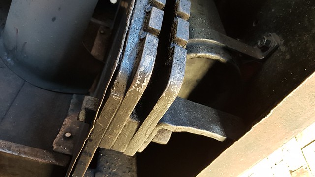 Reverser3 Reverser3 by Timothy Froud, on Flickr I'm making it from coiled up Shim Steel which is magnetic, so presumably a high carbon Steel of some kind. It was a struggle to uncoil it enough to guillotine a bit off and then fight it back into its tin. Welding gloves helped to avoid getting a nasty cut. Here I've made a sandwich with a top plate which is dowelled through the stock and into the bottom as well where the two fixing holes are.  20190817_113103 20190817_113103 by Timothy Froud, on Flickr I treated the job as if it was the thickness of the Shim plus the top cover plate.  20190817_120213 20190817_120213 by Timothy Froud, on Flickr It's a bit scruffy, I left tabs but probably could have done without them in hindsight.  20190817_120335 20190817_120335 by Timothy Froud, on Flickr Anyway, the guillotine got rid of the bulk of the unwanted material... 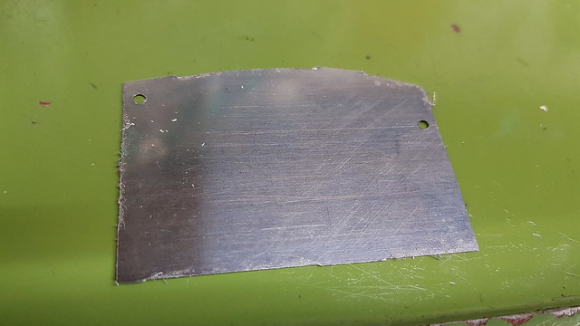 20190817_120618 20190817_120618 by Timothy Froud, on Flickr ... which was filed away, using the quadrant as a support and filing guide.  20190817_121558 20190817_121558 by Timothy Froud, on Flickr It came out good enough in the end with a little careful filing. 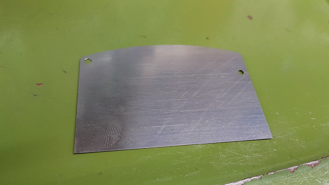 20190817_123214 20190817_123214 by Timothy Froud, on Flickr 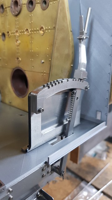 20190817_125916 20190817_125916 by Timothy Froud, on Flickr  20190817_125936 20190817_125936 by Timothy Froud, on Flickr |
|


