|
|
Post by Roger on Dec 2, 2019 22:19:51 GMT
Ok, I've decided to go ahead and machine the base plate of the cab. I got this piece of plate some time ago and fly cut it on both sides. The idea is the same as I used on the bunker, ie the plate has raised edges where you would normally expect there to be angles attached, and the outside is machined so that you get the very thin base showing on the outside that the cab sides sit down on. This allows the plate to actually be 1.5mm thick across, even though the apparent thicknes is 0.5mm as seen from the outside. It also guarantees that everything is nice and square and to the right dimensions with the fixing holes all in the right places. Here I'm drilling some 8mm holes for the clamps I made for the bunker.  20191202_200829 20191202_200829 by Timothy Froud, on Flickr You can't see the clamps from here, but they bolt down to Tee nuts and have an M8 thread to one side so you can pick up holes that aren't in line with the Tee slots. I'll show them later when I break it down. I've used as many clamps as possible to make sure this doesn't move. The M8 bolts at the front are done up fairly tightly onto packing. Here I'm running the clock all over the surface to see how flat it is. It's all within 60microns, just over 2 thou so it's good enough. The two additional stops on the front left and right are just to make sure it can't move sideways. I haven't got enough clamps to be able to do the same on the other side. I ought to make some 'L' shaped pieces really for this sort of thing so they can contain opposite corners.  20191202_210309 20191202_210309 by Timothy Froud, on Flickr Anyway, now you can see the logic behind where those fixing holes are. Having the 3D printed base plate makes this sort of visualisation much easier for the setup. I've loaded the profile roughing program and done a sanity check to see if I can reach all round. It's clear that I'll need to change the cutter diameter to something smaller than the 5.5mm one I've selected though. That's because it gets perilously close to the rear M8 cap screws and will interfere with the clamps too. They'll almost certainly have to be moved when I get that far. With jobs like this you need to take your time and plot your way through it step by step. I never rush these things because it's so easy to make a mistake and scrap the job.  20191202_211340 20191202_211340 by Timothy Froud, on Flickr Although that seems like a lot of metal to remove, it doesn't take that long with a 16mm cutter taking 1mm deep cuts. Here's a wobbly video to give some sort of idea of the feed and speed.  20191202_215602 20191202_215602 by Timothy Froud, on Flickr |
|
Gary L
Elder Statesman

Posts: 1,208
|
Post by Gary L on Dec 3, 2019 1:59:07 GMT
Ok, I've decided to go ahead and machine the base plate of the cab. I got this piece of plate some time ago and fly cut it on both sides. The idea is the same as I used on the bunker, ie the plate has raised edges where you would normally expect there to be angles attached, and the outside is machined so that you get the very thin base showing on the outside that the cab sides sit down on. This allows the plate to actually be 1.5mm thick across, even though the apparent thicknes is 0.5mm as seen from the outside. It also guarantees that everything is nice and square and to the right dimensions with the fixing holes all in the right places. [Snip] Erm, how sure are you about that edge Roger? I've looked very hard at the various photos and come to the conclusion that there is an anomaly on the RHS of 1501, where a plate edge is visible especially towards the bunker, at least on the pre-overhaul photos. On the LHS, particularly the cab front, there is definitely no edge visible. The Paddington drawings show the cab sheets sitting on top of the footplate throughout, but I am not convinced. I formed the conclusion that the design intention was that the cab side sheets overlap and thus protect the edge of the footplate sheet (which makes perfect sense structurally), but at the rear, especially under the bunker, the visible edge on 1501 is a result of subsequent patching to deal with corrosion damage. I could be wrong about this; and the footplate edge definitely protrudes at the very rear, over the buffer beam, in order to provide a footstep of sorts, and a place to mount the lamp irons. Photos can be ambivalent, particularly where the view is not a close-up. Rust creeping up from the lower edge under the paint can look very like a plate edge from a distance. Early black-and-white photos don't seem to show any such edge in the side view, and the rivets are spaced further from the edge at the bottom of the side sheets than they are at the front corners. Not conclusive, but this is what you would expect if the sides were overlapping the footplate edge and possibly carried down a little beyond. Just because the prototype is (perhaps) built in a certain way, does not mean we have to follow suit of course, especially if it suits our own methods better, but maybe someone who has worked on 1501 could comment? -Gary |
|
|
|
Post by Roger on Dec 3, 2019 8:13:05 GMT
Ok, I've decided to go ahead and machine the base plate of the cab. I got this piece of plate some time ago and fly cut it on both sides. The idea is the same as I used on the bunker, ie the plate has raised edges where you would normally expect there to be angles attached, and the outside is machined so that you get the very thin base showing on the outside that the cab sides sit down on. This allows the plate to actually be 1.5mm thick across, even though the apparent thicknes is 0.5mm as seen from the outside. It also guarantees that everything is nice and square and to the right dimensions with the fixing holes all in the right places. [Snip] Erm, how sure are you about that edge Roger? I've looked very hard at the various photos and come to the conclusion that there is an anomaly on the RHS of 1501, where a plate edge is visible especially towards the bunker, at least on the pre-overhaul photos. On the LHS, particularly the cab front, there is definitely no edge visible. The Paddington drawings show the cab sheets sitting on top of the footplate throughout, but I am not convinced. I formed the conclusion that the design intention was that the cab side sheets overlap and thus protect the edge of the footplate sheet (which makes perfect sense structurally), but at the rear, especially under the bunker, the visible edge on 1501 is a result of subsequent patching to deal with corrosion damage. I could be wrong about this; and the footplate edge definitely protrudes at the very rear, over the buffer beam, in order to provide a footstep of sorts, and a place to mount the lamp irons. Photos can be ambivalent, particularly where the view is not a close-up. Rust creeping up from the lower edge under the paint can look very like a plate edge from a distance. Early black-and-white photos don't seem to show any such edge in the side view, and the rivets are spaced further from the edge at the bottom of the side sheets than they are at the front corners. Not conclusive, but this is what you would expect if the sides were overlapping the footplate edge and possibly carried down a little beyond. Just because the prototype is (perhaps) built in a certain way, does not mean we have to follow suit of course, especially if it suits our own methods better, but maybe someone who has worked on 1501 could comment? -Gary Hi Gary, I've probably not explained that as well as I should have. The sides don't have a significant amount of the base plate protruding, but it's certainly visible. That's why I'm making that edge where the side sheet comes down to 0.5mm thick because it does show. The back of the bunker is where it does stand out from the sheet though, as you mentioned. The main purpose of machining from solid is to combine those features into one piece that has a 1.5mm thickness over most of it, only reducing right at the edge. If you have angles riveted to the inside, the thickness of the angle then poses a problem for the rivets that come from the outside because they come where the foot of the angle is. With the base of the 'angle' missing, you can just get rivets in the right places through to where they can be formed over. |
|
|
|
Post by Roger on Dec 3, 2019 11:58:25 GMT
Good progress on the cab footplate, it's now got just one more cut to finish roughing the middle out. This is one cut down.  20191203_081614 20191203_081614 by Timothy Froud, on Flickr So while that's busy munching metal, I thought I'd tack up the plinths ready for Silver Soldering. It's a fiddly process getting the edges nicely square and butted up against each over, requiring a lot of patience and clamps.  20191203_102905 20191203_102905 by Timothy Froud, on Flickr  20191203_103304 20191203_103304 by Timothy Froud, on Flickr  20191203_103816 20191203_103816 by Timothy Froud, on Flickr  20191203_104303 20191203_104303 by Timothy Froud, on Flickr Some tacks are better than others. One or two stubbornly refused to bridge the gap and a little filler was needed. That inevitably results in a big blob that needs filing off later.  20191203_104717 20191203_104717 by Timothy Froud, on Flickr  20191203_105518 20191203_105518 by Timothy Froud, on Flickr It's very easy to stray too close to the edge and lose the corner. Fortunately this one won't be seen and it's only tiny anyway.  20191203_111510 20191203_111510 by Timothy Froud, on Flickr  20191203_113026 20191203_113026 by Timothy Froud, on Flickr  20191203_114720 20191203_114720 by Timothy Froud, on Flickr I'll clean those up and make sure they're all looking right and then Silver Solder them. |
|
Gary L
Elder Statesman
Posts: 1,208
|
Post by Gary L on Dec 3, 2019 12:17:22 GMT
Erm, how sure are you about that edge Roger? I've looked very hard at the various photos and come to the conclusion that there is an anomaly on the RHS of 1501, where a plate edge is visible especially towards the bunker, at least on the pre-overhaul photos. On the LHS, particularly the cab front, there is definitely no edge visible. The Paddington drawings show the cab sheets sitting on top of the footplate throughout, but I am not convinced. I formed the conclusion that the design intention was that the cab side sheets overlap and thus protect the edge of the footplate sheet (which makes perfect sense structurally), but at the rear, especially under the bunker, the visible edge on 1501 is a result of subsequent patching to deal with corrosion damage. I could be wrong about this; and the footplate edge definitely protrudes at the very rear, over the buffer beam, in order to provide a footstep of sorts, and a place to mount the lamp irons. Photos can be ambivalent, particularly where the view is not a close-up. Rust creeping up from the lower edge under the paint can look very like a plate edge from a distance. Early black-and-white photos don't seem to show any such edge in the side view, and the rivets are spaced further from the edge at the bottom of the side sheets than they are at the front corners. Not conclusive, but this is what you would expect if the sides were overlapping the footplate edge and possibly carried down a little beyond. Just because the prototype is (perhaps) built in a certain way, does not mean we have to follow suit of course, especially if it suits our own methods better, but maybe someone who has worked on 1501 could comment? -Gary Hi Gary, I've probably not explained that as well as I should have. The sides don't have a significant amount of the base plate protruding, but it's certainly visible. That's why I'm making that edge where the side sheet comes down to 0.5mm thick because it does show. The back of the bunker is where it does stand out from the sheet though, as you mentioned. The main purpose of machining from solid is to combine those features into one piece that has a 1.5mm thickness over most of it, only reducing right at the edge. If you have angles riveted to the inside, the thickness of the angle then poses a problem for the rivets that come from the outside because they come where the foot of the angle is. With the base of the 'angle' missing, you can just get rivets in the right places through to where they can be formed over. Hi Roger It's probably me that hasn't explained well enough. It's that protruding baseplate edge that I'm querying. Check these two pre-overhaul photos from the Engine House. very clear, and no footplate edge visible, which I take to be the original condition. However other photos do show an edge, especially towards the bunker, which leads me to assume it is evidence of later patching... but I could be wrong.  P1000550 P1000550 by Gary Locock, on Flickr  P1000545 P1000545 by Gary Locock, on Flickr HTH -Gary |
|
|
|
Post by Roger on Dec 3, 2019 18:49:16 GMT
Hi Gary, I've probably not explained that as well as I should have. The sides don't have a significant amount of the base plate protruding, but it's certainly visible. That's why I'm making that edge where the side sheet comes down to 0.5mm thick because it does show. The back of the bunker is where it does stand out from the sheet though, as you mentioned. The main purpose of machining from solid is to combine those features into one piece that has a 1.5mm thickness over most of it, only reducing right at the edge. If you have angles riveted to the inside, the thickness of the angle then poses a problem for the rivets that come from the outside because they come where the foot of the angle is. With the base of the 'angle' missing, you can just get rivets in the right places through to where they can be formed over. Hi Roger It's probably me that hasn't explained well enough. It's that protruding baseplate edge that I'm querying. Check these two pre-overhaul photos from the Engine House. very clear, and no footplate edge visible, which I take to be the original condition. However other photos do show an edge, especially towards the bunker, which leads me to assume it is evidence of later patching... but I could be wrong. P1000550 by Gary Locock, on Flickr P1000545 by Gary Locock, on Flickr HTH -Gary Hi Gary, Those are interesting pictures, I don't have any closeups from before the restoration. It looks like they did the bunker one way, with the edge showing and the front the other with no edge showing. It makes sense for the bunker to show all the way around since the sheet clearly protrudes at the back to hold the lamp brackets. However, that's not how 1501 is now, so I imagine the new cab was made to match the way the bunker was done without reference to how it was originally. This picture clearly shows that both the bunker and cab now have the edge of the bottom sheet visible.  DSCN5664 DSCN5664 by Roger Froud, on Flickr |
|
|
|
Post by 92220 on Dec 3, 2019 19:10:04 GMT
Hi Roger.
You were speculating about varnishes and stain, earlier on, for the wooden cab floor boards. I have had a look on the wooden flooring drawing for Evenings Star, and they don't stain or varnish. They just specify 'Good quality Deal'. As Evening Star was a Swindon build, I would guess that they didn't bother using either stain or varnish as it wouldn't last 5 minutes in those working conditions.
Bob.
|
|
|
|
Post by Roger on Dec 3, 2019 19:47:31 GMT
Hi Roger. You were speculating about varnishes and stain, earlier on, for the wooden cab floor boards. I have had a look on the wooden flooring drawing for Evenings Star, and they don't stain or varnish. They just specify 'Good quality Deal'. As Evening Star was a Swindon build, I would guess that they didn't bother using either stain or varnish as it wouldn't last 5 minutes in those working conditions. Bob. Thanks for confirming that Bob. It certainly makes sense. I just imagined that some kind of treatment would have been used, wood that lives in tough environments generally has preservative or something to prevent becoming saturated with water. Anyway, I now know the answer and it looks right to me. |
|
bri
Member

Posts: 6
|
Post by bri on Dec 3, 2019 22:05:35 GMT
Hi Roger,
I have checked some close up photos that I have of the cab sides and on both the LHS & RHS you can see that the cab side sits on top of the base plate, as per the bunker.
(I have tried to upload the photos but no success).
I guess on the photos where this can't be seen is due to paint and filler covering the edges.
regards
Brian.
|
|
|
|
Post by Roger on Dec 3, 2019 22:31:47 GMT
More progress on the cab footplate base. This is the roughing cut completed, leaving 0.3mm to go all over. That was with a 16mm cutter, so the corners are really rounded. Two of them need to end up square ideally, so the finishing cut is with an 8mm cutter to get closer to that.  20191203_200005 20191203_200005 by Timothy Froud, on Flickr Here's a wobbly video of the 8mm cutter making the finishing cut at 200mm/min. I had to slow it right down at the final corners because the chattering was bad.  20191203_215335 20191203_215335 by Timothy Froud, on Flickr This is the result of the cleanup cut with a 2mm cutter. I've just created a small program to tidy up the corner since that's all that needs doing.  20191203_221401 20191203_221401 by Timothy Froud, on Flickr Moving back to the plinths, I've cleaned them up with a file and they're ready for Silver Soldering here.  20191203_210253 20191203_210253 by Timothy Froud, on Flickr  20191203_210307 20191203_210307 by Timothy Froud, on Flickr I dunked them into a pot of runny flux and heated them up gently. I then dunked them again and added lengths of Silver Solder wire. The whole thing was heated up, pushing the Silver Solder wires back into the corners each time they wanted to stray.  20191203_212819 20191203_212819 by Timothy Froud, on Flickr This is how they looked when cooled...  20191203_215134 20191203_215134 by Timothy Froud, on Flickr ... there's very little black oxide. The two lines on the bottom are where they were resting on the Titanium cradle that held them up so I could get the heat in from underneath.  20191203_215148 20191203_215148 by Timothy Froud, on Flickr This is how they look after 30 minutes in the ultrasonic tank at 40C. There's way too much Silver Solder, but it's on the inside so it's not important. I'd have used finer wire if it was going to be visible, but I didn't want to waste that because I don't have much left. The take away here is that these have only been wiped with a tissue... 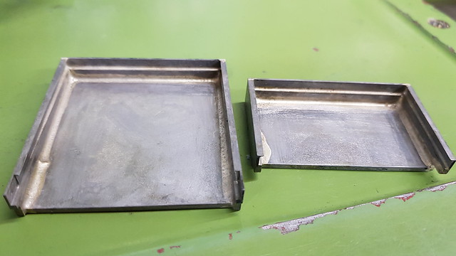 20191203_220914 20191203_220914 by Timothy Froud, on Flickr ... I haven't made any effort to clean them up at this point. Fluxing the whole assembly saves a huge amount of time and avoids losing material to oxidisation. The Silver Solder has worked its way right through the gaps so it's immensely strong.  20191203_220936 20191203_220936 by Timothy Froud, on Flickr |
|
Gary L
Elder Statesman
Posts: 1,208
|
Post by Gary L on Dec 4, 2019 0:06:51 GMT
Hi Roger It's probably me that hasn't explained well enough. It's that protruding baseplate edge that I'm querying. Check these two pre-overhaul photos from the Engine House. very clear, and no footplate edge visible, which I take to be the original condition. However other photos do show an edge, especially towards the bunker, which leads me to assume it is evidence of later patching... but I could be wrong. [photos snipped] HTH -Gary Hi Gary, Those are interesting pictures, I don't have any closeups from before the restoration. It looks like they did the bunker one way, with the edge showing and the front the other with no edge showing. It makes sense for the bunker to show all the way around since the sheet clearly protrudes at the back to hold the lamp brackets. However, that's not how 1501 is now, so I imagine the new cab was made to match the way the bunker was done without reference to how it was originally. This picture clearly shows that both the bunker and cab now have the edge of the bottom sheet visible. DSCN5664 by Roger Froud, on Flickr It's another lesson (if any were needed) in not relying on locos in preservation to get certainty about original condition. I agree that the overhauled 1501 as currrently running seems to have the cab sides sitting on a sheet throughout, but I'm pretty sure that was not the case as built, at least for the front of the cab as far back as the door; I shall be amending my Paddington drawings to suit. I can't be quite so certain about the rear portion of the cab as it merges into the bunker though. I think the footplate begins to protrude at the start of the radiused bunker corner, but it could run as far forward as the door. Any info welcomed. WRT your cab floor, the wood is looking good, albeit very 'new'. I think in real life they must have turned black all over in pretty short order. However this talk about (not) applying any treatment to the prototype cab floors shouldn't stop you doing so to your model. You are not really worried about your footplatemen slipping, but you do need to be a little protective about all the mess that gets on the cab floor when in steam. I would suggest a few coats of matt polyurethane varnish. Matt because this makes it all but invisible, but it will stop the water, paraffin etc from soaking in. Try it on a test piece first, in case you don't like it. I can't think of anything else that will protect it adequately, unless you want to try the varnish that artists use, which is very clear... again, make sure it is matt though- you can buy matting agent from the same source. HTH Gary |
|
|
|
Post by Roger on Dec 4, 2019 8:32:50 GMT
Hi Gary, Those are interesting pictures, I don't have any closeups from before the restoration. It looks like they did the bunker one way, with the edge showing and the front the other with no edge showing. It makes sense for the bunker to show all the way around since the sheet clearly protrudes at the back to hold the lamp brackets. However, that's not how 1501 is now, so I imagine the new cab was made to match the way the bunker was done without reference to how it was originally. This picture clearly shows that both the bunker and cab now have the edge of the bottom sheet visible. DSCN5664 by Roger Froud, on Flickr It's another lesson (if any were needed) in not relying on locos in preservation to get certainty about original condition. I agree that the overhauled 1501 as currrently running seems to have the cab sides sitting on a sheet throughout, but I'm pretty sure that was not the case as built, at least for the front of the cab as far back as the door; I shall be amending my Paddington drawings to suit. I can't be quite so certain about the rear portion of the cab as it merges into the bunker though. I think the footplate begins to protrude at the start of the radiused bunker corner, but it could run as far forward as the door. Any info welcomed. WRT your cab floor, the wood is looking good, albeit very 'new'. I think in real life they must have turned black all over in pretty short order. However this talk about (not) applying any treatment to the prototype cab floors shouldn't stop you doing so to your model. You are not really worried about your footplatemen slipping, but you do need to be a little protective about all the mess that gets on the cab floor when in steam. I would suggest a few coats of matt polyurethane varnish. Matt because this makes it all but invisible, but it will stop the water, paraffin etc from soaking in. Try it on a test piece first, in case you don't like it. I can't think of anything else that will protect it adequately, unless you want to try the varnish that artists use, which is very clear... again, make sure it is matt though- you can buy matting agent from the same source. HTH Gary Hi Gary, Agreed, you certainly can't be sure that what you see preserved represents the condition as new. Zooming up on your pictures again, I'm not so sure about that bottom edge detail. On the bunker, I'd say the bottom edge shows as far as the steps. On the front part of the cab, that still might be the case. If you zoom in as close as you can, you could make the case for them meeting very closely and paint masking the joint. If you look at the spectacle plate bottom and follow it round, it looks to me like it might be the same all the way round. There's a line around the bottom, but that could be paint gathering at the edge. It's really hard to be sure either way, I don't think it's as cut and dried as I first thought. It would make sense to manufacture the cab and the bunker the same way. In reality, none of these fine details are that important in my opinion. The new 1501 bunker has a different number of rivets to the old one, the chequer plate is different and this detail probably varies too. These are minor points that don't affect the overall character of the locomotive. SPEEDY doesn't even make any attempt to even get the bunker shape, the style of the rear buffer or any number of other details remotely correct, yet it's still clearly a 15xx. I think we worry too much! I just plan to Black all of the footplate parts and then brush some preservative oil over them. Coal dust and grime will just make it look authentic, I don't feel the need to clean it up to pristine condition after each run. I might add a bit more ground up Charcoal and try to work more into the wood though. The floor on 1501 is in a shocking state, I think they just run a broom round. I'm not sure what else they could really do. I still need to decide how the flooring is going to be retained. I'm toying with gluing magnets into shallow pockets in the back of each piece to they stay put but can be lifted out if necessary. They're all contained within the base tray so they can't really get free. All interesting problems to solve. |
|
Gary L
Elder Statesman
Posts: 1,208
|
Post by Gary L on Dec 4, 2019 10:52:05 GMT
It's another lesson (if any were needed) in not relying on locos in preservation to get certainty about original condition. I agree that the overhauled 1501 as currrently running seems to have the cab sides sitting on a sheet throughout, but I'm pretty sure that was not the case as built, at least for the front of the cab as far back as the door; I shall be amending my Paddington drawings to suit. I can't be quite so certain about the rear portion of the cab as it merges into the bunker though. I think the footplate begins to protrude at the start of the radiused bunker corner, but it could run as far forward as the door. Any info welcomed. WRT your cab floor, the wood is looking good, albeit very 'new'. I think in real life they must have turned black all over in pretty short order. However this talk about (not) applying any treatment to the prototype cab floors shouldn't stop you doing so to your model. You are not really worried about your footplatemen slipping, but you do need to be a little protective about all the mess that gets on the cab floor when in steam. I would suggest a few coats of matt polyurethane varnish. Matt because this makes it all but invisible, but it will stop the water, paraffin etc from soaking in. Try it on a test piece first, in case you don't like it. I can't think of anything else that will protect it adequately, unless you want to try the varnish that artists use, which is very clear... again, make sure it is matt though- you can buy matting agent from the same source. HTH Gary Hi Gary, Agreed, you certainly can't be sure that what you see preserved represents the condition as new. Zooming up on your pictures again, I'm not so sure about that bottom edge detail. On the bunker, I'd say the bottom edge shows as far as the steps. On the front part of the cab, that still might be the case. If you zoom in as close as you can, you could make the case for them meeting very closely and paint masking the joint. If you look at the spectacle plate bottom and follow it round, it looks to me like it might be the same all the way round. There's a line around the bottom, but that could be paint gathering at the edge. It's really hard to be sure either way, I don't think it's as cut and dried as I first thought. It would make sense to manufacture the cab and the bunker the same way. In reality, none of these fine details are that important in my opinion. The new 1501 bunker has a different number of rivets to the old one, the chequer plate is different and this detail probably varies too. These are minor points that don't affect the overall character of the locomotive. SPEEDY doesn't even make any attempt to even get the bunker shape, the style of the rear buffer or any number of other details remotely correct, yet it's still clearly a 15xx. I think we worry too much! I just plan to Black all of the footplate parts and then brush some preservative oil over them. Coal dust and grime will just make it look authentic, I don't feel the need to clean it up to pristine condition after each run. I might add a bit more ground up Charcoal and try to work more into the wood though. The floor on 1501 is in a shocking state, I think they just run a broom round. I'm not sure what else they could really do. I still need to decide how the flooring is going to be retained. I'm toying with gluing magnets into shallow pockets in the back of each piece to they stay put but can be lifted out if necessary. They're all contained within the base tray so they can't really get free. All interesting problems to solve. Hi Roger You are modelling 1501 as she is, not as she was, so that is all very fair. In my case I can't even take the pre-overhaul state as a guide, because bunkers were notorious for rotting, and it is likely that there had been some patching long before SVR got their hands on her. It matters because the cab-floor joint won't stay filled with paint as some have suggested, since you will inevitably need to remove the cab from time to time to gain access for repairs and mods. But you need to waterproof those thin bits of tree-wood. Wood in thin slices is very susceptible to the effects of water soaking in; it will curl, split, and the grain will rise in the blink of an eye. Not such a problem with slabs of deal in full size! Gary |
|
|
|
Post by Roger on Dec 4, 2019 11:26:11 GMT
Hi Gary, Agreed, you certainly can't be sure that what you see preserved represents the condition as new. Zooming up on your pictures again, I'm not so sure about that bottom edge detail. On the bunker, I'd say the bottom edge shows as far as the steps. On the front part of the cab, that still might be the case. If you zoom in as close as you can, you could make the case for them meeting very closely and paint masking the joint. If you look at the spectacle plate bottom and follow it round, it looks to me like it might be the same all the way round. There's a line around the bottom, but that could be paint gathering at the edge. It's really hard to be sure either way, I don't think it's as cut and dried as I first thought. It would make sense to manufacture the cab and the bunker the same way. In reality, none of these fine details are that important in my opinion. The new 1501 bunker has a different number of rivets to the old one, the chequer plate is different and this detail probably varies too. These are minor points that don't affect the overall character of the locomotive. SPEEDY doesn't even make any attempt to even get the bunker shape, the style of the rear buffer or any number of other details remotely correct, yet it's still clearly a 15xx. I think we worry too much! I just plan to Black all of the footplate parts and then brush some preservative oil over them. Coal dust and grime will just make it look authentic, I don't feel the need to clean it up to pristine condition after each run. I might add a bit more ground up Charcoal and try to work more into the wood though. The floor on 1501 is in a shocking state, I think they just run a broom round. I'm not sure what else they could really do. I still need to decide how the flooring is going to be retained. I'm toying with gluing magnets into shallow pockets in the back of each piece to they stay put but can be lifted out if necessary. They're all contained within the base tray so they can't really get free. All interesting problems to solve. Hi Roger You are modelling 1501 as she is, not as she was, so that is all very fair. In my case I can't even take the pre-overhaul state as a guide, because bunkers were notorious for rotting, and it is likely that there had been some patching long before SVR got their hands on her. It matters because the cab-floor joint won't stay filled with paint as some have suggested, since you will inevitably need to remove the cab from time to time to gain access for repairs and mods. But you need to waterproof those thin bits of tree-wood. Wood in thin slices is very susceptible to the effects of water soaking in; it will curl, split, and the grain will rise in the blink of an eye. Not such a problem with slabs of deal in full size! Gary Hi Gary, Yes, I'm modelling 1501 as she is now since I've got hundreds of photos and it's the easiest thing to do. I've spent so much time on the footplate and crawling over her, it would seem wrong to then see it as a model but not as it is today. I doubt if it's very different to how it left the factory though. If you take something like our query about the front cab edge, you have to ask yourself why that would have been changed. If any part of the original remained, they would surely have copied what was already there rather than do it differently? It's much easier just to make it the same. For things like the number and exact positions of rivets, there's no overwhelming reason to get it exactly the same though, and that's certainly the case for 1501 since I've got pictures that show differences on the bunker. I might have to soak the wood in a thinned out varnish then. The side plinths probably won't be an issue since they're 4mm thick. The ones on the floor are only 1.4mm thick though. |
|
|
|
Post by Roger on Dec 4, 2019 19:23:35 GMT
This is the Gel I bought to treat the garden furniture, so I've now added a generous helping of that to the pot of ground up Charcoal.  20191204_112815 20191204_112815 by Timothy Froud, on Flickr And this is the effect with that liberally applied and rubbed into the planking. I'll probably let that dry and then do it again. Hopefully a couple of applications of that will stop moisture from getting in and splitting the wood.  20191204_121522 20191204_121522 by Timothy Froud, on Flickr |
|
|
|
Post by delaplume on Dec 4, 2019 22:01:47 GMT
That's better !!.........very realistic, although reading the description of how you achieved the effect you are beginning to sound like an Alchemist of old !!.........."Wing of Bat", anyone ??..........LoL !!
|
|
Gary L
Elder Statesman
Posts: 1,208
|
Post by Gary L on Dec 5, 2019 0:04:20 GMT
That's better !!.........very realistic, although reading the description of how you achieved the effect you are beginning to sound like an Alchemist of old !!.........."Wing of Bat", anyone ??..........LoL !! That should do it. And yes, more realistic too, a double win! -Gary PS. When you read about how paint is made, alchemy is not far off the mark. A little more of this... a bit more of that... |
|
|
|
Post by delaplume on Dec 5, 2019 0:19:50 GMT
it's how Joyce does her cooking as well....LoL !!
|
|
|
|
Post by Roger on Dec 5, 2019 9:51:27 GMT
|
|
|
|
Post by Cro on Dec 5, 2019 11:29:33 GMT
Ouch...?!
|
|


