Haymes
Active Member

Posts: 29
|
Post by Haymes on Jan 11, 2020 10:11:34 GMT
Yes correct on the above.The weights (there is a dedicated pair for each engine) are hanged on the chains in order to back fill the boiler and also as frost protection if the engine is left to go cold during winter months because with the spring loaded valves open, the injectors and pipework are drained.
Regards,
Carl
|
|
|
|
Post by Roger on Jan 11, 2020 22:02:19 GMT
Although I'd added all of the hand rails to the bunker, I hadn't even made them for the cab. It's odd because I found one of the rods shown but had to make the other. Maybe I just ran out of Silver Steel and ordered some more, I have no idea. Anyway, the former was already made because this is the hand rail on the boiler side of the cab entrance, so this is the same as the one on the bunker.  20200111_205334 20200111_205334 by The train Man, on Flickr I've nipped this lightly against a piece of scrap slightly proud of the vise jaws so I can measure this distance at both ends and get the rod in the middle.  20200111_213140 20200111_213140 by The train Man, on Flickr I used a couple of small toolmaker's clamps to hand it over and move it to the other end without disturbing it.  20200111_213451 20200111_213451 by The train Man, on Flickr The groove in the former is slightly shallower than the diameter of the rod so it's gripped by the vice. The ends are slightly over 90 degrees so I can get a full bend with a little spring back. I think I've allowed a couple of degrees for that.  20200111_213540 20200111_213540 by The train Man, on Flickr Anyway, here they are, and they fit the holes nicely.  20200111_213916 20200111_213916 by The train Man, on Flickr This is the angle to the front of the side opening, it's used to support the side panel of the cab and has a slot for the door latch. Here I'm machining it to the right width as it was slightly too wide.  20200111_104833 20200111_104833 by The train Man, on Flickr The bottom edge needs to clear the angle on the base plate. 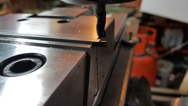 20200111_113614 20200111_113614 by The train Man, on Flickr Here's a quick sanity check to make sure it's all going to fit.  20200111_164721 20200111_164721 by The train Man, on Flickr The door latch was machined with a 1mm PCB 2-flute sloping in at 2 degrees and taking 0.03mm deep cuts. That took half an hour, but I did both sides without breaking the cutter.  20200111_185820 20200111_185820 by The train Man, on Flickr It didn't go quite through, so that had to be finished with needle files. The ends had to be squared up anyway.  20200111_190357 20200111_190357 by The train Man, on Flickr The angles aren't riveted in place yet, but I've painted the mating faces with Fertan and I'll rivet them on next.  20200111_192423 20200111_192423 by The train Man, on Flickr |
|
|
|
Post by delaplume on Jan 12, 2020 12:02:53 GMT
Nice to see you getting to grips with those handrails, Roger ----LoL !!
|
|
uuu
Elder Statesman
 your message here...
Posts: 2,812
|
Post by uuu on Jan 12, 2020 12:17:56 GMT
Which Fertan product do you use for this Roger, please? Is it the "rust converter" or the "rust remover"?
Wilf
|
|
|
|
Post by Roger on Jan 12, 2020 22:37:18 GMT
Hi Wilf, the Fertan product I use just claims "... is the optimal treatment for the removal of rust from all metal constructions". It's pretty watery and takes a while to take on that really dark brown hue. When you first apply it to shiny clean Steel, it doens't look like it will do anything. It claims that it's better than shot blasting when preparing for painting. I seem to have spent an awful lot of time with very little to show for it. The angles for the doors to latch onto have both been riveted in place and the outside of the rivets filed flush. I've also added the handle on the left and on the far side. I've bonded those in with permanent high strength Loctite. I've also cut the formed cab edging on this side and riveted it in place with 0.5mm rivets, again filing off the rivets. They ought to show really, but being Brass they're so soft that they deform too easily to make a neat job. I couldn't get any 0.5mm Steel rivets. If I'd been able to source those, I'd have made them visible on the outside. The inside looks ok, so if they all come out like that I'll leave them to show on the inside. They're pretty small so I don't mind if they show or not. I've almost run out of 0.5mm rivets now, so I've ordered a load more to finish this off. There's the matching piece to be fitted on the lower part of the cab, and also one to the RH side of the door down the side of the bunker. 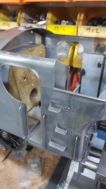 20200112_222136 20200112_222136 by The train Man, on Flickr |
|
|
|
Post by mugbuilder on Jan 12, 2020 23:57:36 GMT
Fabulous work Roger.
That engine will be too good to use.
|
|
|
|
Post by Roger on Jan 13, 2020 6:21:55 GMT
Fabulous work Roger. That engine will be too good to use. Thanks for your kind words, but it's very much a working locomotive to be used and enjoyed. If it was going to be just for exhibition purposes, I'd have taken a lot more trouble over it. |
|
|
|
Post by simplyloco on Jan 13, 2020 8:56:38 GMT
Fabulous work Roger. That engine will be too good to use. SNIP If it was going to be just for exhibition purposes, I'd have taken a lot more trouble over it. I wouldn't have thought that was possible...! |
|
|
|
Post by 92220 on Jan 13, 2020 9:13:52 GMT
+1. !!!!!
|
|
|
|
Post by ilvaporista on Jan 13, 2020 10:13:31 GMT
Fabulous work Roger. That engine will be too good to use. Thanks for your kind words, but it's very much a working locomotive to be used and enjoyed. If it was going to be just for exhibition purposes, I'd have taken a lot more trouble over it. Yes I was thinking only the other day how little effort you were putting in to this loco..... I dread to think what it would look like if you had 'taken the trouble'. I think us lesser mortals might have taken up pottery.. |
|
|
|
Post by simplyloco on Jan 13, 2020 12:07:06 GMT
Thanks for your kind words, but it's very much a working locomotive to be used and enjoyed. If it was going to be just for exhibition purposes, I'd have taken a lot more trouble over it. Yes I was thinking only the other day how little effort you were putting in to this loco..... I dread to think what it would look like if you had 'taken the trouble'. I think us lesser mortals might have taken up pottery.. On the other hand, it wouldn't surprise me if Roger slept under his bed: he has to be a little potty...  |
|
|
|
Post by ettingtonliam on Jan 13, 2020 14:02:11 GMT
Roger probably gets a higher level of accuracy, especially in things like riveting, than Swindon did in the first place. How he could possibly take more care is beyond my belief! I just hope all those tiny rivet heads still show after painting.
At least with my prototype (Locomotion) if anyone criticises my riveting (and they will) I can point them to the original, and claim (justifiably) how alike they are.
|
|
|
|
Post by andyhigham on Jan 13, 2020 14:13:25 GMT
When we are modelling a standard gauge loco in 5" we need to be about 12 x more accurate. For example if a rivet on a full size is 3mm out of line it is barely noticeable, in our scale it would stand out like a bulldogs bo**ocks
|
|
|
|
Post by delaplume on Jan 13, 2020 21:26:35 GMT
Maybe his middle name is}--- Guzunder ??
|
|
|
|
Post by Roger on Jan 13, 2020 22:19:33 GMT
This is the RH side getting the beading added to the cab side. I finally found the tiny 'G' clamps I made for the bunker so this side was easier to fit. Sadly, the 0.5mm HSS drills I had were junk, each one barely did one hole before it was blunt, so they got binned and two lots of 10 were ordered from two different suppliers on eBay for very little. I'll see if they are actually made from HSS instead of cheese this time.  20200113_152011 20200113_152011 by The train Man, on Flickr Even so, I managed to do nearly half of them. I've also run out of rivets, so I'm a bit stuck on this for the moment.  20200113_152029 20200113_152029 by The train Man, on Flickr I realised that I hadn't made the large radius inner former for doing the lower beading. Actually, I only realised that when I bent the first one and realised it was miles too tight and that the radius was different! Oops! I've found the 3D model for the other former now, so that needs making and the other two parts making. The final two pieces are straight. |
|
|
|
Post by karel52 on Jan 14, 2020 2:02:00 GMT
Hello Roger,
My first post. I have read your thread from the start. Your initial aims as I understand it was simply to come to grips with the valve motion on Speedy. This has turned into a masterful engineering project that I will say for I think all of us we would be proud to do the same. I realize you have considerable skill in machining from other endeavors but after all this is your first engine. To top it off you have so generously taken the time to show how you have done it. I thank you greatly for that. My only regret is that now I have caught up in the thread I will like everyone else be sitting on the edge of my chair waiting for the next chapter of your saga..
Happy building
Karel
|
|
|
|
Post by Roger on Jan 14, 2020 9:35:44 GMT
Hello Roger, My first post. I have read your thread from the start. Your initial aims as I understand it was simply to come to grips with the valve motion on Speedy. This has turned into a masterful engineering project that I will say for I think all of us we would be proud to do the same. I realize you have considerable skill in machining from other endeavors but after all this is your first engine. To top it off you have so generously taken the time to show how you have done it. I thank you greatly for that. My only regret is that now I have caught up in the thread I will like everyone else be sitting on the edge of my chair waiting for the next chapter of your saga.. Happy building Karel Hi Karel, Thanks for kind comment. I often wonder who, if any, outside of the small circle of regular followers is quietly following along. I'm glad you find it interesting and perhaps useful. As you rightly point out, the aims of the build have changed somewhat, but very much to the benefit of the end result. The feedback and generous sharing of the folk here have made this possible, it wouldn't have happened without you all. |
|
|
|
Post by Roger on Jan 16, 2020 22:10:50 GMT
The beading on the edge of the Cab needs bending to a different radius, and until now I haven't bothered to make a mandrel to make holding and adjusting these easy. So I'm rectifying that here.  20200116_122124 20200116_122124 by The train Man, on Flickr This is the new former in question, with the 8mm diameter form tool that I used to get the required profile.  20200116_162750 20200116_162750 by The train Man, on Flickr It's too big to fit my usual bender base, but this other one uses the same diameter pin holes so I pressed that into service.  20200116_113806 20200116_113806 by The train Man, on Flickr  20200116_113825 20200116_113825 by The train Man, on Flickr  20200116_113913 20200116_113913 by The train Man, on Flickr Again, the little G-clamps made life easier.  20200116_211850 20200116_211850 by The train Man, on Flickr Both sets of 0.5mm drills have arrived and they're both garbage, so I've had to set it up a bit better on the mill so I can use a Carbide PCB drill without breaking it. This still needs the ends trimming and the rivets filing flush, but it's firmly in place.  20200116_215822 20200116_215822 by The train Man, on Flickr |
|
|
|
Post by 92220 on Jan 17, 2020 8:51:33 GMT
Nice one Roger! That mini bender of yours must be so useful. It is so simple too, but capable of bending round AND L and T shaped strip. I must get one made!!!!
Bob.
|
|
|
|
Post by simplyloco on Jan 17, 2020 8:58:54 GMT
Nice one Roger! That mini bender of yours must be so useful. It is so simple too, but capable of bending round AND L and T shaped strip. I must get one made!!!! Bob. Agreed. I'm delighted that Roger has been able to make some improvements to my original design!  John |
|


