|
|
Post by Rob on Oct 22, 2018 23:39:55 GMT
Thanks Lisa, that does help to confirm the full size practice! Bob, the one part I find odd is that BR chose to retain so many of the GWR design features - why didn't they make it simpler for themselves and pinch some of the standard designs? One of those design quirks is what I've been working on a design for the past few nights - the fish belly coupling rods. The rods as drawn are far, far too big and absolutely nothing like the real thing. So I've been attempting to recreate these in a 3D model so I can work out the relevant sizes and I can in turn make up the crank pins. What a pain that was - I think I discovered several bugs in my modelling software drawing these up. To make these to scale, they end up being very thin - I worry these may now not be strong enough. The thickness of the main body of the rod goes from 0.250" to 0.175" for example. These are the 3D renderings - the fish belly is drawn entirely by eye as I haven't got any dimensions to work from. I hope it has more than a passing resemblance to the real thing! 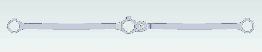 Fishbelly Coupling Rods Side on Fishbelly Coupling Rods Side on, on Flickr 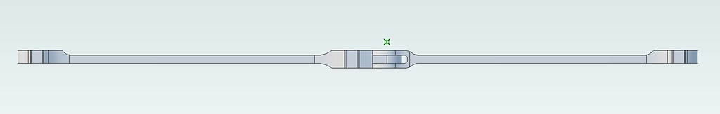 Fishbelly Coupling Rods Top Down Fishbelly Coupling Rods Top Down, on Flickr 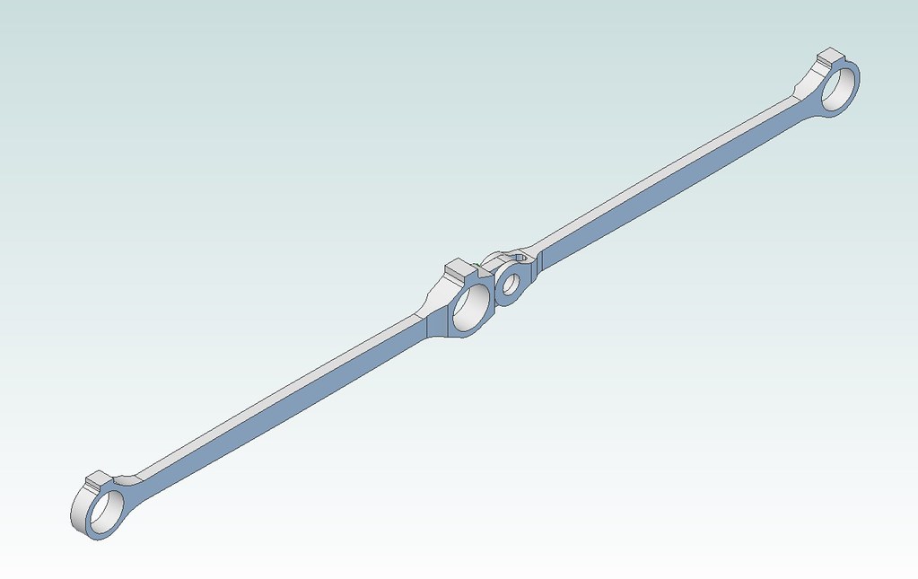 Fishbelly Coupling Rods Fishbelly Coupling Rods, on Flickr What is everyone's thoughts, both on appearance and whether or not they'll be strong enough for the job? |
|
|
|
Post by Roger on Oct 23, 2018 7:42:19 GMT
Hi Rob,
They look fine to me, the only thing you might want to do is to hide the knuckle screw. I made up a dummy head for the bolt so it could still be a large size but had the illusion of being like the full sized one. I think they will be plenty strong enough.
|
|
|
|
Post by 92220 on Oct 23, 2018 8:26:14 GMT
Hi Rob.
As Roger says, they should be strong enough. If you are still a bit concerned, you can always machine them from EN24T which in the T state, I think is 44 tonne tensile as opposed to EN1A at around less than half that.
Bob.
|
|
|
|
Post by simplyloco on Oct 23, 2018 8:50:46 GMT
Hi Rob. As Roger says, they should be strong enough. If you are still a bit concerned, you can always machine them from EN24T which in the T state, I think is 44 tonne tensile as opposed to EN1A at around less than half that. Bob. Hi Bob I think it would be a bit tough for us mere mortals. I once had to machine a load of 2" x 24" bars in EN25Y, a much stronger material, and that was 'difficult' to say the least! John |
|
|
|
Post by 92220 on Oct 23, 2018 13:08:25 GMT
Hi John.
Actually EN24T is not bad for machining, especially if you use carbide tools, though I have machined it quite satisfactorily with HSS. Rotation just has to be about 25% slower than for carbide. I bought a piece of 1" diam EN24T because, at the time, I couldn't buy flat the size I wanted, and I machined my draw hooks out of it. That was a lot of milling but I never had a problem and I used HSS cutters. It is actually much easier to machine than silver steel/gauge plate; and it has the advantage that with careful heat treatment, the tensile strength can be brought up to 100T.
Bob.
|
|
|
|
Post by Rob on Oct 25, 2018 21:25:35 GMT
Hi Rob, They look fine to me, the only thing you might want to do is to hide the knuckle screw. I made up a dummy head for the bolt so it could still be a large size but had the illusion of being like the full sized one. I think they will be plenty strong enough. I have a design in mind for that screw - an interlocking pin with a small headed bolt through the middle. The bolt can be to scale as it only has to retain the pin, the pin itself takes all of the load. Hi Rob. As Roger says, they should be strong enough. If you are still a bit concerned, you can always machine them from EN24T which in the T state, I think is 44 tonne tensile as opposed to EN1A at around less than half that. Bob. Bob, what size cross section would be used to measure that tensile strength? I believe the cold rolled I have is EN1A, I'm inclined to go for it! |
|
|
|
Post by Rob on Oct 25, 2018 21:45:08 GMT
This update is only a quick one - nothing too interesting to report. I drilled the oil feed holes in the eccentric straps, and started the filing and sanding process on the OD. 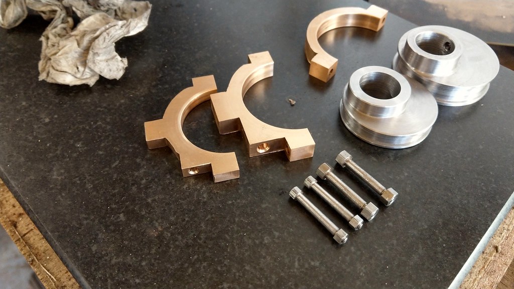 2018-10-25_09-55-58 2018-10-25_09-55-58, on Flickr 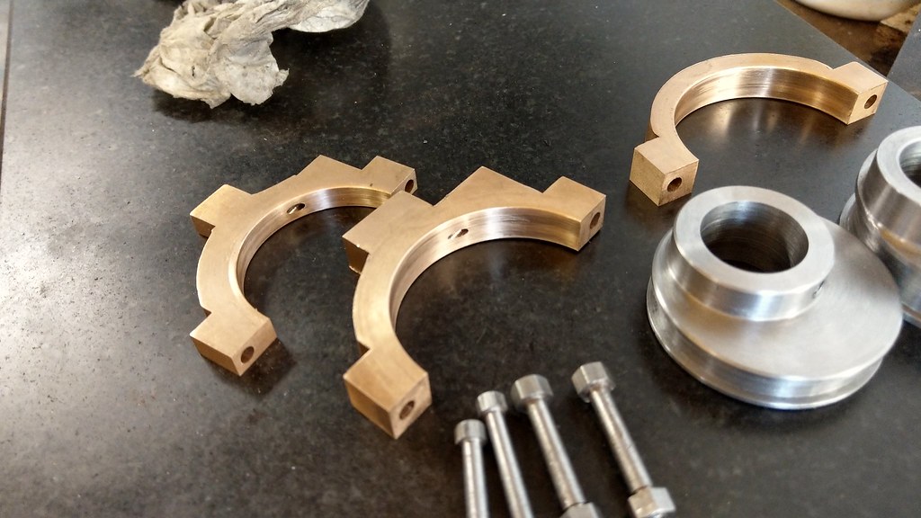 2018-10-25_09-57-28 2018-10-25_09-57-28, on Flickr 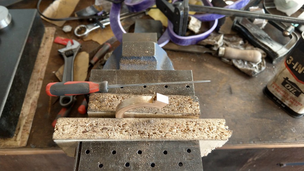 2018-10-25_09-59-55 2018-10-25_09-59-55, on Flickr And here is a comparison of the LBSC coupling rods: 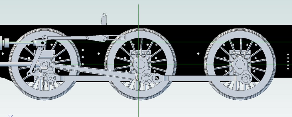 RodComparison1 RodComparison1, on Flickr And the Rob GWR variety: 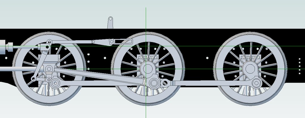 RodComparison2 RodComparison2, on Flickr They're a lot slimmer in almost every respect. The only dimensions that remain the same are the width of the driving pin boss, the ID of the the bosses and the ID and OD of the bushes. Even the front and rear bushes become thinner! Now I just need to work out how best to make them. I'd love to have a bash at manual numerical control, but I may just end up making filling buttons and doing it the old fashioned way. I have ordered a set of centre pitch calipers from Machine DRO to measure the distance between axles accurately. I'll also attempt to normalise the cold rolled steel I have. Thinking of using a charcoal fire with the vacuum as a blower as I don't think my propane torch has the output to heat all of that steel at once. |
|
|
|
Post by Roger on Oct 25, 2018 22:00:01 GMT
Hi Rob,
I'd certainly recommend the method that Pault posted for making the rods. The key thing that really helps is being able to hold the rods completely clear of the vice so you can machine the sides in one setup. It also gives you something to clamp down to hold it the other way to machine the profile.
Obviously there are many ways to go about this, and that method particularly suits CNC. but I also think it's a very good way to hold the parts using manual methods too.
The connecting rods are a bit more tricky because of the flutes, but the main shape can be done the same way as the coupling rods.
|
|
stevep
Elder Statesman

Posts: 1,070
|
Post by stevep on Oct 26, 2018 8:24:51 GMT
Rob, Hand filing the outside of the eccentric straps is hard work. When I did mine, I mounted the straps (after I had joined on the rods, and before profiling) on my small rotary table (GH Thomas design) using the spare concentric eccentric I made for the strap assembly jig. Did most of the shape with a mill, and just had to clean up the ends. 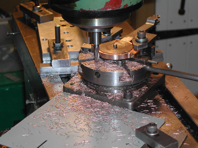 You will notice in the background a large aluminium angle. This was the stop to prevent over rotation. Of course, with a geared table, that wouldn't have been necessary. |
|
|
|
Post by Rex Hanman on Oct 26, 2018 8:49:15 GMT
This was the stop to prevent over rotation. Of course, with a geared table, that wouldn't have been necessary. Steve, even with my geared table I still set up a stop. It's quite easy to go that little bit too far! It saves having to constantly peer at the scale too, just rotate between the two limits. |
|
|
|
Post by Rob on Oct 26, 2018 9:31:11 GMT
Hi Rob, I'd certainly recommend the method that Pault posted for making the rods. The key thing that really helps is being able to hold the rods completely clear of the vice so you can machine the sides in one setup. It also gives you something to clamp down to hold it the other way to machine the profile. Obviously there are many ways to go about this, and that method particularly suits CNC. but I also think it's a very good way to hold the parts using manual methods too. The connecting rods are a bit more tricky because of the flutes, but the main shape can be done the same way as the coupling rods. I'm not sure if I'm familiar with Pault's method - but it sounds similar to what I was thinking. I ordered my BMS half an inch over size to give me plenty of metal to clamp in the vice. I still need to revise the design of the connecting rods - they're currently still drawn to LBSC's design and now do not suit the new coupling rods. Rob, Hand filing the outside of the eccentric straps is hard work. When I did mine, I mounted the straps (after I had joined on the rods, and before profiling) on my small rotary table (GH Thomas design) using the spare concentric eccentric I made for the strap assembly jig. Did most of the shape with a mill, and just had to clean up the ends. You will notice in the background a large aluminium angle. This was the stop to prevent over rotation. Of course, with a geared table, that wouldn't have been necessary. Steve, your method does look much easier, and accurate! I don't yet have a rotary table, but it is an essential purchase I think. Your method could be used for the coupling rod ends, too. |
|
|
|
Post by Deleted on Oct 26, 2018 9:46:52 GMT
Hi Rob
You may find how I held my rods of some help, details start on page 109. Ok, I started with laser cut blanks to save time but I would use the same jig/process if machining from stock..
regards
Pete
|
|
stevep
Elder Statesman
Posts: 1,070
|
Post by stevep on Oct 26, 2018 12:06:19 GMT
Hi Rob, Clip I don't yet have a rotary table, but it is an essential purchase I think. Your method could be used for the coupling rod ends, too. Rob, I find my rotary table invaluable. It is worth a small diversion/delay on the engine to get a set of castings (available from several sources) and make one. 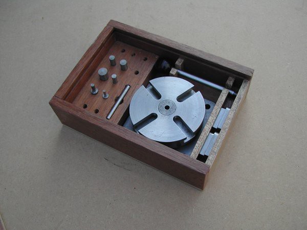 I also made some T-nuts to fit the table (with rounded ends to fit tight into the end of the slot - which I machined actually using the table), and various mandrels of various diameters, so I can either mount things directly on the table using one of them, or to mount a larger mandrel. I then made a box to keep all the bits together. |
|
|
|
Post by Rob on Oct 26, 2018 15:08:22 GMT
Hi Rob You may find how I held my rods of some help, details start on page 109. Ok, I started with laser cut blanks to save time but I would use the same jig/process if machining from stock.. regards Pete Pete, I've had a quick look at your thread and it will definitely help. I'll have a more thorough look later. Another vote for the rotary table! Rob, I find my rotary table invaluable. It is worth a small diversion/delay on the engine to get a set of castings (available from several sources) and make one. I also made some T-nuts to fit the table (with rounded ends to fit tight into the end of the slot - which I machined actually using the table), and various mandrels of various diameters, so I can either mount things directly on the table using one of them, or to mount a larger mandrel. I then made a box to keep all the bits together. Steve, looks like a thorough job. Even the box to store it in! I'm not sure I have the patience to make my own. I had been wondering whether I should go for a rotary table or a dividing head. A dividing head is quite a bit more chunky (and expensive!) but can you do everything you can do on a rotary table on a dividing head? Is it worth the additional cost? The Machine DRO centre pitch calipers arrived today. Little disappointed they don't appear to have a way to zero them accurately, unless I'm missing something. You can zero them with the legs touching, but obviously there's still a gap at the pointy end when you do that. The only way I can see to use them is to measure the size of one of the legs, and then add that dimension to the reading you get. No big hardship, but just a bit of a pain as it's not a nice round number - 0.3935"! When comparing my axle centres one side of the loco to the other, the driving and trailing axles appear to be within a thou of each other, and one thou to size as per the drawings - top job. The driving and front axle seem to have a discrepancy of 4-5 thou one side to the other, not so great. I'm wondering whether I should attempt to correct that. I might try re-erecting the frames with the guide bars in place as I did disturb it recently to de-rust parts after it sitting for a year or two, but that seems unlikely to fix the problem if the driving and trailing axles are currently almost spot on. |
|
don9f
Statesman
 Les Warnett 9F, Martin Evans “Jinty”, a part built “Austin 7” and now a part built Springbok B1.
Posts: 960 
|
Post by don9f on Oct 26, 2018 18:29:34 GMT
Hi Rob if it’s any help to you, I don’t have a dividing head and have never actually used one. I do however have a 6 inch rotary table and wouldn’t be without it! It has served me well but it only holds a chuck (100mm dia) via a No2 Morse Taper adapter so it’s not that rigid. You just have to be careful that’s all.
Is the discrepancy you have with axle centres due to the leading axleboxes being machined slightly differently....ie the axle hole position relative to the horn faces?
Cheers Don
|
|
|
|
Post by Rob on Oct 26, 2018 21:58:20 GMT
Don, I'm really not sure. When boring them, I did check the position of the bore to make sure they were exactly central. And the axle does turn freely.
The horn faces were machined back to back so should be identical.
More investigation required I think.
|
|
davidk
Active Member

Posts: 32
|
Post by davidk on Oct 27, 2018 7:36:10 GMT
Hi Rob
On the Machine DRO website they quote the width of the legs: 10mm (0.3937")
Pity they don't seem to do a version with 1/2" width legs or similar!
Regards
David
|
|
|
|
Post by Roger on Oct 27, 2018 7:46:56 GMT
Don, I'm really not sure. When boring them, I did check the position of the bore to make sure they were exactly central. And the axle does turn freely. The horn faces were machined back to back so should be identical. More investigation required I think. Absolutely, measure and then measure again. I had a problem with one of the crank pins being at a slightly different radius to the others (I should have made a drill/reaming jig) and that took a lot of measurements to figure out what was to blame. Assume nothing, not even when you've machined things back to back. I'd check everything. Just a thought... you haven't installed one of the axleboxes the wrong way round? If the hole for the axle isn't perfectly central then that would put the axle at an angle. |
|
|
|
Post by Rob on Oct 27, 2018 9:32:55 GMT
Hi Rob On the Machine DRO website they quote the width of the legs: 10mm (0.3937") Pity they don't seem to do a version with 1/2" width legs or similar! Regards David David, you're right. They do, plain as day. I guess I just didn't notice, perhaps because it's written in metric! Absolutely, measure and then measure again. I had a problem with one of the crank pins being at a slightly different radius to the others (I should have made a drill/reaming jig) and that took a lot of measurements to figure out what was to blame. Assume nothing, not even when you've machined things back to back. I'd check everything. Just a thought... you haven't installed one of the axleboxes the wrong way round? If the hole for the axle isn't perfectly central then that would put the axle at an angle. The axleboxes were handed with the outside edge thicker than the inside edge, I believe to adjust the gauge to meet GL5 standards, so they should be installed the right way around. I'll definitely check that too though. I hope it's something simple, these backwards steps are enough to dampen your enthusiasm. |
|
don9f
Statesman
Les Warnett 9F, Martin Evans “Jinty”, a part built “Austin 7” and now a part built Springbok B1.
Posts: 960
|
Post by don9f on Oct 27, 2018 20:09:07 GMT
Hi Rob, what longitudinal clearance is there between the axle box horn faces and the horn guides? Maybe one solution is to “adjust” the clearance of one or both of the leading axle boxes so the leading axle can become more parallel to the driving axle....
On the other hand, annoying though it might be and I know how I would feel, I don’t think the 4-5 thou discrepancy is going to be a real problem. The length of the relevant section of the coupling rod could simply be adjusted to suit.
Cheers Don
|
|


