|
|
Post by Rob on Oct 27, 2018 21:20:41 GMT
Hi Rob, what longitudinal clearance is there between the axle box horn faces and the horn guides? Maybe one solution is to “adjust” the clearance of one or both of the leading axle boxes so the leading axle can become more parallel to the driving axle.... On the other hand, annoying though it might be and I know how I would feel, I don’t think the 4-5 thou discrepancy is going to be a real problem. The length of the relevant section of the coupling rod could simply be adjusted to suit. Cheers Don Don, I did consider that, much as I'd hate to shim it one way or another. And conversely making the rods individually would mean I couldn't do them back to back at the same time. That being said, I do have some good news. I decided to take things apart to measure everything. Thankfully, the horn faces are spot on. 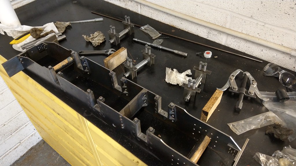 IMAG1615 IMAG1615, on Flickr The bores are in the same place in both boxes, however it seems that I may have taken a thou or two off one face of one box when I was fitting it to the horns. I know the bore is in the right place as the opposite face measurement matches the other box, if that makes sense. Effectively, the box is a thou or two too small on one side only. That thou or two can't explain the 4-5 thou discrepancy, even with sine error. So I decided to break out the frame erecting kit again - the guide bars and spacer tubes. 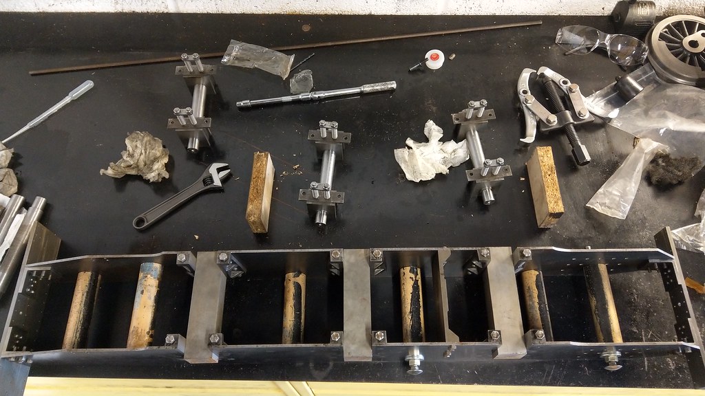 IMAG1616 IMAG1616, on Flickr 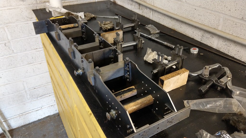 IMAG1617 IMAG1617, on Flickr I originally set the frame up on the milling machine bed, but I currently have the vice set up and didn't want to disturb it. My rather smaller granite surface plate made do. I slackened off all of the bolts on the stretchers and the buffer beams, then clamped the frames with the spacer tubes and guide bars in place, before re-tightening everything. When measuring again, my driving and trailing axles now seem to be between dead on and a thou out - repeatability is a struggle - and the driving and leading between a thou and 2 thou. Less than half the original error seems to be a good improvement. I think I can live with that! |
|
don9f
Statesman
 Les Warnett 9F, Martin Evans “Jinty”, a part built “Austin 7” and now a part built Springbok B1.
Posts: 960 
|
Post by don9f on Oct 27, 2018 22:27:19 GMT
Well done for making that improvement....I’ve just been scanning through the thread from page 1 and read about your horn guide & axlebox machining around pages 6 & 7....about 4 years ago!
Cheers Don
|
|
|
|
Post by Rob on Oct 28, 2018 10:25:10 GMT
It has been slow going! I looked back at the start of the thread, and it seems I may have started this in 09/10. I hadn't realised it had been almost 9 or 10 years already. Oh dear. Will I even be finished before I am allowed to retire in 50 years time?
I also seem to have far fewer photographs posted than I thought. I know I took a bunch of pictures machining the horns, but I seem to have only one showing the initial clamping set up.
|
|
stevep
Elder Statesman

Posts: 1,070
|
GWR 15xx
Oct 28, 2018 13:25:19 GMT
via mobile
Post by stevep on Oct 28, 2018 13:25:19 GMT
Remember that you need to leave room for the oil, and also clearance for suspension movement - so a couple of thou is not a problem.
|
|
dc309
Seasoned Member

Posts: 146
|
GWR 15xx
Oct 28, 2018 21:31:12 GMT
via mobile
Post by dc309 on Oct 28, 2018 21:31:12 GMT
Looking good Rob!
|
|
|
|
Post by Rob on Oct 28, 2018 22:34:09 GMT
Steve, I hope so. As always, I'm concerned about all the tolerances adding up. Thanks Dan! Any progress on your rods? This afternoon I was concentrating on the trailing crank pins. I decided to use ground silver steel as recommended by LBSC. This presented a problem in that I had to have the main bearing journal running true. My three jaw repeats between 1 and 2 thou, which I think is good - but not good enough. So the 4 jaw was the only option. The problem is that 7/16 is right on the minimum size limit for my 4 jaw, so I could only turn the part that fits into the wheel boss. When swapping ends to form the threads, the 3 jaw would have to do. 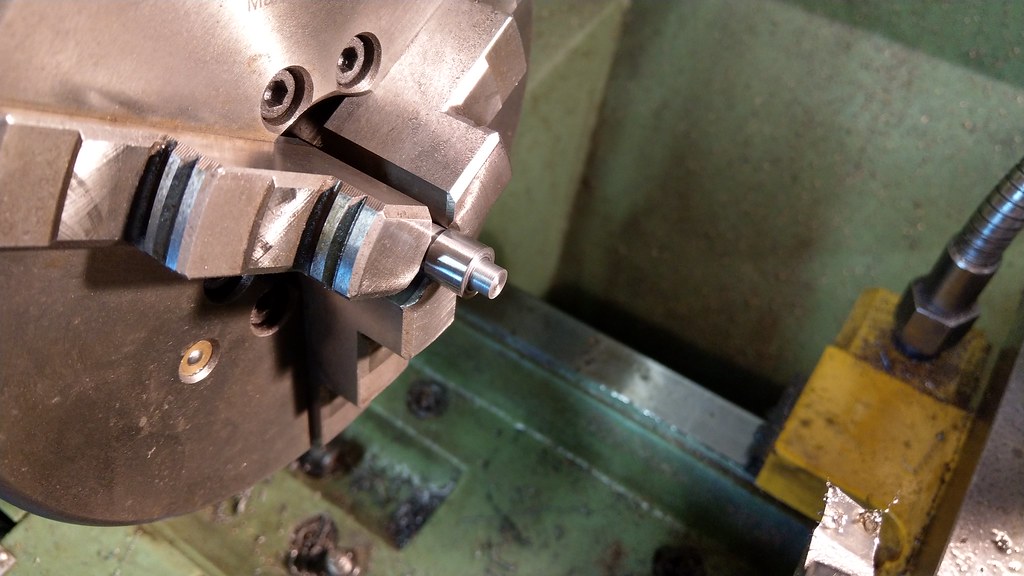 IMAG1619 IMAG1619, on Flickr This leads me on to a complaint of mine regarding split dies. Why is there so much clearance between the edge of the die and the thread forming teeth? Some clearance is necessary - but when it's almost a quarter of the die I find it very frustrating. Because of this, I needed an enormous amount of relief behind the threads. 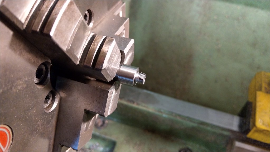 IMAG1620 IMAG1620, on Flickr I remember my father telling me years ago that only 3 (I think) threads are in use at any one point - but in my pins I'm left with 4 threads total. Hopefully that will be enough. 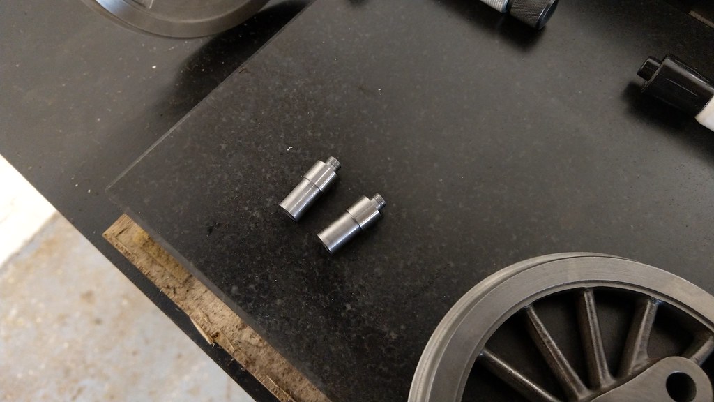 IMAG1621 IMAG1621, on Flickr Couldn't resist trying them out in one of my surplus axles. 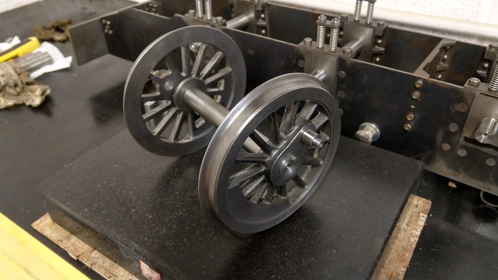 IMAG1623 IMAG1623, on Flickr I made them a push fit into the wheel boss, I'll loctite them once I've made the couplings rods and everything fits as it should. |
|
don9f
Statesman
Les Warnett 9F, Martin Evans “Jinty”, a part built “Austin 7” and now a part built Springbok B1.
Posts: 960
|
Post by don9f on Oct 29, 2018 20:11:11 GMT
Hi Rob, having formed a thread, I sometimes turn the die round and run it on “back to front” as it can often cut a little closer to a shoulder (depends of course on how the die has been made).
Another idea.....instead of cutting a relief groove in the crankpin, you could machine away the first thread or two in the backside of the nut so it doesn’t interfere with the unthreaded bit near the shoulder. Presumably the nuts have integral washers?
In any event, I’d be happy with four threads in this situation....
Cheers Don
|
|
|
|
GWR 15xx
Oct 29, 2018 20:49:24 GMT
via mobile
Post by Roger on Oct 29, 2018 20:49:24 GMT
Hi Rob,
Why not screw cut the threads, you can make the relief much smaller if you do that.
|
|
|
|
Post by Rob on Oct 29, 2018 21:51:03 GMT
Hi Rob, having formed a thread, I sometimes turn the die round and run it on “back to front” as it can often cut a little closer to a shoulder (depends of course on how the die has been made). Another idea.....instead of cutting a relief groove in the crankpin, you could machine away the first thread or two in the backside of the nut so it doesn’t interfere with the unthreaded bit near the shoulder. Presumably the nuts have integral washers? In any event, I’d be happy with four threads in this situation.... Cheers Don Don, I did try that, but this particular die is much the same both sides. I also considered relieving the nut - I was originally intending to do this with a simple chamfer, but when I saw the extent needed I decided it was an easier operation to relieve the pin instead rather than attempting to chuck the thin nut/make a fixture. Hi Rob, Why not screw cut the threads, you can make the relief much smaller if you do that. I thought I couldn't cut 40 TPI Roger, but now I look at Warco's website it suggests I can. Either way, I don't have a 55 degree tool. Excuses, excuses! I could have gone metric too, but I think I'd have gone with an M6 fine thread and I don't have a any fine taps. |
|
|
|
Post by Roger on Oct 29, 2018 22:26:36 GMT
Hi Rob, Why not screw cut the threads, you can make the relief much smaller if you do that. I thought I couldn't cut 40 TPI Roger, but now I look at Warco's website it suggests I can. Either way, I don't have a 55 degree tool. Excuses, excuses! I could have gone metric too, but I think I'd have gone with an M6 fine thread and I don't have a any fine taps. Fair enough, although you can always grind up a tool. I almost exclusively use Carbide inserts for all my thread cutting these days because you get the right form for the whole thread. You do need to stock one for each pitch though, so it's not cheap to get started. At least with Metric threads you can often use an insert from the Coarse threads to cut a Fine thread of the same pitch. |
|
|
|
Post by Rob on Oct 30, 2018 22:12:58 GMT
In order to make the driving crank pin I need to make some decisions about the return crank. The return crank as drawn is nothing like the real thing, so I wanted to change the way it looked. I've seen a number of different ways of doing this. This is a draft of my interpretation: 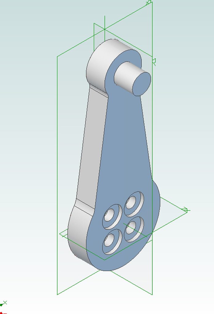 ReturnCrankFront ReturnCrankFront, on Flickr 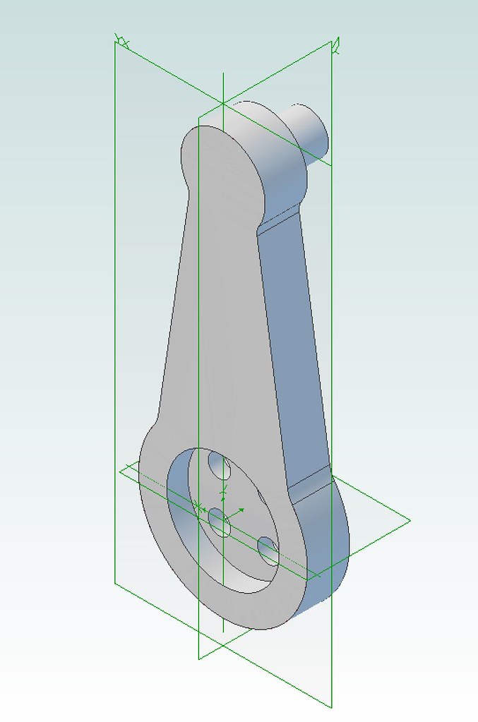 ReturnCrankBack ReturnCrankBack, on Flickr This would also simplify the driving crank pin in that the outside shoulder would be made redundant - the full diameter of the 1/2" pin would fit into the back of the return crank. I was wondering whether the four bolts would be strong enough, but surely 4 7BA bolts are enough for the rotational forces the crank would experience? You could strengthen the joint with loctite, too. As far as the write up goes, it seems the done thing is to determine the position of the return crank after everything else has been made and assembled - is this still the current wisdom? If you know where the return crank should be, why can't you set it beforehand? |
|
|
|
GWR 15xx
Oct 30, 2018 22:40:42 GMT
via mobile
Post by Roger on Oct 30, 2018 22:40:42 GMT
I agree that you can set the return crank angle precisely beforehand. I think you will need those bolts to have no thread where they cross the joint else there is likely to be some movement.
Another thought would be too machine a slot and have flats on the pin.
One last cosmetic detail, the bottom edge of the crank has a curve on the bottom face. If you look at the pictures of 1501 you'll see what I mean.
|
|
|
|
Post by Rob on Oct 31, 2018 21:49:51 GMT
Now I just need to work out exactly how to set it before hand, and indeed find out what it should actually be set to! The drawings do not have any of these details.
I think you're right about the movement on the threads. I had thought about fitted pins with reamed holes, but the more I think about it the more a tongue and groove solution appeals. I think this is how it would be done in full size - a groove machined in the crank pin and a tongue on the return crank.
For me, I think it would be easier to machine this in reverse - machine a groove in the return crank and machine the tongue on the return crank - as I can't see an easy way to machine the recess in the return crank for the pin to fit into and include a tongue at the same time, at least not with my manual machines.
Alternatively, two grooves in both the crank and pin, and a bit of keystock that fits between the two.
This is just a rough mock up Roger, I haven't put in the cosmetic details just yet. I think the other end of the crank is also curved on the opposite face too.
|
|
|
|
Post by Rob on Oct 31, 2018 23:43:13 GMT
To put my thoughts into 3D: 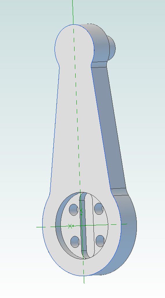 ReturnCrankBackGroove ReturnCrankBackGroove, on Flickr 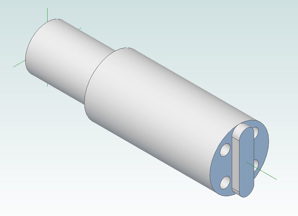 DrivingCrankPin DrivingCrankPin, on Flickr In reality I'd not bother with the curved ends to the tongue, but as it's easy to do in 3D, why not make it look pretty. I'm thinking the tongue and holes in the crank pin would need to be formed after the crank pin is 'glued' into position in the wheel - I can't see how else you'd be able to position these accurately. How would you determine the direction for the tongue once the crank pin is fixed to the wheel? Work out how many degrees from TDC the wheel must rotate to position the return crank in the right place? I've seen the position of the return crank indicated in terms of a radius from the axle centre the end of the crank must describe as it rotates, why not express it as an angle instead? Obvious answers to these questions I'm sure, but I can't wrap my brain around it tonight. |
|
uuu
Elder Statesman
your message here...
Posts: 2,809
|
Post by uuu on Nov 1, 2018 7:32:48 GMT
Other ideas from another thread in this site: BodiceaWilf |
|
|
|
Post by Roger on Nov 1, 2018 8:53:11 GMT
Hi Rob,
I used Don Ashton's line drawing to create the right position for the return crank on the wheel assembly. My model has a flat on the curved face of the boss on the back of the wheel which can be used to create a constraint with a similar feature on the return crank. It's also used for quartering the 3D model.
Once you've modelled it, you can then project the centre of the axle, the crank pin and all those features you want to machine onto a new sketch that contains all the details you need to machine it.
My arrangement is different to yours, but I came to the same conclusion, ie that it was best to machine these features when the pin was permanently attached to the wheel.
|
|
|
|
Post by Cro on Nov 1, 2018 11:01:43 GMT
What I found with the 9f was that although fixed on the 4 bolts, and the position had been set during assembly of the chassis, they were c**p at holding it for the forces required. Rather than trying to machine a difficult feature into a pin already on the wheel set I made a small jig that located over the pin and fixed via the 4 bolts which also had two clearance holes (forget the size now, maybe 3/32"?) I then used the jig to drill down and ream holes into the crank pin and through the return crank itself. Silver soldered to pins to the return crank, flush on the outside and they acted as the reinforcement needed to hold it all in place - works a treat! Will try get a photo of the two witness marks on the return crank when next in workshop.
Adam
|
|
|
|
Post by Rob on Nov 2, 2018 11:13:14 GMT
Other ideas from another thread in this site: BodiceaWilf Thanks Wilf! It looks like Jim has put in a pin from the side, I'm assuming silver soldered in place. This solves the problem of machining the tongue with a manual mill. I wonder if that's how it was done in full size? Hi Rob, I used Don Ashton's line drawing to create the right position for the return crank on the wheel assembly. My model has a flat on the curved face of the boss on the back of the wheel which can be used to create a constraint with a similar feature on the return crank. It's also used for quartering the 3D model. Once you've modelled it, you can then project the centre of the axle, the crank pin and all those features you want to machine onto a new sketch that contains all the details you need to machine it. My arrangement is different to yours, but I came to the same conclusion, ie that it was best to machine these features when the pin was permanently attached to the wheel. Thanks Roger. I think I understand what you mean, I'll try to put that into practise in 3D later. In my mind, if I do the same, find the angle then mount the wheel in a rotary table set to the correct angle, that should work. What I found with the 9f was that although fixed on the 4 bolts, and the position had been set during assembly of the chassis, they were c**p at holding it for the forces required. Rather than trying to machine a difficult feature into a pin already on the wheel set I made a small jig that located over the pin and fixed via the 4 bolts which also had two clearance holes (forget the size now, maybe 3/32"?) I then used the jig to drill down and ream holes into the crank pin and through the return crank itself. Silver soldered to pins to the return crank, flush on the outside and they acted as the reinforcement needed to hold it all in place - works a treat! Will try get a photo of the two witness marks on the return crank when next in workshop. Adam Thanks Adam - effectively a set of dowels. That is similar to my idea of a 'fitted' bolt with a shoulder. I guess this all boils down to whether I want to set the position before the gear is finished, or afterwards! |
|
|
|
Post by Rob on Nov 2, 2018 22:39:32 GMT
Today's update is rather a mixed bag. After a week and a half the felt I ordered for the axle boxes finally turned up. 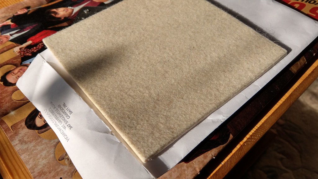 IMAG1625 IMAG1625, on Flickr With this, I could finally assemble the wheel, axle and axle box sets. I had originally intended to have the axle boxes in place when pressing on the wheels - but it seems that the act of pushing the axle through the box disturbs the felt, so it seems I'll need to split the boxes instead. This however does mean I can assemble each axle without the axle boxes in place. I took the opportunity whilst it was all apart to remove the machine marks on the various faces. Here you can clearly see the oil reservoir in the top, and the recess for the felt pad in the keep.  IMAG1626 IMAG1626, on Flickr And here is everything split down to its component parts. I know I've shown these boxes multiple times, but I am rather pleased with them - I'd say they're the most complex item of machining I've done to date.  IMAG1627 IMAG1627, on Flickr With one box polished and my short attention span, I decided to 'press' the trailing axle and wheels together. I don't actually have a press, so this set up would have to do.  IMAG1628 IMAG1628, on Flickr 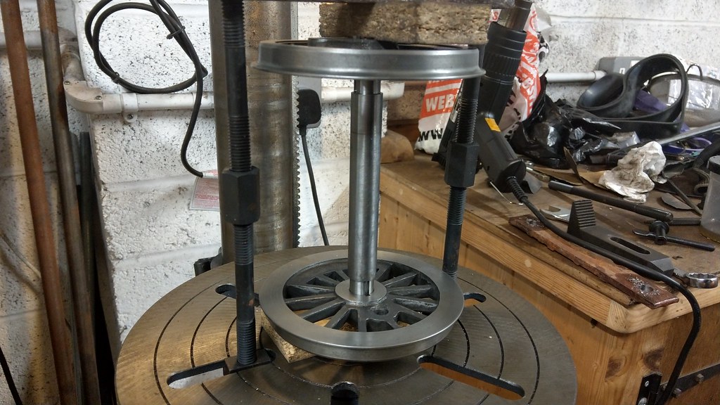 IMAG1629 IMAG1629, on Flickr It actually took much more force than I expected. 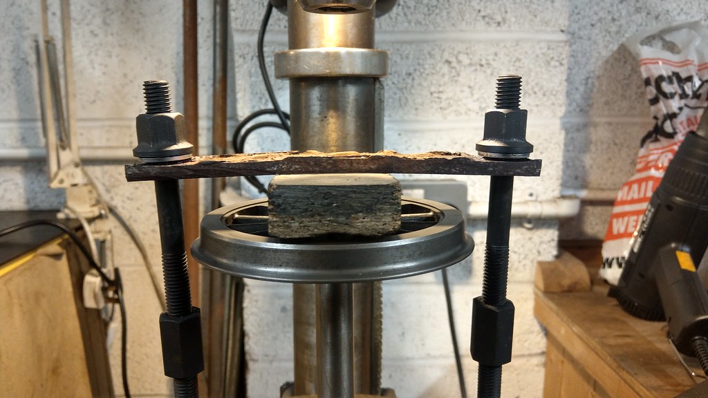 IMAG1631 IMAG1631, on Flickr I know I've shown an 'assembled' axle multiple times in the past too, but this time this is truly assembled with the correct axles and keys. I hope not to need to separate these again. And, of course, I had to try rolling it back and forth on my display track which is currently residing in the living room. 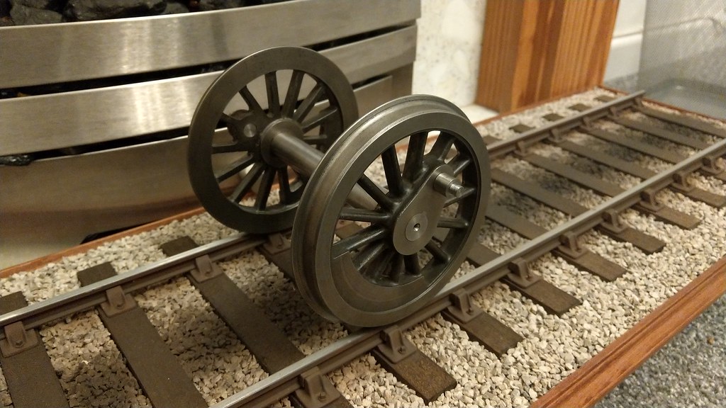 IMAG1634 IMAG1634, on Flickr 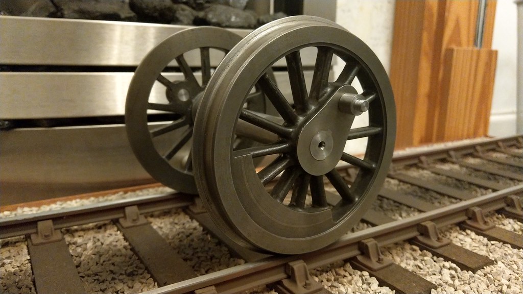 IMAG1636 IMAG1636 by Defiance Industries, on Flickr Hopefully, I'll have the other wheels assembled, all of the boxes cleaned up and a proper rolling chassis tomorrow. |
|
|
|
Post by Rob on Nov 4, 2018 22:07:09 GMT
This weekend has been mostly spent moving 36 axle box faces and associated retaining plates back and forth over wet and dry, so not too many pictures. I'm also happy to report I didn't forget to put the eccentric sheaves on the driving and leading axles before pressing the wheels on. After each box received the treatment I re-assembled them over the relevant axles, and finally reassembled the axle sets in the frames. 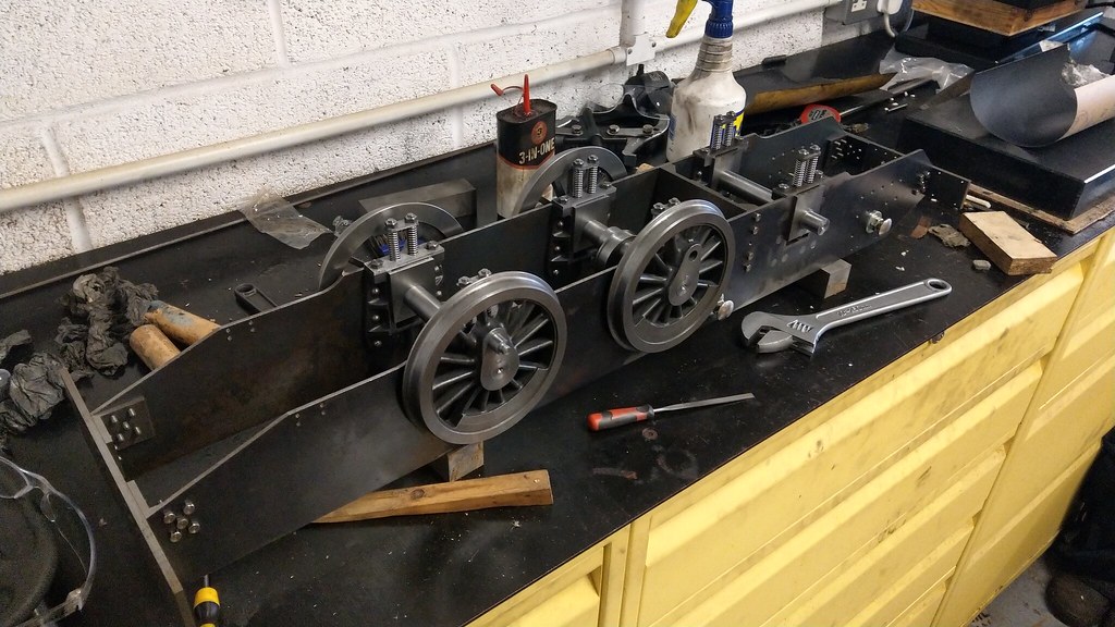 IMAG1645 IMAG1645, on Flickr I'm not a fan of set screws marking shafts, so I turned up some brass inserts for the sheaves. Had to make sure these didn't drop in the swarf tray otherwise I doubt I'd see them again. 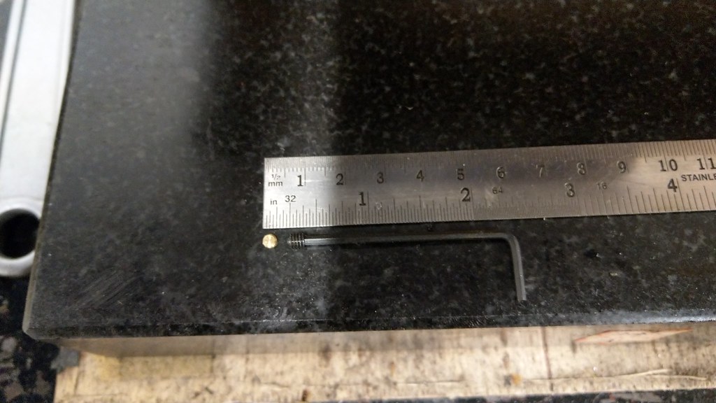 IMAG1647 IMAG1647, on Flickr And finally, after so many mock-ups, a completed rolling chassis. I hope I don't need to remove the wheels again. The frames now weigh 27 kilos, the idea of a rotisserie is starting to appeal. One thing highlighted this evening - the frames could really do with more bracing in the rear. There is one stretcher to go in for the brake cylinder, but I think it could really do with another. I wonder what's there in the full size... 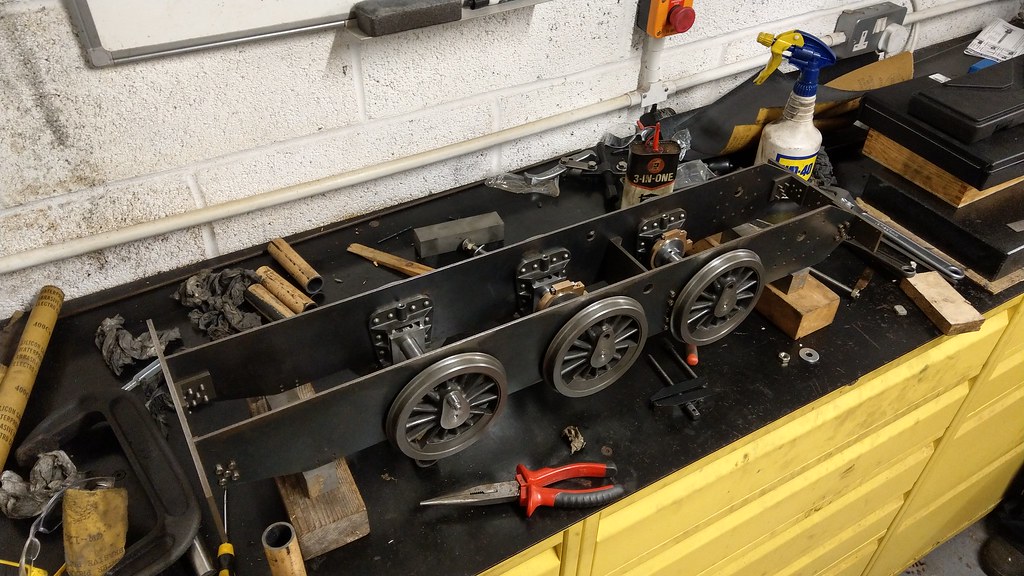 IMAG1649 IMAG1649, on Flickr Next up are the driving and leading crank pins, and then I think I'll make a test coupling rod to see how clever (or not) I've been so far. |
|


