|
|
Post by Roger on Nov 27, 2014 15:41:23 GMT
Well, you're hopefully going to machine the frames back to back so that the horns will be the same on both frames. Personally, I'd then fit the axleboxes to the horns and get the fit exacly how you want it. This can be quite a long process and if the holes are already in the axleboxes, that's just something else to worry about. I think you're better off doing the axle holes last when you know that the axleboxes are all correct and the reference face of the hornblock is correctly related to the face on the axlebox.
Once all that's right, a fixture makes sure that the hornblock face will be the same distance from all of the axlebox centre lines. I don't think there's a more accurate way of doing it but I stand to be corrected.
I don't see why you can't get the axles to within a few tenths of parallel to each other without much difficulty if you go about it that way.
|
|
|
|
Post by Deleted on Nov 27, 2014 18:42:41 GMT
Hi Rob I've just been reading your concerns regarding getting the axleboxes accurate....I don't have Don's words to hand just now but I'm sure that for my tender I put each pair back to back in the 4 jaw, this should ensure that at least the axlebox centre's are correct for each axle. Also as i have seen mentioned before if all else fails you can always fall back on shims....this may sound a bit heath robinson and to be avoided as a last result which I'm sure we will all do but i would say that this is basically similar to full size practice although there they use adjustable wedges to keep things square. I'm in the middle of reading Don's auto biography that Julian kindly lent me.....You'd be amazed at how close what we do in miniature was also the method for full size although admittedly on a much grander scale....very enlightening is Don's book and has reduced a lot of my own concerns on how accurate things need to be.....just do your best...I'm sure that she will run fine......have fun....  Pete |
|
|
|
Post by Roger on Nov 27, 2014 20:07:52 GMT
I think it's worth going the extra mile for the coupling axles, any errors will have to be accommodated at a later date when the rods go on. Tender or bogie axles are a different story where you can get away with a lot more error.
You can spend a couple of extra hours at this stage, or spend more than that later trying to deal with the consequences of not bothering. Either way you end up with a nice rolling chassis but the former is likely to be a lot less stressful. I'm afraid you can't hide from the brutal truth that the geometry faces you with when those rods bind up or you can't get them on at all.
|
|
|
|
Post by Deleted on Nov 27, 2014 20:57:00 GMT
I think it's worth going the extra mile for the coupling axles, any errors will have to be accommodated at a later date when the rods go on. Tender or bogie axles are a different story where you can get away with a lot more error. You can spend a couple of extra hours at this stage, or spend more than that later trying to deal with the consequences of not bothering. Either way you end up with a nice rolling chassis but the former is likely to be a lot less stressful. I'm afraid you can't hide from the brutal truth that the geometry faces you with when those rods bind up or you can't get them on at all. I fully agree with you Roger...what i was trying to say to Rob is don't worry if things don't go to plan, there's a way around everything.....Don's book has been a real eye opener to me... love reading about the major overhaul he was involved with on Mallard and how things were done full size in valve timing and about the trials after....great stuff... just wish I could read faster..alas my head seems to refuse to read more than a couple of pages at a time.....  Pete |
|
|
|
Post by Rob on Nov 27, 2014 21:04:46 GMT
Roger, perhaps you're right. I seem to convince myself one way and then convince myself another way is better. All of which leads to nothing actually being done, of course! I have already machined the frames back to back so the jaws are the same both sides, no worries there. Pete, of course you're right too. I've said to someone in the past that whilst I'd love to build the most efficient loco I can, I'll be damn pleased if it works at all |
|
|
|
Post by Roger on Nov 27, 2014 21:29:45 GMT
That's what I do when the going gets tough too, but it doesn't hurt to agonise over these things and weigh up the pros and cons. All I know is that if you want to make a setup repeatable, you have to have precision faces, clocked up and firmly held. The item you're locating against them needs to locate against the actual surface you're referencing too not an alias. In other words, don't reference to the flanges when what you're interested in is the face that actually mates with the horn. It's dangerous to assume that the flanges are all the same, even if they've been machined similarly. There's no point it taking the risk.
One of those statements I made excludes the use of a moving jaw of a 4-jaw chuck as a reference. It isn't rigid and it won't repeat anywhere near as well as a fixed surface. Try it if you don't believe me. Take a piece of round bar and clock it up as good as you can get it. Then release two jaws and tighten them up again. You'll be shocked at how badly it repeats. Why take the risk of that being the error between axle centres?
There's nothing to stop you bolting pieces to the faceplate that locate on the axleboxes. Again, people think it's a crime to add holes to a face plate, I don't. It's usefulness is enhanced if you add holes where you need them. You've paid for it, so drill holes where you like. You can always buy another one if it ends up like a piece of Swiss Cheese.
|
|
|
|
Post by Rob on Nov 27, 2014 21:47:30 GMT
I had thought about bolting clamps in strategic locations on a faceplate to use as locating points, but assumed that wouldn't be a good idea - I also thought about using one half of a keats angle plate, because it's a V shape. Obviously, that won't work if you're using the slots as the reference face, but this was when I was thinking of adding the holes first.
|
|
|
|
Post by Roger on Nov 27, 2014 23:16:53 GMT
My old boss used to say 'Think like and Engineer', and that's exactly the process you're going through. To me there's no difference to a beautifully engineered fixture or something well thought out but temporary on a faceplate or Keats angle plate. The part you're locating only knows the faces it's sitting against, the rest can be anything and rough as old boots. The key thing is to decide on what the the three faces you need to reference and how you intend to hold the work against them. The hole in the middle of the faceplate is a problem for locating the back, so something needs to cover that and be flat. You can machine that flat once it's attached. You can make a couple of pieces of mild steel to bolt to that, one with an undercut so the flange on the axle box doesn't touch it. Then you need perhaps a toolmakers clamp or another piece with a couple of threads to push the axlebox against the chosen reference faces.
These are all the things that went through my mind when I devised my fixture. I also wanted to avoid a clamp on the face of the axlebox so I could use it on the surface grinder too to set the thickness. Ok, I went over the top, but that's just the way I am. You don't have to do anything as elaborate as that, it's the principle of the way you reference each face that matters, not what the fixture looks like.
|
|
dscott
Elder Statesman

Posts: 2,438
|
Post by dscott on Nov 28, 2014 9:54:29 GMT
In the days of the Myford and Boxford faceplates were the part of the lathe and preserving them intact have become ingrained
just like the not having a smile on the table of the drill press! or Swiss cheese in your drilling vice!!
There is nothing stopping us bolting a cover plate onto the faceplate with a mass of tapped holes. With the introduction of
lathes with bolt on chucks we can now make a very simple selection of plates each one ready for its intended use.
In industry this is called the pallet system and is also very useful on the milling machine as you can cut into them to go
full depth and of course build up on them to support and tap holes wherever you want for clamps etc.
|
|
|
|
Post by Rob on Nov 30, 2014 22:29:22 GMT
Just a quick one this evening, I usually prefer to save a couple of pictures up but as I was particularly pleased with how these turned out I thought I'd post them up: 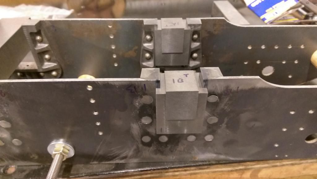 First two axleboxes in the horns, still oversize, but they fit well, no play but free movement, they slide back gently with gravity which I think is a good fit. I lapped them in a little with some plain engine oil, which actually worked surprisingly well. I know I'll need to relieve the slots to allow the axles to tilt, but I'll do that once I have them all together. Also highlights my dodgy riveting Cheers, Rob |
|
|
|
Post by Deleted on Nov 30, 2014 22:33:18 GMT
Nice work, matey------------ those rivets can be dressed down a wee bit...
|
|
jma1009
Elder Statesman
Posts: 5,901
|
Post by jma1009 on Nov 30, 2014 22:51:58 GMT
hi rob,
that is really excellent progress! very well done!
cheers,
julian
|
|
|
|
Post by Roger on Nov 30, 2014 23:11:45 GMT
Excellent work Rob, you're right to be pleased. I followed Julian's advice and added two pins to hold the inner parts That worked out really well. I bought some hardened dowels for those and reamed the holes so it's all nice and snug.
|
|
|
|
Post by Rob on Nov 30, 2014 23:25:45 GMT
Thanks chaps!
Alan, those rivets are near as damnit flush, the (enormous) gap around the one on the top right was due to me being a tad over-zealous with the countersinking, and not hammering the rivet square. You can see smaller gaps around some of the others, I'll need to fill those with something and file it back again. I learnt my lesson when doing the other rail!
Roger, I plan to do the same, I have some 3/16 silver steel for the job though I only bought enough for a single pin, so some more is on order. Hopefully it'll turn up soon, I have stuff outstanding still from before the Midlands show!
I need to do a little more fettling with my keeps, I hadn't noticed how much the end mill I was using had worn so the bottom corners of the slots need attention.
Cheers,
Rob
|
|
|
|
Post by Roger on Nov 30, 2014 23:36:01 GMT
I had the same problem. I'd use one long end mill for roughing and a new one for finishing if I was doing it again.
|
|
dscott
Elder Statesman
Posts: 2,438
|
Post by dscott on Dec 1, 2014 18:50:45 GMT
I have had great sucess with a smaller countersink using a centre drill, this also has the benifit of giving you
a much smaller face to file. Also a smear of slow setting araldite especially if you are going to get the frames
oily then clean and paint later. Oil seeps out and upsets paintwork... But on a Speedy we want this effect.
|
|
|
|
Post by Rob on Dec 13, 2014 20:37:00 GMT
Progress is slow, but at least it's progress! Have finished the slots in all the axleboxes and they're all running smoothly in the horns. Now attention turns to pinning the keeps in preparation for the nightmare inducing axle hole boring. 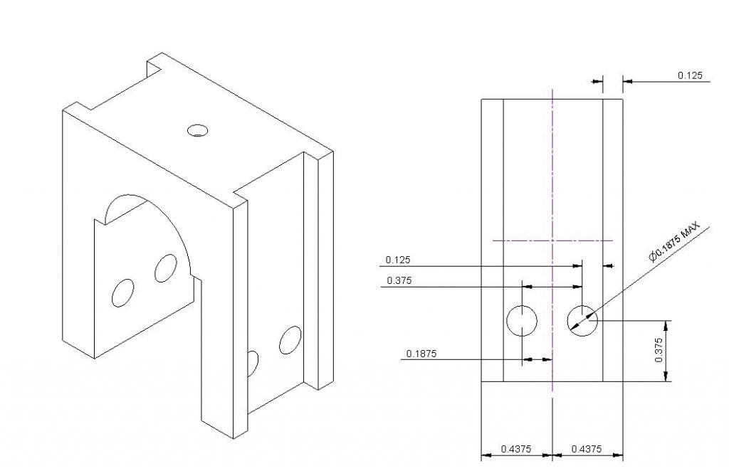 A modification to LBSCs axlebox design with twin pins for the keep as recommended by Julian and Roger. Still learning the 2D drawing side of Cubify, haven't yet worked out if there's an easy way to get the various dimension arrows lined up. I did these by eye, but there's got to be a better way! And the part in question: 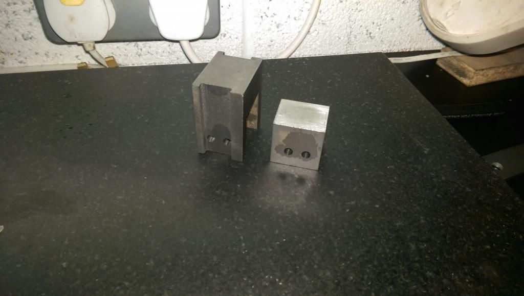 Still oversize, I think I'll finish it up to size in the lathe when boring the axle hole. 1 down, 5 to go! |
|
|
|
Post by Roger on Dec 13, 2014 21:29:51 GMT
Looking good Rob, it's a slow process but worth getting right. I was shown that it's better to put the dimensions off the ends of the part rather than coming out to the side. There are British Standards for all this but it's not set in stone. Sometimes you have to place them in less than ideal positions.
When you come to bore the axleboxes, just focus on getting the hole parallel to the horn block face. That probably means relying on one of the faces being perpendicular to those which it will be if the milling machine and vice were true. The position of the hole relative to the front horn face (say) on both sides is all that matters. It ought to be in the middle of the axlebox but that's of secondary importance. Don't forget to mark them up and remember that three will be one way round and three will be mirrored if you're clamping them to a fixed point that's locating in the slot. I wouldn't use the flange as a reference, that's may not be the same on each one. I'd suggest bolting a flat plate to the faceplate and attaching reference blocks to that so you've got some fixed reference points to guarantee that they all come out the same.
|
|
|
|
Post by Deleted on Dec 13, 2014 23:13:01 GMT
You can leave out the inner flange altogether as it offers nothing positive to the set-up... Also I'd put a slight curve on the outer flange..Together this will help eliminate any tendency for the boxes to bind on rough track................
|
|
|
|
Post by Rob on Dec 14, 2014 12:10:13 GMT
Morning Alan,
I will definitely relieve the outer flange but I'm leaving that process until I get all of the axles in place. I've noted that you've mentioned the inner flange before, so will bear it in mind!
Roger machined his flanges, but I notice you mention more of a curve - would you usually do that by hand?
|
|


