|
|
Post by Jim on Sept 5, 2015 21:49:14 GMT
Hi Steve,
I see that your trailing truck drawings along with my Perrier drawings show a straight rod and short straight slot for truck's centering spring and its coupling to the main frame. I'm not sure how this was supposed to work given the trailing truck swings on an arc and over club tracks, probably over a greater distance than allowed for by the short slot. Any thoughts?
As things stand, while I've fitted the two springs I've left it at that on Boadicea though I will fit a retaining clip of some sort to prevent the truck from dropping should the unthinkable happen.
Jim
|
|
|
|
Post by springcrocus on Sept 5, 2015 22:51:41 GMT
Hi Steve, I see that your trailing truck drawings along with my Perrier drawings show a straight rod and short straight slot for truck's centering spring and its coupling to the main frame. I'm not sure how this was supposed to work given the trailing truck swings on an arc and over club tracks, probably over a greater distance than allowed for by the short slot. Any thoughts? As things stand, while I've fitted the two springs I've left it at that on Boadicea though I will fit a retaining clip of some sort to prevent the truck from dropping should the unthinkable happen. Jim I'm not sure that I understand your concern, Jim. The maximum travel of the pony truck is controlled by the length of the pressure pads and their position, yet to be covered in my diary. The length of the upper slot is greater than this maximum travel and the hole through the spring return pin is, obviously, of a much greater diameter than the spring return rod to allow for this angular movement. The spring return pin also retains the rear of the truck, stopping it from dropping and losing the pressure pad cups if the chassis is lifted. My next post will be covering this aspect of the pony truck but it's possible that I have completely misunderstood what you are refering to. Just in case there is a major difference in our drawings, I will pm you tomorrow with a photo of the complete drawing so that you can compare it with your original Perrier drawing. Steve |
|
|
|
Post by Jim on Sept 6, 2015 1:22:36 GMT
Hi Steve, Your kind offer to pm me your drawings is much appreciated but mine are quite clear and basically identical to yours so all OK there. Likewise there is no misunderstanding, I was just interested in how you saw the straight rod and slot for the pony truck's retaining/centering mechanism working as the truck swings in an arc rounding curves and traversing points and in that regard you have answered my query. The pony truck is looking very nice indeed, you'll have a great model when all is complete.  Thanks again for your offer of the drawing but all is ok. Jim |
|
|
|
Post by springcrocus on Sept 12, 2015 14:17:36 GMT
I have made the pony truck pressure pads from a length of 1" x 3/16" flat brass bar which I hacksawed off at 1.3/8" long and then milled down to 7/8" wide. Next, I marked out the mounting holes and drilled them 6BA clearance and also made up a filing button to help me form the outside semicircles at each end. I had started to mill out the inside form but then realised it would be smarter to get the outside finished first.  The inside was just milled out freehand using a 1/4" dia cutter and nibbling away at the ends to get an approximate curve of 3/4" diameter. It's not that important since, once assembled, they cannot be seen, and the pad cups that ride in the channel should never reach the ends anyway.  They were then placed on the rear beam and spotted through, the rear beam was drilled and tapped 6BA and the pads were then bolted down with 6BA countersunk brass screws.  The pad cups are made from some 3/4" dia brass bar and were machined in a single operation in the lathe. After centre-drilling and drilling a 1/8" dia through hole, the main radius of the cup was formed using a ball-nosed slot drill held in a holder in the tailstock. This was done very slowly and with everything locked up as tight as I could get it yet still being able to wind the tailstock handle. Then the diameter was skimmed to clean up, the angle turned at the front and finally parted off. I also made the pads for the front bogie at the same time since they are the same size. The final part needing to be made was the spring return pin for mounting on the dragbox. This was just a piece of 10 swg steel sheet cut to make the base, with the bolt holes drilled 6BA clear and a 3/8" diameter steel pin riveted to it. I have made mine a bit different to the drawing, and made it position-adjustable.  Offering up the whole assembly to test the fit, this is where it all started to go pear-shaped and the fun and games began. The first problem to manifest itself was the overall length from the kingpin to the centreline of the rear beam. I checked all the dimensions and found that the casting dimensions differed from the drawing, something I should have checked at the beginning but didn't so my own fault. To rectify this meant making a new bronze bush to fit into the casting and marking out a new position for the kingpin hole. Luckily, there was enough wall thickness to accomodate this but it was a bit close.  The next problem I found was that the cups were fouling the sides of the pressure pads near the extremity of travel and riding up. The simple answer was to skim twenty thou off the diameter of the cups and after that, they slid side-to-side perfectly. Now was the time to measure the centre-line height of the spring return bar from the dragbox to enable marking out and drilling of the cross hole in the spring return pin. My spring return bar is 5/32" diameter so I drilled the cross-hole 7/32" to ensure there was plenty of clearance so that there would be no fouling at the extremities of travel. This is because of the radial motion of the truck. At this point I bolted the spring return pin loosely to the dragbox and put the pony truck onto the kingpin and the pads.   Then the spring return bar, minus the springs, was pushed right through and the spring return pin centred by eye before tightening down. Finally, the bar was withdrawn, and reloaded complete with the springs.  At this point, the rear of the truck is now captive and the clearance is such that the pressure pads and cups won't be separated if the locomotive is lifted. I've just got to sort out how I'm going to fix the lower cover to the rear beam, and make the axlebox springs and associated bits. Then, apart from a bit of cosmetic work, the pony truck will be complete. Thanks for looking in Steve |
|
stan
Seasoned Member

Posts: 110 
|
Post by stan on Sept 12, 2015 21:45:33 GMT
Hi Steve
Just a quick question how did you secure your Timken covers as the ones I have are Doug Hewson white metal, if you stuck them what did you use.
Stan
|
|
|
|
Post by springcrocus on Sept 12, 2015 21:49:08 GMT
Araldite Original ( the 24 hour stuff)
Steve
|
|
stan
Seasoned Member

Posts: 110 
|
Post by stan on Sept 13, 2015 21:03:34 GMT
Thanks Steve im pleased you didn't say soft solder
Stan
|
|
|
|
Post by springcrocus on Sept 19, 2015 15:24:44 GMT
The drawing shows the two firebox brackets on the pony frame to be made from 3/16" material but I didn't have any and nor do I fancy bending steel at this size. However, I do have some 5/32" thick rectangular box section so the brackets were made from a lump of this. It's perfectly strong enough and I don't know why 3/16" was chosen by the designer. First job was to hacksaw a slice off the end of the tube and clean it up to 1/2" thick. I did this in the lathe using my independant 4-jaw chuck.  The two brackets were then cut from the piece, linished up, marked out and drilled for 6BA clearance.  I haven't checked the boiler / firebox drawing but I assume that the milled reliefs on the brackets are to clear the dragbox and that the brackets mount inside the frames.  I also made the two ashpan hinge brackets out of some 3/8" square brass and bolted these on with 8BA bolts. Instead of 5/32" for the hinge pin, I shall use 4mm, simply because I have a 4mm reamer but not a 5/32" one.  Pretty simple stuff but just trying to clear up some of the last few bits that fit on the pony frame. Final picture seems to have gone walkabout. Thanks for looking in. Steve |
|
|
|
Post by Deleted on Sept 19, 2015 15:27:53 GMT
nice piece of lateral thinking there Steve...love it...  Pete |
|
|
|
Post by springcrocus on Sept 26, 2015 12:33:42 GMT
I am making all of the coupling rods from general purpose black mild steel, probably EN3 grade, because I think there is less chance of the rods distorting after machining. The material I am using came from a forge that manufactures gates and railings. I started with the front coupling rods and the first thing I had to do was get them finished to length and one edge cleaned up so that I could mark the outline of the front rods onto the surface. 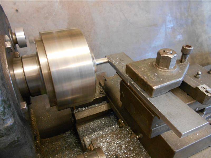 After this, I marked out the centre-line of the bearing bores and the distance in of the first bearing, and drilled a 1/8" hole. Then, using my beam compass, I accurately set the distance between the leading and centre axles and then transferred the second hole to the front rods.  Next, I finished marking the rods out and drilled the third bearing position and I shall spot through this hole when I make the rear coupling rods. 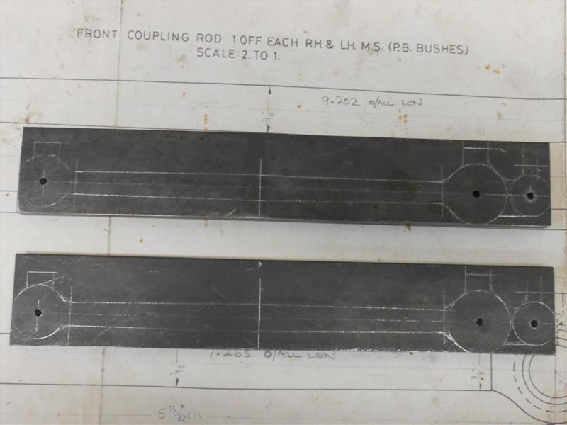 Back to the lathe and plenty of roughing out with a 12mm centre-cutting end mill (because I have loads of them) and then over to the vice and an hour with a carbide burr and sanding drum in my dremel.  I have used 8mm thick material so they need thinning down to 1/4" and the coupling rod reduced again to 3/16". This was done with four setups each side due to the travel of my mill table.  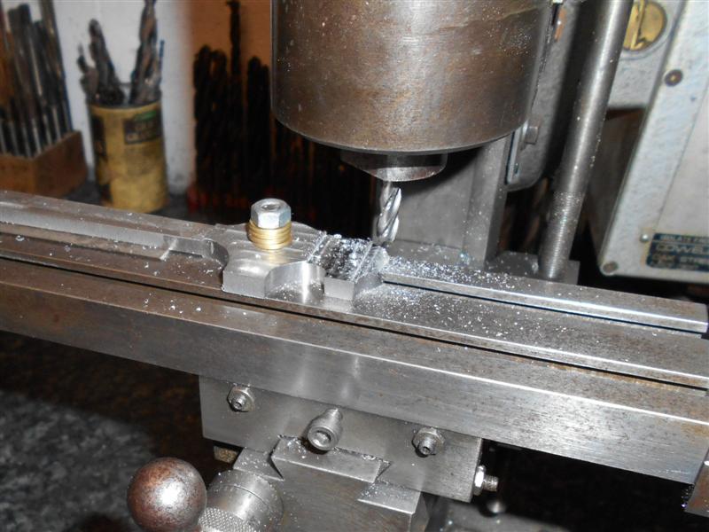 To get the transition from the the 1/4" thickness to the 3/16" I bolted the rod to a small faceplate and used a 10mm end mill to form the radius. This is the maximum size endmill that I can hold in the Cowells mill. I smoothed the transition further using a sanding drum in my dremel.  The holes for the phosphor bronze bearings were opened up to size using a stepped drill. I don't have a 5/8" reamer but it doesn't matter as I shall make the bearing to suit. As long as you have control over one or other dimension that is all that is needed to get a good fit.  The bushes were just a straightforward bit of turning on the lathe although phosphor bronze is one of my most hated materials to work with. Drilling the hole is a pain because the stuff heats up and expands very quickly during cutting, then cools and contracts causing the drill to bind. A good tip is to grind the anvil of the drill slightly off-centre which causes the drill to cut on one side and, consequently, slightly oversize. This stops the binding, but you need to be able to regrind the drill to its correct form for normal use.  Finally, the rods were given a good polish all round before pressing the bushes in. 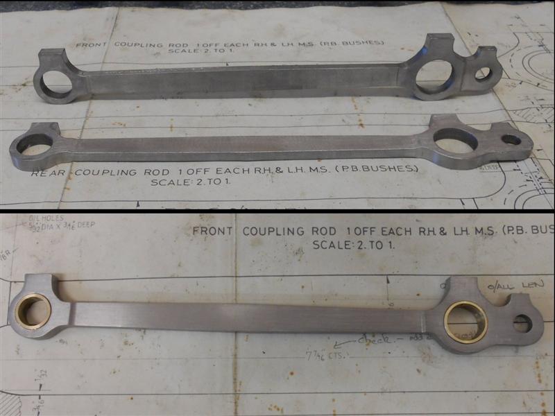 Now I just have to test them for fit and, if all is satisfactory, drill the oil holes in the top of the rods. Thanks for looking in. Steve |
|
|
|
Post by springcrocus on Oct 2, 2015 18:12:02 GMT
As written about previously, I had made my front coupling rods by marking out the hole centres with my home-made beam compass (described HERE) and using a step-drill to bring the holes to size prior to fitting the phoshor bronze bushes. Well, that didn't work, a big disappointment. When I offered the first side up, the wheels wouldn't pass the E-W positions which are the two points where the distance between the crank pins has to be identical to the distance between the axles. Get this right and the rest just falls into place. The beam compass was still set to the correct axle centres but when I offered it up to the rods with pins and buttons to suit, it was obvious that my method for drilling the holes was nowhere near accurate enough. I started by dressing the insides of the larger bearing bore with a small sanding drum but it soon became obvious that this wasn't going to work as I had at least a ten thou error. I decided to bite the bullet and remake the larger bushes using a deliberate offset in the bore so that I could adjust the bearing position for a good fit. First, I made up a couple of top-hat blanks, without the hole, to the correct sizes in the 3-jaw chuck.  Next I put the 4-jaw independant chuck on the lathe and loaded the blanks one at a time, clocking the O/D to get a total indicated runout (TIR) of about twenty five thou. Next I drilled through with a 1/2" drill, stopped the lathe and let the pressure off the chuck as I didn't want them deforming - the wall thickness is less than fifty thou at one position. Then I just nipped them up again and bored to the 5/8" finished size with a nice, sharp HSS boring bar. I don't have any particularly accurate instruments for measuring small bores and nor do I have a reamer so used a stepped plug gauge. Before trying to fit the first rod to the wheels, I aligned the crank pins on the wheels nearest to me at bang-on the 9 o'clock position and locked them together with a piece of flat bar clamped to the wheels on the other side. This made sure they stayed perfectly in position.  Next, I pressed the new bearings fully home - I had made them a light press fit - and by holding the shoulder of the bearing in the bench vice, I was able to rotate the bearing round to different positions until the rod slipped easily onto the crank pins.   Leaving this front rod in place, I turned the loco round ( no mean feat as it's getting pretty heavy now) and repeated the whole procedure for the other side. Once I had the other front rod a sliding fit on the crank pins, I removed the clamp bar and tested the rotation of the wheels. I am pleased to say that the wheels rotate freely with no hint of binding as the crank pins pass the E-W positions so that proves that my crank pins are in the correct position relative to each other (drilled with a drill jig) and that my wheel quartering is also accurate (using keys). The original error was inaccuracy in opening up the bearing holes to size. This is where having a larger mill with DRO would be a godsend but I don't have that luxury so have to adapt accordingly. To finish, I just need to drill the oil holes in the top of the rods. Luckily, I have been able to turn a disaster into a triumph without scrapping lots of earlier work, in this case having to completely remake the front rods. However, there is always a way round a problem and this one didn't require much extra effort to solve. Thanks for looking in Steve |
|
|
|
Post by donashton on Oct 2, 2015 22:10:08 GMT
Hi Steve,
I've just been going through your descriptive operation of turning disaster into solution. It is so common and annoying but it's bark is greater than it's bite. How pleasant to read that your diagnosis proved correct (quartering etc). Maybe being calm and collected didn't quite come until you came to write the script!
Thanks for sharing. It reminded me of a friend who foolishly jumped at a chance to overhaul a 3.5" 2-10-0. Stripped to a chassis and upside down on the bench one's attention was drawn to 5 axles all presenting different angles to the frames. Need I say more?
Oh, and the 'tendency to derail on some tracks' was verified as the wheelsets were just right for 3.563" Gauge track!
Sorry Steve - got carried away there.....
Don.
|
|
|
|
Post by Roger on Oct 3, 2015 7:54:17 GMT
That's a neat and clever solution Steve, and it made me wonder if that method would be a good one for making a drill jig when making rods. The bearing with the eccentric hole could be hardened to guide the reamer, and inserts could guide the drills.
|
|
|
|
Post by springcrocus on Oct 10, 2015 18:51:56 GMT
I haven't been able to get anything done in the workshop this week but I've had the slide bar brackets written up for a while so thought I'd post these up today. I have made the slide bar brackets using the gunmetal castings that are available since they are a better casting than some of the other offerings for this loco. However, I made these parts sixteen years ago and don't have any pictures of how I made them. I was also able to use the Bridgeport with its DRO so was able to make them much more easily than if I had to make them today. I do have my notes to refer to and will describe how I made them as best I can. The four photos were taken recently, however. First job was to machine the outer edges to get them square and to finish sizes. Then they were dropped into a large milling vice and the back face cleaned up followed by some work on the underside, just to pretty them up. Then I drilled and tapped the 8BA holes for the lubricator mounting plates and also the holes for mounting the slide bar brackets to the mainframes. Usually, these would be spotted through from the frames but co-ordinate drilling with a DRO is far more reliable than marking out by hand.  The job that needed reasonable care was the machining of the angle where the top slide bar bolts to. Although the angle is not shown, dimensions are given to indicate the change of height over the width of the bracket. For me, this is a job that can most easily be done with a sine bar and I calculated the slips needed to lift the bar to the correct angle. In my case, the sine bar centres was 6" and the width of the slide bar bracket is 2.1/4" so multiplying the amount of rise (0.182" - 0.080" = 0.102") by 6 and dividing by 2.25 gave me 0.272" and slips to this value were wrung together and set under one end with the whole lot set up against an angle plate. The slide bar bracket was then clamped to the angle plate and the surface machined. Using the same setup, I also drilled the slide bar mounting holes using co-ordinate positioning with the DRO. Finally with this setup, I upended the casting and cleaned up between the webs and the end sections so that the bolt heads had a machined surface to locate against. 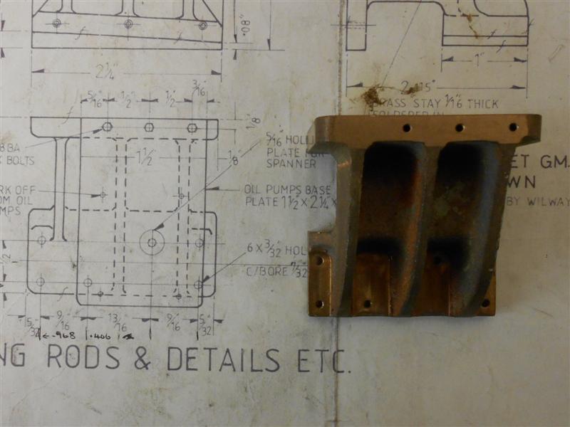 To complete these parts, the rib nearest the cylinders was cut back to provide clearance for the rear valve guide and the castings given a bit of cosmetic work with the dremmel. The lubricator mounting plate is just a couple of bits of 16swg brass cut to shape, drilled, and soldered together prior to bolting to the top of the slide bar bracket. 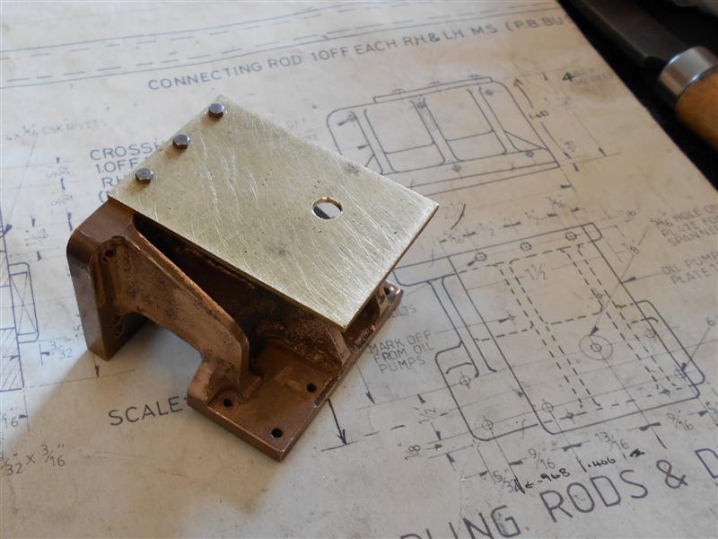  I have deliberately drilled the holes in the frames four thou larger than usual to allow a bit of adjustment when the time comes to set everything up. I have also reduced the width of the slide bar brackets by 1/16" to facilitate the mounting of the footplate brackets that fix to the frames right next door. The drawing dimensions are incorrect and the footplate brackets cannot possibly fit as drawn. Thanks for looking in Steve |
|
|
|
Post by springcrocus on Oct 17, 2015 20:19:58 GMT
The kitchen has taken precedence again this week, plus a day out to the Midlands MEX so this is from the archives, as it were. Although the drawing specifies mild steel, I have made the slide bars from ground flat stock using 3/4" x 3/16"" for the upper bar and 1/4" x 1/4" for the lower two bars. The reason for choosing this material was because it has exceptionally good straightness and I want the crosshead to travel along the guides without any high spots causing binding. I also milled down a couple of offcuts of the 1/4" square to make the packing pieces for either end, making sure I had them both of equal thickness for the same reason.  There is nothing special or difficult about making these parts, just some simple milling and a few drilled and tapped holes. The relief sections of the bars were milled out first followed by the angled sections at each end of the bars. Finally the holes were marked out, taking special care to get them accurate because I want a good fit to the flimsy 8BA bolts that will hold the assembly together, and then drilled and tapped accordingly.  They need a bit of a polish and the edges stoning to finish. I covered the making of my crossheads in a separate thread HERE so wont go into detail about these now but here is a picture of the whole assembly mounted to the frames.  Once assembled, one side was a bit sloppy with some vertical play so I reduced the spacer pieces on that side by a couple of thou and achieved a much better fit. Thanks for looking in Steve |
|
|
|
Post by springcrocus on Nov 8, 2015 18:21:50 GMT
After faffing around with my kitchen refurbishment for the last four weeks, it's really pleasing to have been able to get some workshop time this weekend. So we have some progress... I have made the rear coupling rods in a similar fashion to the front coupling rods as described earlier and using the same 8mm black steel that I bought from the forge. It has actually been a nice material to work with and quite unlike some of the GCQ (Good Commercial Quality, although we used to call it Generally C**p Quality) that I've machined in the past. After marking out and drilling I machined the main part of the rods on the lathe (see previous post for pictures) followed by forming the shapes of the bosses with carbide burrs and sanding drums in the Dremmel.  Then the arms were thinned to 3/16" on the milling machine.....  ....followed by drilling the holes and dressing at the workbench.  I also had to put the 5/32" slot in at the driving end and opted to cut this using a slitting saw mounted in the lathe chuck.  Being a little wiser this time, I knew the holes wouldn't be that accurate and have made the bushes in the independant 4-jaw chuck from the off. I started by setting up the wheels with all the crank pins at the nine o'clock position on one side and clamped the wheels in position, making sure that the front rod slid easily into place.  Then I removed the rod, coupled it up to the rear rod and offered it back up to the crank pins. This time I was able to use miniature drills as feelers to find how much offset I needed and once I knew this figure, I added a couple of thou to give me the amount of runout (TIR) I needed to set on the O/D of the bush. The phosphor bronze bush was then made the same way as last time, pressed into the rear rod and adjusted until all was a nice fit.  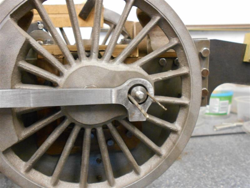 Then the loco was turned and the operation repeated on the other side. This last picture shows the lefthand side where the speedo will go once I've made the bracket.  And this time, all the wheels turned nicely with only the faintest hint of binding. A little bit of judicious polishing and some running-in time will probably sort this so I won't do anything further at this stage. I also need to make a pair of case-hardened pins to replace the temporary ones I used to join the two rods. Although the bushes have this offset, once the motion is fully assembled they cannot be seen so I am quite happy to leave this arrangement as it is. And in case anyone is wondering, the axleboxes are resting on packing pieces set in the top of the horns to simulate the expected ride height when the loco is finished. Thanks for looking in. Steve |
|
|
|
Post by springcrocus on Nov 14, 2015 16:34:01 GMT
I was going to make the connecting rods next but it looks like I will getting my new mill before Christmas so have decided to wait till then before making them. Although I enjoy the challenge of making biggish things on my little Cowells mill, I'm not a glutton for punishment! It's not set in stone yet, but I'm leaning very strongly towards this one because I particularly want to be using R8 tooling. It's identical to the Amadeal one although with a slightly larger motor (and cheaper) and almost identical to the Warco WM16. Unfortunately, Warco do not do R8. Buying this leaves enough funds to buy a 2-axis DRO, clamping set and a few tools. Instead, I have been getting on with the front bogie and will update the diary tomorrow night, if all goes well. Steve |
|
|
|
Post by Roger on Nov 14, 2015 17:08:01 GMT
Hi Steve,
Can that one have a packing piece to lift the head up? There's not much room left once you've put a vice on that table.
|
|
|
|
Post by Deleted on Nov 14, 2015 17:43:18 GMT
Hi Steve, Can that one have a packing piece to lift the head up? There's not much room left once you've put a vice on that table. If it's the same as my WM16 and it certainly looks like it, there is plenty of working height. The whole head moves up and down the dovetailed column by turning the hand wheel at the top, I can't remember how much it moves by but I can say the I've held some very large items for machining...there's plenty of scope for anything ME related...the spindle itself has 50mm movement on top of the head movement. Pete |
|
|
|
Post by springcrocus on Nov 14, 2015 17:51:29 GMT
Hi Steve, Can that one have a packing piece to lift the head up? There's not much room left once you've put a vice on that table. There's 370mm distance from spindle to table so plenty for me. I made up a comparison spreadsheet  You can download a copy from here if anyone's interested. Steve |
|