|
|
Post by Roger on Nov 14, 2015 18:25:13 GMT
Oh, that's good then. It's deceptive in the picture, it doesn't look like there's much. I think R8 is a good standard with plenty of choice of attachments.
|
|
|
|
Post by springcrocus on Nov 14, 2015 19:27:04 GMT
Part of my reason for wanting R8 is that the collets are practically flush with the spindle nose and end mills / slot drills can be held right up to the flute, so very rigid indeed.
Steve
|
|
|
|
Post by Roger on Nov 14, 2015 19:37:47 GMT
Excellent, and you can get an Easychange adaptor for it too if you really want to push the boat out later. |
|
|
|
Post by vulcanbomber on Nov 14, 2015 19:52:43 GMT
The R8 system is very good for tool holding. Its down side is its length but I find that a small price to pay.
|
|
|
|
Post by springcrocus on Nov 14, 2015 22:30:42 GMT
If it's the same as my WM16 and it certainly looks like it, there is plenty of working height. The whole head moves up and down the dovetailed column by turning the hand wheel at the top, I can't remember how much it moves by but I can say the I've held some very large items for machining...there's plenty of scope for anything ME related...the spindle itself has 50mm movement on top of the head movement. Pete Pete - serious question. How often have you wished you'd bought the WM18 instead of the 16? Have you found the smaller table of the WM16 to be a frustration? I am toying with buying the larger machine BUT that would leave very little in the pot for extras, particularly the DRO. Much as I would like the larger size, I think the DRO is more important than the extra 140mm on the table length. Would greatly appreciate your opinion. Steve |
|
|
|
Post by Deleted on Nov 14, 2015 22:54:01 GMT
Hi Steve
That is an easy question to answer....I have not come across anything yet that made me wish that I had bought a bigger machine...yes I guess the bigger the better but I haven't found the WM16 wanting yet...except for one thing.....I don't have a DRO and that is a hindrance....now some will say..'use the dials'....that's fine if you trust them...I don't....not the graduations themselves which I have found accurate, or as accurate as they can be reading from a graduated disc. However some times the dial has moved without the graduated disc itself (disc sticking) thus loosing the reading, I should probably look into this but have not done so to date, probably needs a good strip down/service. In place I use digital scales but if I could afford it a DRO it would be a most welcome sight, far more important than having a larger machine. The table on the WM16 is pretty big for this sized machine, certainly big enough for my build.
So to summarise....yes of course I would love a bigger machine, not that it would fit in the workshop though...would I prefer a DRO more?...you bet.
Pete
|
|
|
|
Post by Roger on Nov 14, 2015 23:09:30 GMT
That would be my choice too, a DRO is a game changer whereas a bigger machine is not. A bigger machine is always going to be desirable, I'd dearly love a Bridgeport converted to CNC, but in reality it wouldn't make much difference. I couldn't reach to profile all the way round the frames even on my little locomotive yet I've got a decent sized machine. There will always be jobs that you can't do in one operation but it doesn't happen enough to justify the expense.
|
|
|
|
Post by Rob on Nov 14, 2015 23:44:47 GMT
I have the WM18. I'm able to fit the entire chassis of my 15xx on the table, though I don't have enough travel to reach the extremities. I was able to reach all of my hornblock jaws in one set up.
My only criticism of the WM18 (and all the other designs like it) is the Z axis. When tightening and loosening the locks the head moves by a significant amount. This means that once you've trammed it in with the axis locked, you can't use the Z axis unlocked for milling. It's only use is to move the head up and down between operations. That's fine, I can live with that, but it would have been nice to have the added flexibility of a decent Z axis. It may be just my machine, but I think it's likely a problem with them all. I've tightened the gib to the point that the axis is now stiff to use, and the head still moves.
If I was buying again, I would look for something a little bigger with a knee I think. I have no reason to change mine at the moment though, it's done everything I've needed of it.
I fitted a DRO to my mill shortly after purchasing it. I think I paid about 300 quid for it, far cheaper than paying Warco to fit one from the factory.
|
|
|
|
Post by springcrocus on Nov 15, 2015 7:28:42 GMT
I've just edited an earlier post to include a screenshot of the spreadsheet I had made as some people wont be able to see it. When comparing the specs of various machines it becomes obvious that they are all from the same stable with different badges on them. Steve |
|
|
|
Post by springcrocus on Nov 17, 2015 15:33:51 GMT
Halloooooo, is anybody left out there? I do hope I finish Britannia before everybody leaves to take up astronomy or play call of duty.  I made the front bogie assembly many years ago but there are still some bits needed to finish it. The two side frames were marked out and then cut to shape, using hand tools only, before co-ordinate drilling all the holes using the Bridgport with its DRO. There were also quite a few components that had to be made and rivetted to each side prior to rivetting the two end stretchers including the horns, the guard irons, the lower spring supports and the pressure brackets.  The inner horn blocks needed to be cut away to clear the equaliser bars but I didn't remove enough metal before assembly, hence the saw marks on the sides. One of those situations where I wish I had used rivet-headed screws instead or rivets, they could have been dismantled and worked on further. The main centre bogie stretchers, which are also the guides for the sliding block, were also made at this time but I had chosen to fix these using screws instead of rivets. 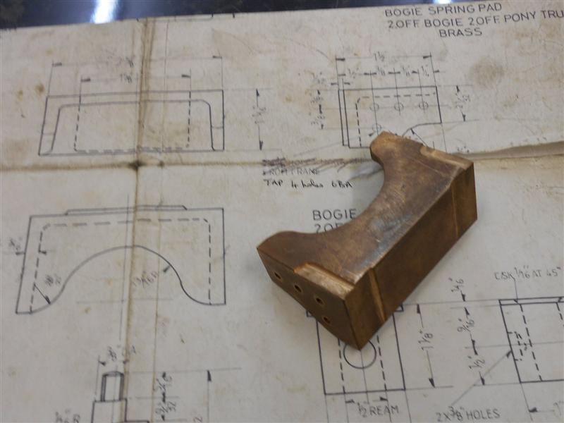 Below are a couple more pictures of the bogie assembly.   Thanks for looking in Steve
|
|
|
|
Post by Deleted on Nov 17, 2015 16:55:27 GMT
Don't tell everyone but I have played COD and I'm very much into astronomy.....  Nice work as per usual Steve.... Pete |
|
|
|
Post by miketaylor on Nov 17, 2015 19:21:35 GMT
Hi Steve, There are a lot of people out here, regardless of whether they like astronomy or CoD. (I was one of the ones who said "CoD?  "). Take heart from the forum stats. You have 19000 views on 230 posts. That's a lot of people who, like me, read your every post and eagerly await the next one. Keep em coming. Mike |
|
|
|
Post by springcrocus on Nov 17, 2015 19:34:41 GMT
I'm fine, don't mind me.  But thanks for the concern anyway. I was making a somewhat cynical reference to the debate going on both here and over on the ME site.  Lots of armchair engineers around lately... Those who visit the other forum will know what I mean. Steve |
|
|
|
Post by springcrocus on Nov 21, 2015 22:29:24 GMT
Before the bogie could be coupled to the mainframe, I first had to make a few related parts. The first of these was the bogie kingpin which fixes to the middle of the bogie stretcher. This was made from some 7/8" diameter mild steel just held in the 3-jaw chuck and the pivot end turned down to 1/2" dia by 1.3/4" long followed by reducing the front to 1/4" dia and threading 1/4" BSF. I didn't form the two tapers at this point as I wanted to chuck on this diameter to turn and thread the opposite end.  After the second end was done, I reversed the work once more, holding on the short length of 3/8" dia and machined a slight taper from the front to the half-way mark using ther compound slide set at about two degrees. Then I set it over the other way and ran from the middle to the shoulder, finishing off with some emery cloth to blend it all in. I wasn't bothered about concentricity for this, nor are the sizes overly critical - a couple of thou under nominal seemed about right. Next I had to make the sliding block which fits between the centre stretchers and drops over the kingpin. There is a gunmetal casting available for this but I had a lump of bronze available so used this instead. This was made many years ago but my notes remind me that I first faced up the billet in the lathe and drilled the hole 7/16" diameter. Then I turned the billet round, faced the opposite end to length (1.1/8") and then bored and reamed the 1/2" hole to size.  I then loaded the block to a 1/2" diameter mandrel held in a 4th axis chuck on the table of the bridgeport and machined all the sides, finishing off by putting the spring retaining reccesses in with a 3/8" dia slot drill. The photo does show one difference from the drawing, the four tapped holes in the bottom of the block that I will explain once the bogie is fully assembled. The final thing I needed to finish before assembly was the bogie pressure pads which transfer the weight of the loco onto the bogie pressure brackets. These were just some simple milling of the gunmetal castings followed by pressing in the spherical pads which I made at the same time as the pony truck pad cups but forgot to describe. They were made in a single operation using a form tool to create the radius at the front of the 5/8" dia brass bar...  ... followed by plunging down the back to create the 1/4" dia locating pin and finally parting off.  These are then bolted to the mainframe on the centre-line of the bogie stretcher.  The bogie can now be attached to the loco but would work better if it had some wheels! Thanks for looking in Steve |
|
|
|
Post by springcrocus on Nov 28, 2015 18:33:08 GMT
I have made the axleboxes in the same matter as I described here so wont cover the same ground again and, likewise, the axlebox covers. As before, I have dispensed with the oiling holes as I am using sealed-for-life bearings. If they fail in service, it's no big deal to press the wheels off and replace the bearings. The axles were turned from some 5/8" dia EN8DM. I roughed them out first just holding in the 3-jaw chuck and leaving about fifteen thou on the diameters but getting the 3.543" length bang on size. The bearing journal length of 0.572" is not actually that important as long as it is not over length. This is because the wheels are pressed on with spacer collars between the bearing and the wheel to set the back-to-back distance between wheels.  Second op was to hold on the bearing journal using some brass shim to protect the surface and turning the opposite end diameters using a rotating centre to keep things running true. The bearing diameter was machined as a light press fit and the wheel journal with a half- to one thou interference fit which will be tweaked later if needed, depends on how the reamer cuts. Once machined, I assembled both axles into their respective axleboxes and started polishing the horn blocks for a nice sliding fit of each assembly. I will probably need to ease these down to a light rattle fit later on but they will do for now.  Apart from pressing on the wheels, all I need to do now is fit the axle keeps below the horn blocks, then I can get on with the suspension. Thanks for looking in Steve |
|
|
|
Post by springcrocus on Dec 11, 2015 22:08:51 GMT
Because I have been waiting for my new toy to arrive, I've spent too much time waffling about things other than the build. Some jobs have been held over to await the arrival of the new milling machine so I decided to get these parts made although they are not really in sequence with the rest of the project. The drawing suggests using 2mm copper or brass sheet to fabricate the smokebox saddle but I had considered making it from mild steel. However, I couldn't find a local supplier so bought a lump of 14swg brass sheet at the Midlands MEX and used that. First, I cut out the blanks I needed, remembering to cut the width of the main saddle piece to the development length to accomodate the bending of the material. The four sides of the saddle support will be riveted together before soldering the saddle in place. 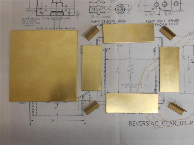 The crossways pieces are cut to fit exactly in the frames and the lengthways pieces are cut to the nominal dimension minus two thicknesses (0.160") and will fit between the two crossways pieces. Next I marked out the cutaways and then stitch-drilled them, removed the waste and cleaned up the shape will rotary burrs and sanding disks.  I also drilled and countersunk two rivet holes at each end for fixing the corner angle pieces to and am using 3/64" countersunk brass rivets for this. Once drilled, I clamped an angle piece flush with the end and drilled through the existing hole, countersunk the opposite side and fixed the rivet, repeating for each hole until both sides were complete.  Finally, I clamped the end pieces to the sides, drilled through and riveted these to producr the box shape of the saddle support.  To make the main saddle piece I calculated the spacing between holes, as this is not given on the drawing, and marked them all out before drilling for 10BA clearance. I chose not to remove the centre section before bending because I would have ended up with a rather weird shape. I also turned up a piece of MDF to the size of the smokebox to act as a former since I don't yet have the smokebox material.  I don't own bending rolls but we have some up the club so Saturday morning I took the plate and former along for the next operation. I have never used bending rolls so John the Pump kindly gave me five minutes tuition and then left me to get on with it.  About ten minutes work saw the job complete and I have deliberately rolled the shape a little tight as it will be no trouble to ease it back to the exact diameter of the smokebox material but not so easy to go back and roll it through again. I'm also aware that it is normal to allow extra material at each end because of the leading and trailing flat spots but I've managed to get quite a good shape without this.  After easing the circumference back to fit the template, I marked out the ends of the saddle support and then removed the waste to leave it ready for silver soldering to the main saddle piece. Here it is waiting to be clamped to the saddle prior to joining.  Some of you may recall that I asked for advice regarding the next stage, silver soldering the two bits together. Next week I will show the results of that exercise. Thanks for looking in, Steve |
|
|
|
Post by springcrocus on Dec 13, 2015 19:53:18 GMT
Upon closer inspection, I found that the dimension across the bogie horns is a bit big and needs reducing. A great opportunity to christen the new mill. First thing was to decide how to hold the assembly (since it is riveted and can't be dismantled) and I opted to mount it as shown below.  The horns of the assembly are pushed up against tee-slot packers to get them parallel, then the assembly is clamped and the packers removed. Using this procedure, I was able to skim a couple of thou off the rear horns and then come across to the front and skim the balance. This keeps them equal distances apart and the axles will fit either pair of horns. 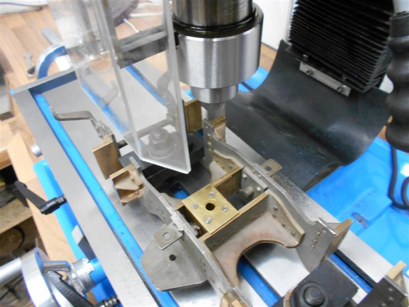 I then spent about half an hour with emery cloth on a parallel giving the insides a bit of a dressing until the axles rode nice and smoothly in the horns. The assembly was then loaded to the kingpin and rested on the pressure pads.  Now I can push the wheels on and get the suspension underway. Thanks for looking in Steve |
|
|
|
Post by springcrocus on Dec 19, 2015 18:13:54 GMT
The components of the smokebox saddle had to be soldered together and I had to decide how to keep the two parts together during the soldering process. It dawned on me that the middle was to be removed after joining and, therefore, the obvious way was to drill a hole though the saddle and fix a cross member across the saddle support with a nut and bolt. The main advantage was that it kept the mass down and I wasn't wasting all my gas heating up clamps. 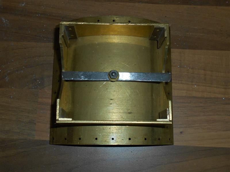 At this point, I undid the clamp and gave the brasswork a really good clean-up and when I was happy with it, I did it all again. Everyone has stressed the importance of cleanliness and I didn't wan't to fail because I was too lazy. I mixed up the flux as I had been shown and put some on the edges of the saddle support before locating the two parts together and clamping down again and, following this, I fluxed the rest of the assembly, placed my pieces of solder into the inner corners and then painted the rest of the flux over the solder. Then I assembled my hearth from my fly-ash blocks and placed the assembly inside.  I was approaching this job with much trepidation but took a deep breath and off I went, directing the flame around the sides and underneath the assembly. After a few minutes the flux had turned to a pinkish slag, bubbling away, but the solder wasn't melting and I started to give the occasional blast of heat over the top. The mild steel clamp turned cherry red but the solder still hadn't melted. At this point, I chickened out and turned off the heat. I decided to mix another load of flux, a little more watery this time, and applied this liberally around the area. A moments thought made me realise that if the solder hadn't melted, then I couldn't have got it hot enough. So this time, I took no prisoners and really blasted the flame into the area and wached the whole assembly start to glow. And then, as if by magic, the solder started to melt at the front and slowly crept along the sides and across the back until it was all gone! I kept the flame going for another ten seconds or so until I was sure the solder had all melted, then turned off the gas, took a picture and then went for a calming cup of tea while it all cooled (too early for engineers lubricant). This photo was taken twenty seconds after removing the heat.  Once it had all cooled down I gave the assembly a good scrub in clean water but had to use an old sciber to get rid of the remaining encrusted flux and had a good hard look to ensure that a decent joint had been made. I'm pleased to say that the solder has flowed evenly throughout and appears to be quite a good joint.  It now needs a really good rub-down to improve the appearance, and I have spent ten minutes or more with emery cloth trying to clean it up but I will give it a few minutes in the shot-blast cabinet later to see if that will speed up matters. It did, and here is the final result. 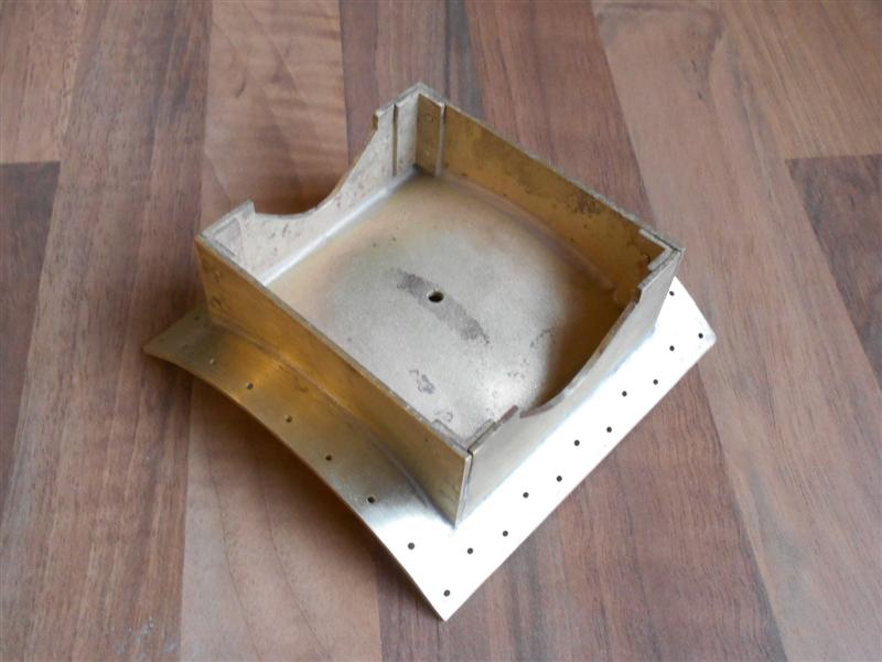 And to finish the job off, I loaded the assembly to my large vice on the mill and removed the central area where the pipes come through. I just need to spot through the frames to mark the boltholes and this part is finished. 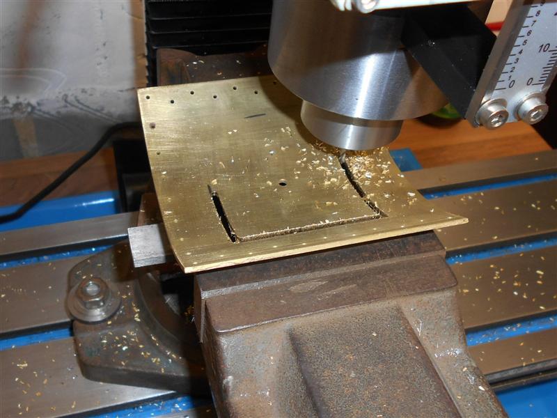  Many of you will have been silver soldering for years but, for me, this was the first time. I've soft-soldered items for over forty years, plus done a bit of stick welding and propane / compressed air brazing in my time but I'm still extremely pleased that this has worked. Thanks to all those people who responded to my thread requesting advice about this and a special thanks to two Johns - John the Pump for his guidance given to me at IWMES and Simplyloco for the practical demonstration he gave me in his workshop back in the spring. If you've never silver soldered before and, like me, have been reluctant to get started I say "Have a go". I think the most important thing I learned was that you need lots of flux, lots of patience and really need to get lots of heat in there. The repetetive use of the word "lots" is deliberate, it's no good pussy-footing around, think BIG and go for it. If I can do it, then anyone can... Still smiling, and thanks for looking in Steve |
|
|
|
Post by Deleted on Dec 19, 2015 19:19:30 GMT
very nice Steve...you sure you've not done this before?......top marks sir..  Pete |
|
johnthepump
Part of the e-furniture
 Building 7 1/4"G Edward Thomas
Posts: 494 
|
Post by johnthepump on Dec 19, 2015 19:54:36 GMT
Nice job Steve,
Having seen the part at the club this morning, For someone who had to rush off home and help the wife with the gardening, you seemed to have sneaked off when the good lady wasn't watching into the workshop and milled out the centre opening.
|
|