|
|
Post by Deleted on Oct 11, 2017 17:42:57 GMT
wow, that was quick Steve... great work as per usual...
Pete
|
|
|
|
Post by springcrocus on Oct 14, 2017 21:45:53 GMT
When I was chatting with John the Pump the other day, I mentioned that I was making the ratchet wheels for the lubricator next and saying that there were no dimensions on the drawing, just a note which states "Purchase ratchet, pawls and spring from Live Steam Services, London SW10". As expected, thirty three years on and the firm no longer exists. John replied, "Oh! It will be one of these, then" and promptly produced an old baccy tin with a few in. It turns out that Arthur Grimmett used to make these for Live Steam Services and John acquired the residue of his stock a long time ago. Julian may remember Arthur making these in his workshop but I'm an Overner and never knew the gentleman. So, along with the angle plate, I blagged one of these from John to use as a pattern. He offered to let me have a couple but I fancied making my own, anyway. That's what this hobby is about. I started by skimming down to 7/16" dia a short length of 1/2" dia bar which I aquired from a local factory and is tough as old boots. It's BS S154 which is equivalent to EN25. I also parted through part-way so that I didn't have an intermittent cut after the teeth were formed. 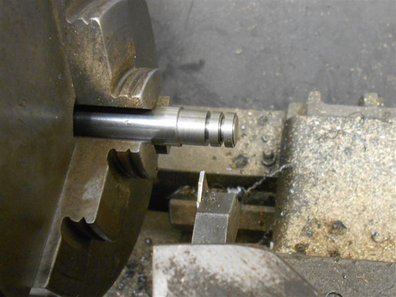 The bar was then transferred to the mill and the teeth cut with a dovetail cutter. The ratchet wheel supplied by John had 35 teeth but I have chosen to make 36 teeth because that is ten degrees, and two turns of the handle on my rotary table. I don't have a dividing head, and John mentioned that Arthur would probably have racked these in a lathe using a detent in a 35-tooth gear wheel.  I went round three times before I was happy with the depth and then returned the bar to the lathe drilled the hole and finished parting them off. 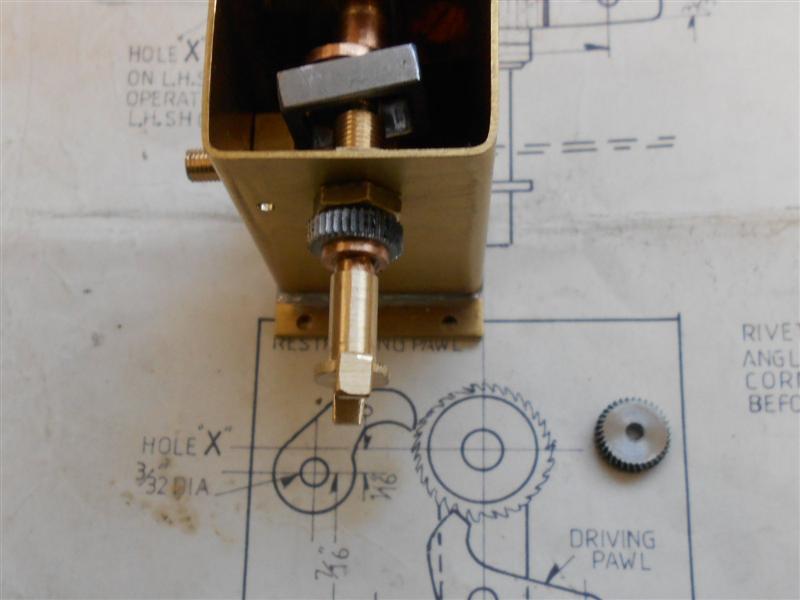 The only thing I'm not to sure about is the tooth form. I only have 45 degree cutters but 60 degree would probably be better. I might remake these if I can pick up a cheap cutter at the Midlands MEX. Thanks for looking in, Steve |
|
|
|
Post by gwr14xx on Oct 15, 2017 7:05:19 GMT
Check out that drawing, Steve. Those pawls and ratchet wheel don't make a matching set (irrespective of the tooth form)!
Regards,
Eddie.
|
|
|
|
Post by Jim on Oct 15, 2017 7:20:32 GMT
It looks like the pawl is upside down so that it won't hold the ratchet for the driving pawl's next stroke but then I'm sure Steve has already worked that out.
Jim
|
|
|
|
Post by springcrocus on Oct 15, 2017 7:52:12 GMT
Thanks, Jim and Eddie, but yes, I took that sketch with a pinch of salt! My pawls will not look anything like those and my springing will be different too. Hope to have something to post up tonight.
Regards, Steve
|
|
|
|
Post by Jim on Oct 15, 2017 10:51:38 GMT
Now you have me thinking Steve that I should make up a ratchet and pawl for my commercial lubricators that came fitted with clutch rollers. Clutch rollers aren't the most reliable.
Jim
|
|
|
|
Post by gwr14xx on Oct 15, 2017 14:03:07 GMT
As bought, my lubricator with roller clutches, was a bit temperamental. Replacing the original shaft with a polished, hardened dowel made the operation much more reliable - however I still had problems getting small increments of rotation - this improved greatly after washing out the clutches and re-lubricating with very thin oil. I can now rely on it 100%. Evidently, in the free wheel direction, the rollers ride up on thick oil (steam oil) then slip in the drive direction over the small movement we are looking for.
Eddie.
|
|
|
|
Post by springcrocus on Oct 15, 2017 18:26:06 GMT
I've chosen to make the lubricator operating levers from 16swg brass because I have a box full of brass offcuts to use up. They would just about come out from 1/2" wide strip but the holes would need to be offset accurately to make it work so I used some 5/8" approx pieces. Although they are left- and right-hand, they are symetrical so I made them as a stacked pair, starting with the holes. These were co-ordinate drilled using the DRO on the mill. 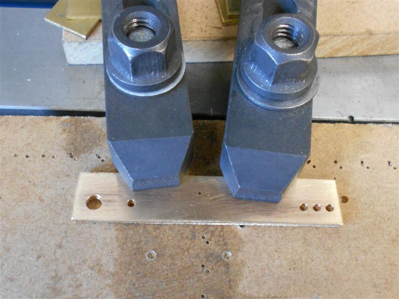 I then set up one of my universal milling fixtures and drilled a matching pair of holes for clamping the work down with. The two levers were bolted down using 8BA bolts and with small washers underneath for some cutter clearance. It only needed a few thou. I then roughed out the maximum dimensions at the head, tail and spring-mount positions. Then I finished the width of the tail end.  Once I had those dimensions correct, I then needed to skew the jig over to form the tapered shape. I don't have any slip gauges but an appropriate sized drill was good enough to provide the correct offset.  I didn't want to unbolt the work from the fixture so had to move the jig in the other direction also, just using a combination of smaller parallel and drill to get the same amount of movement on the other side. Here is the final side just finished.  The rest was just filing and linishing, a filing button being used at the head end and freehand at the bottom. Four pivots were needed and these were made next on the lathe using 3/16" dia mild steel, simple turning and threading, and then it was onto the pawls. I have made these from 1/16" brass as a temporary item to check "proof of principle" and to create a pattern. I will buy some 1/16" ground flat stock at the Midlands MEX and remake them next weekend. First I made the driving pawl and, after a little bit of experimenting, had it working satisfactorily. The spring was made by cutting down from a larger one in the spares box. The basic shape is there but can be tidied up quite a lot more. 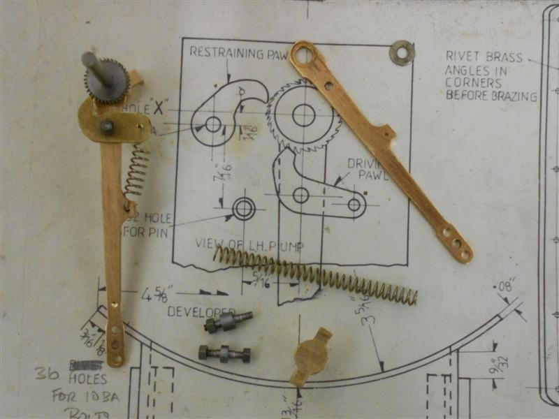 The restraining pawl was similarly made but I needed to make a torsion spring to work with this one, I didn't want another coil spring hanging down the outside. This sits on the shoulder of the pivot and locates against a pin in the pawl and the bush holding the shaft. I've also done a little more shaping to the driving pawl and the lever  Finally, I've assembled all the bits together and am reasonably pleased with it. The ratchet mechanism works as it should and oil comes out of the spout on the down stroke. I still need to make the lids, and I will remake the pawls after the show.   Thanks for looking in, Steve |
|
jma1009
Elder Statesman
  
Posts: 5,922
|
Post by jma1009 on Oct 15, 2017 20:34:06 GMT
Hi Steve,
I also have quite a few of Arthur Grimmett's ratchet wheels - they were case hardened or silver steel hardened. You did well to make your own because those Arthur had left were from a defective batch where there is an unequal spacing at one point on the wheel - or error!
The wheels must be hardened as they otherwise wear badly.
Can I suggest you revisit the brass pawls? They will wear very badly. On the few mechanical lubricators I have made, I used spring steel instead of pawls, and made a few spares at the same time. (Arthur used case hardened steel for the pawls).
Arthur's ratchet wheel teeth were cut by indexing one of the lathes and raking a tool back and forth along the saddle- your dovetail cutter method is considerably superior and is quite excellent.
Cheers,
Julian
|
|
|
|
Post by Jim on Oct 15, 2017 22:29:16 GMT
Hi Julian,
If you re-read Steve's post he makes quite clear the reason why he decided to use 16 SWG brass for the pawls.
Steve is a very experienced machinist and knows exactly what he's doing as he's demonstrated in his very detailed photos of his build. On the other hand if I decide to modify my lubricators your comments have been noted.
Cheers
Jim.
|
|
jma1009
Elder Statesman
  
Posts: 5,922
|
Post by jma1009 on Oct 15, 2017 23:29:21 GMT
Hi Jim,
I do not doubt for one moment Steve is a very experienced machinist.
However, I have had over the years had to repair and replace numerous badly performing and faulty mechanical lubricators for friends and others and club locos although on my own locos except for the first I have used hydrostatic sight feed lubrication.
I know Steve isn't too much interested in the running performance of his loco but I don't think the brass pawls will last very long, and with piston valves a very reliable lubricator is required.
Brass pawls are OK for clock mechanisms when winding up once a week, but totally unsuitable for a miniature locomotive unless stuffed in a glass case!
Cheers,
Julian
|
|
|
|
Post by springcrocus on Oct 16, 2017 6:20:03 GMT
Hi Jim, I do not doubt for one moment Steve is a very experienced machinist. However, I have had over the years had to repair and replace numerous badly performing and faulty mechanical lubricators for friends and others and club locos although on my own locos except for the first I have used hydrostatic sight feed lubrication. I know Steve isn't too much interested in the running performance of his loco but I don't think the brass pawls will last very long, and with piston valves a very reliable lubricator is required. Brass pawls are OK for clock mechanisms when winding up once a week, but totally unsuitable for a miniature locomotive unless stuffed in a glass case! Cheers, Julian Julian, in fairness to Jim, you have not read my post correctly. I believe that Jim was suggesting that you take closer note of the text rather than the pictures. This is from the previous post - Four pivots were needed and these were made next on the lathe using 3/16" dia mild steel, simple turning and threading, and then it was onto the pawls. I have made these from 1/16" brass as a temporary item to check "proof of principle" and to create a pattern. I will buy some 1/16" ground flat stock at the Midlands MEX and remake them next weekend. And from the last paragragph - Finally, I've assembled all the bits together and am reasonably pleased with it. The ratchet mechanism works as it should and oil comes out of the spout on the down stroke. I still need to make the lids, and I will remake the pawls after the showIt has never been my intention to use brass pawls so some of your remarks were superfluous. However, your other point regarding hardening the ratchet has been noted and I may investigate this, thank you. I would like it to work as designed, though. And from the earlier post - and John mentioned that Arthur would probably have racked these in a lathe using a detent in a 35-tooth gear wheel. So John was correct, then, Arthur made his ratchets in the lathe by indexing the head and using a tool in the toolpost to plane the teeth. That is what we call "racking" and why I referred to it as such, so named because the saddle is most commonly driven by winding the pinion along a rack. Regards, Steve |
|
|
|
Post by springcrocus on Oct 21, 2017 17:39:18 GMT
Another of those space-filler jobs whilst waiting for materials was the universal joints for the reversing rod. These have been made from some 1/2" square black bar which is a little oversize and can be milled to size. There are four forks to make, two of which are the same, and a pair of pivot blocks with the pins. After sawing the four billets from the stock, the shoulders and other turning ops were done in the self-centering four-jaw chuck. Concentricity is unimportant because I will mill the sides to size next so I have just loaded the 4-jaw to the 3-jaw chuck for quickness. Note the tape round the 3-jaw chuck! After twice in the past dropping the 4-jaw onto the bedway because I undid the wrong chuck - the keys are the same size - I do this automatically now.  Since the front ends are all the same, I was able to load a backstop behind the chuck and drop each part in and turn all the shoulders to the same settings. The two differing ones had the other sections free-turned.  For the next operation, I loaded the 4-jaw back onto its mounting plate and set it up on the mill, accurately setting the centre to X0,Y0 on the DRO. Each component was loaded in turn and a 3/16" dia slot drill used to rough out the slot using fifty-thou depth of cut at each of the six passes. This was then changed to a 1/4" dia slot drill and the slot finished with a single pass at 5/16" deep. The same tool was then lowered to just touch the packing washer and the outside was then machined all round. This was simply a case of starting at 0.312" on one axis and winding to the same setting on the other side, repeating all the way round. 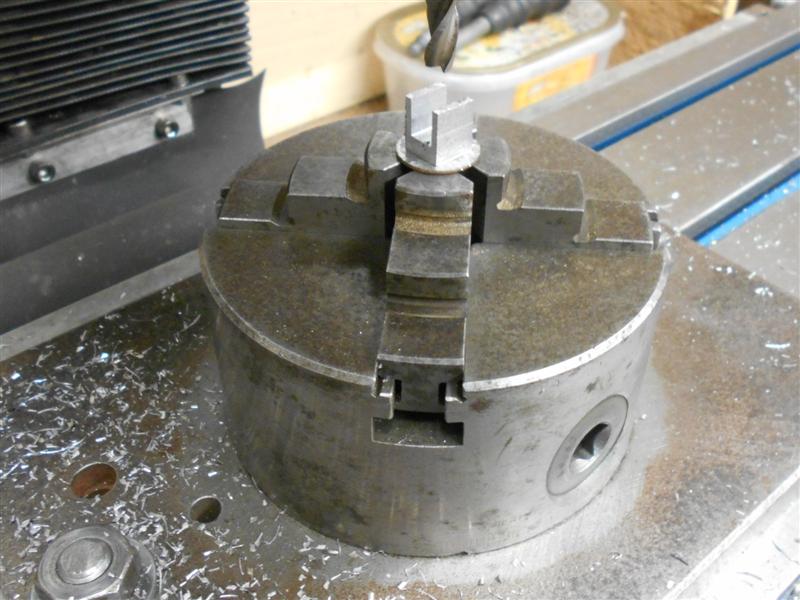 The holes for the pivots were put in using a 1/8" dia slot drill and the shaping of the fork was done freehand on the linisher and with files, a filing button being made to help shape the radius on the end.  The pivot block has been made from 1/4" square mild steel, dressed down to move easily with the space of the forks. I used my small vice with the soft jaws for drilling the holes because I can rest the work on the jaw steps and up against the milled-in end stop. Getting these positioned accurately is quite important or the pivots wont line up properly with the holes in the forks. I don't have 5BA taps, nor any screws, but I have lots of 1/8" Whit screws and a tap so this was used instead.  The screws I've used are slotted brass round-heads which were turned down to a bare 1/8" dia on the head and then cut off with a small amount of thread for fixing into the block. These are all the parts that make up the two UJ's but the shaft can wait till later. For this reason I have not put in the taper pin holes, they will be drilled at assembly time.  And these are the two joints assembled. 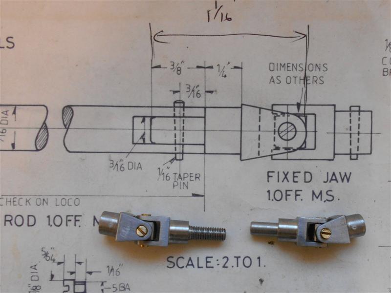 Thanks for looking in, Steve |
|
|
|
Post by springcrocus on Nov 12, 2017 18:21:43 GMT
It's been a while... I've chosen to use the tender filter boxes supplied by Adam Cro for my project and they come as a complete set of castings with a small amount of machining to do. Nuts and bolts are not supplied, nor is the material to make the valves and seats, but a couple of lengths of "O" ring cord are thoughtfully included to assist sealing the filter box to the mounting plate and also some gasket material for the bottom cover along with the filter components. The mounting plates are pre-drilled with the holes for the filter box mounting studs and need a small amount of fettling around the edges as well as tapping but are otherwise finished. The various hole positions on the main casting are pre-dimpled but Adam advises to ignore the top face dimples due to a slight misalignment and, instead, spot through from the mounting plate. 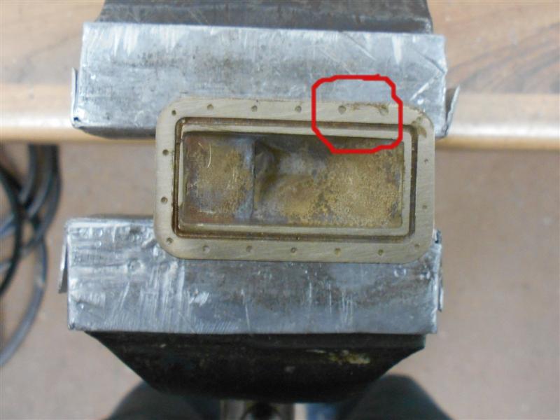 I started by carefully checking over the casting and found that the depth of the "O" ring channel in the top of the main casting was 1.5mm and the "O" ring cord supplied is 1mm diameter, thus leaving just over half a millimeter to clean away from the top face. After fettling the sprue witness from the edge of the casting, I checked how parallel the sides of the boxes were and found a slight taper, making it a little more difficult to hold in the milling vice. To get around this, I wrapped a couple of turns of insulating tape around the body which gives a slight cushioning effect but still allowed mounting in the vice.  The tops of my vice jaws are parallel with the table within tenths of a thou so I was able to rest the flanges on a pair of small parallels but I also wrapped a turn of tape around these packers to ensure they didn't vibrate loose and fall out during cutting. A couple of 10 thou passes running round with a 12mm dia end mill brought them to size, but I could feel the slight abrasiveness of the material on the cutter. It's silicon bronze and I would recommend using a sharp new cutter for this.  A little tip for any who may be unsure about how to measure the depth of narrow grooves. Use a couple of pieces of thin brass sheet, one down the slot and one resting on top, clamp them together and use the step-measurement function of your caliper to get the depth. 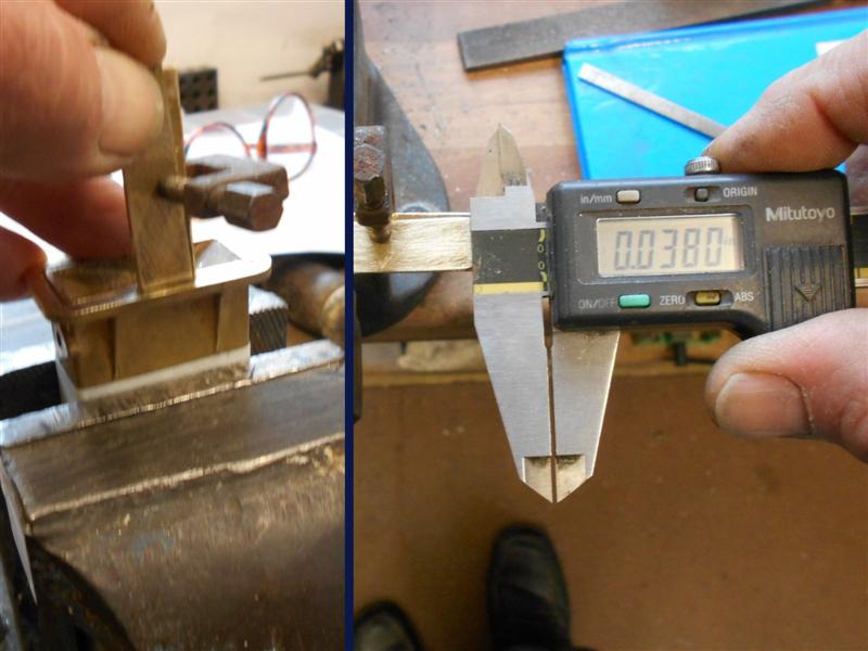 Having this machined face made it relatively simple to hold for subsequent machining operations and the first of these was to clean up the bottom face to allow the lid to seal. One of my general-purpose milling fixtures came in useful here, allowing me to clamp on the underside of the flanges. It only needed a few thou to clean up, and I changed to a 1/4" dia cutter here. Care needs to be taken as one approaches the hinge section.  The fixture was then repositioned and another pair of clamping holes drilled and tapped so that I could hold the filter box vertically, using a square to get it upright. A light skim was taken across the face of the outlet pipe flange mounting point and it says much for the quality of these castings that my five thou depth of cut was more than enough to clean up.  I also chose to centre-drill and drill the three 12BA holes, rather than rely on the dimples, so the outermost dimple was picked up with a point and the DRO zeroed, then offset by half the PCD and re-zeroed. The outlet hole was cleared with a 3/16" slot drill and, using the bolt hole circle formulae, a light touch with the centre-drill at each bolt hole showed that the dimples were exactly where they should be. Based on this, it would be possible to just clean the flange mounting point with a fine file and drill directly into the dimples with confidence. The holes were drilled 1.1mm, slightly over the book size, and left for tapping later. Care needs to be taken on the outermost hole as the centreline is level with the outside face of the casting.  The other side was treated in a similar fashion, a 3/16" dia slot drill clearing the hole and then plunging through the inner wall to create the internal valve seating point. The outer wall was then opened up with a 6mm end mill to take the water valve body.  To finish the filter boxes, the lower hinge brackets and locking clamp brackets were drilled freehand using the cast-in dimples. I have chosen to drill 12BA clear on the front bracket and tap 12BA on the rear bracket and will use a 12BA bolt screwed in from the front and a 12BA locknut on the rear. The various holes were tapped on my new tapping fixture.  The pre-drilled holes in the mounting plates were redrilled at 1.1mm and paired with their respective boxes, clamped to them and spotted through. The boxes were then drilled 1.4mm and the plates tapped 12BA. Adam has kindly consented to me photographing the work sitting on the drawings, as is my normal practice.  Now I need to find some PTFE to make the valve seats, and to make the various small parts that complete these assemblies. That's for next time, though. Thanks for looking in, Steve |
|
|
|
Post by springcrocus on Nov 18, 2017 7:19:48 GMT
A while back I made the filter mounting plate packers which fill the space at the lower curve of the tank.  I didn't go further with at these at the time because I wanted to get the mounting plate holes tapped and matched to the boxes. I have now brought these parts together with a couple of M1.6 countersunk screws and soldered them.  Once they became a single unit, I offered them up to the tank and marked out another pair of fixings to hold them in place using another pair of M1.6 screws while soldering to the tank. A tiny amount of solder has capilliaried up one of the holes but I was able to clean this out quite easily. My little tapping fixture has been a godsend, this time by turning the head round to overhang the base. Tapping the tank could have been fraught with danger but I'm tapping these tiny threads with full confidence now.  To complete these parts, I have drilled the water feed holes into the tank. A pair of blanking gaskets have been made, the filter boxes bolted on and the tank tested for water-tightness. No leaks after twenty four hours so the solder has successfully sealed the mounting plate. I'm using bolts rather than the studs and nuts suggested on the drawing but I'm a bit disappointed with the 12BA bolts that I bought from Blackgates at the Midlands show. When they didn't fit my box spanner, I checked the head size and found they are about ten thou oversize, coming in at 2.5mm. I suppose it's getting harder to find supplies of the old hexagon sizes nowadays. Anyway, I made a new box spanner to fit by drilling a 2.5mm hole in a length of mild steel and whacking a cut-off piece of a 2.5mm Allen key in the end and knocking it about a bit. Not brilliant, but better than nothing and it works. It is also long enough to reach up the back of the filter boxes with ease, my other one would have been too short.  It was just luck that there was a key size available, slightly larger and it wouldn't have worked. Moving on with the rest of the filter components now. Thanks for looking in, Steve |
|
|
|
Post by Cro on Nov 18, 2017 8:15:17 GMT
Good work steve, I like how you made the fill in section and glad it was easy to mount the plate with it. You have done it the way I had in mind but left to the builders imagination!
Any photo of the filter boxes fitted to the tanks?
Look forward to seeing them finished, the slot for the filter can take a bit of fettling once the filter is all soldered up, you may find the filter to come out long and need trimming to suit depending on how well you can clean the top of the slot.
Keep up the good work!
Adam
|
|
|
|
Post by 92220 on Nov 18, 2017 8:54:10 GMT
Hi Steve.
A good write-up on machining the filter boxes. I shall find it very handy when I machine mine! I've found that there are different sizes of hex heads too, even from the same supplier. When I need an odd size hex spanner I look for a suitable allen cap screw and just turn the head down to a minimum diameter, and also the thread down to a smooth minimum diameter. I have a couple of different 12BA socket spanners made that way.
Bob.
|
|
|
|
Post by springcrocus on Nov 19, 2017 18:30:32 GMT
Some of the parts that comprise the filter box assembly come provided and most of these need minimal work. Other parts need to be made and, so far, I've found the drawings to be accurate, complete and reasonably well laid out making the job relatively painless. Unless you are like me, that is. I managed to make hard work of the water outlet fittings and since this is my diary, here is how I made them. Later on, I have included a paragraph explaining how I would have made them if I had stopped to think for a moment. I started by holding on the boss of the flange with the work tight to the jaws and facing off to the finished dimension. Next I centre-drilled and drilled through 11/64" which removed the stub on the back, the intention being to ream 3/16" later. A tiny boring bar was used to create the "O" ring recess, care being taked on the outer diameter as there's not a lot of wall thickness left here.  Next, I put the 3-jaw on the mill and set up to drill the mounting holes. By setting one chuck jaw square to the table, I was able to locate the bolt hole positions over the jaw gaps and drill straight through using the dimensions given. 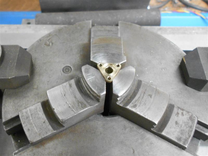 By this point, I'd already worked out that I had made life hard for myself and now had to bolt them to the filter box and use this as a simple fixture to size the water outlet hole.  Of the other cast parts, the bottom cover just needs the sprue removed and the holes for the locking bar drilled. The locking bar needs two holes drilled and the locking handle needs to be drilled and tapped. All these items are dimpled and very easy to finish.  I have also made the swing bolt that holds the lower cover in place. Starting with a piece of 3/16" brass rod, the diameter was reduced to 0.067" for about 3/8" and a 10BA thread cut. This was then parted off with an overall length of 5/8". The eye was made next by milling some of the material away on each side and finished at 0.075" thick x 0.110" wide. Finally, a 1.4mm cross-hole was drilled to enable a 12BA bolt to pass through and the eye was rounded off with files. 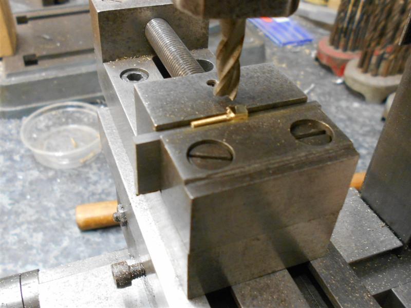 Back to the water outlet fitting. This also has cast-in dimples for the mounting holes and I recommend that these are drilled first. Next I would load the work to the three-jaw chuck holding on the stub provided and start by gently facing off the component. If needed, I would make a little collar to support the back of the flange. Next I would centre-drill and drill 3/16" dia for just over 1/16" deep, any deeper and the part might break away from the stub. With a tiny boring bar, create the "O" ring recess next and finally, start drilling again continuing until the part came away from the stub, remaining on the drill. The wall thickness here is only ten thou so the part is a little delicate. All done in a single visit to the lathe. Finally, a couple of shots of the assemblies so far.   Now I'm getting on with the other bits that need to be made from scratch. Thanks for looking in, Steve |
|
|
|
Post by springcrocus on Nov 28, 2017 22:33:36 GMT
Next up were the parts for the valve and here I've deviated from the drawing, although Adam does say that his drawing is for guidance only and it is for the model engineer to decide how to make this valve. I'm not sure whether it even needs to be functional given that there is a water valve on the locomotive to control flow to the injectors. If not in use, the tender would be empty and the only time I can see the need to operate these valves is if one wishes to clean the filter whilst there is a tank full of water. I have made mine functional but I expect I will open them fully and just leave them there permanently. The flange section has been made from 5/8" diameter brass bar and the 6mm spigot turned for a good fit to the reamed hole in the filter box. The 1/8" Whitworth thread was drilled and tapped and the items parted off. They were then taken to the mill where the four bolt holes were drilled 1.4mm and the square outer form machined. I also put the tiny recess in the flange using a 4mm end mill. I am not putting the "O" ring groove in the boss and will be using some gasket material instead.  The spindle is made from an M8 stainless steel bolt and the 1/8" dia was machined first, for about 1/2" long, followed by the 6mm dia, slightly undersize to fit through the 6mm reamed hole in the filter box, and a 3/32" diameter by 3/32" long section at the front for the handle. 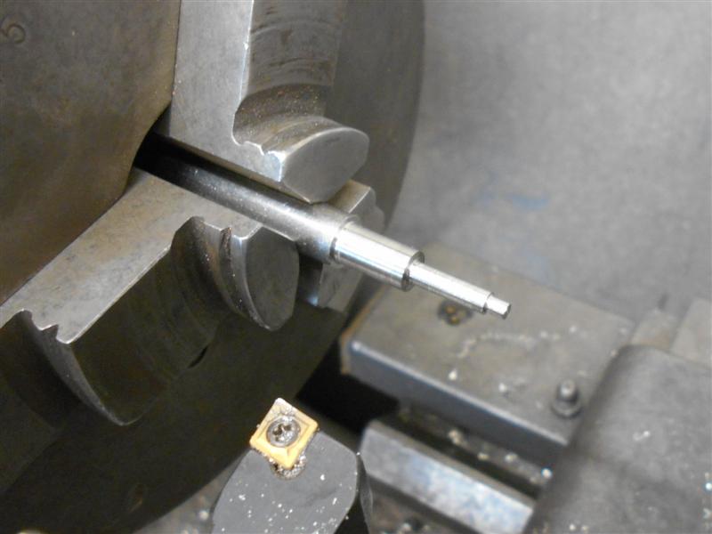 The 1/8" x 40 Whitworth thread was cut next, getting as tight to the shoulder as possible, and finally a 1/16" parting tool was used to first create a 0.120" diameter undercut, then a 1/32" wide x 0.160" retaining lip, and then parted off.  When assembled, there will be a 6mm O/D x 1.5mm c/s "O" ring either side of the flange and these are what create the seal depending on which direction the valve is turned. Unlike sand castings, the surfaces of these filter boxes, including the internal ones, are very smooth and the "O" ring appears to seal very well. The "O" rings in the picture are a little bigger and will be changed. 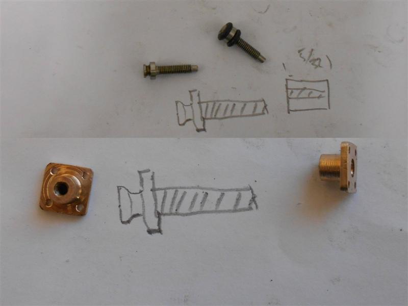 Two pairs of brass stampings are included together with the filter gauzes and the instruction to solder these parts together and finishing with a maximum thickness. I didn't want to take the risk of soldering these parts and filling the gauze with solder so I made a new pair of carriers for the gauze from some 26 swg brass sheet. These were cut out a little over twice the required length and bent in half and squashed flat in the bench vice with a sacrificial piece between the leaves. These were them milled to the same width as the supplied leaves. 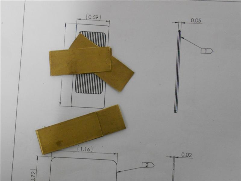 Then they were set up on the mill in a small vice and a 1/8" diameter pilot hole drilled in one corner.  The open end of the leaves were clamped with a mole-grip (the only thing I could find that didn't foul the workspace) to stop them springing apart during machining and a 1/8" end mill was used to remove the centre section. It pays to work away from the stop while the material is at maximum strength and back towards the stop when it's most vunerable to collapse.   Even held with the mole grips, it can be seen how the material has flexed away from the cutter during machining.  The parts were deburred all round and the sacrificial centre leaf discarded, leaving a space for the gauze. Finally, they were trimmed to length and set into the guideways in the filter boxes, a small amount of fettling being needed to clear a couple of bumps in the channels.  If I need to change the gauze at a later date, the carrier just slides out and the old gauze can be discarded and a replacement fitted with ease. Apart from making the small square handles and cutting the gaskets, that is the filter boxes completed. However, I am still doing a few small jobs on the tank and chassis at present so will refrain from fitting the boxes until these are complete. These boxes are highly vunerable to damage while the tank is unmounted from the chassis. Pictures after re-assembly. Thanks for looking in, Steve |
|
|
|
Post by Cro on Nov 29, 2017 11:42:28 GMT
Steve,
They look great! Thanks for the great write up. I like the little changes to the valve and will go back and have another look at that when I get some time.
Look forward to seeing them sat on the bottom of the tank.
Adam
|
|