|
|
Post by springcrocus on Jun 4, 2019 6:04:11 GMT
The sanding gear is non-functional and made from various bits and pieces. The sand pipe is from 3/32" dia brass tube, the dummy steam line from copper wire taken from some 1.5mm twin and earth cable, the combining nozzle and nut from 1/4" hex brass and the bracket from 16 swg brass sheet offcuts. The machining of these parts is mostly straightforward and needs little explanation.  However, the drawing does show a forty-eight thou hole at 30 degrees in the combining nozzle to fit the steam pipe to and for this I made a simple fixture to screw the nozzle into. A 1/4" x 40 hole was tapped in a piece of hexagon brass and the hexagon rotated round and held in a vice. This allowed the nozzle to be screwed in, a tiny flat filed where the hole was to be and then centre-drilled and drilled 1.5mm.  The 3/32" dia pipes were bent freehand using a bending spring and the various parts were soldered together with silver-bearing soft solder.    Thanks for looking in, Steve |
|
|
|
Post by springcrocus on Jun 5, 2019 18:28:08 GMT
I emailed five companies for quotes for my boiler material and only one replied, although a second claimed to have difficulty contacting me. So I emailed the other four companies again and had three more replies. Easy Metals still didn't respond so I assume they cant be bothered with small orders (if you can call a starting guestimate of £500 small). The best quote was from Buy Metal Online in Newcastle, who had plenty of offcuts to trawl through and were able to offer a very keen price. Arctic Metals came in with a pretty good price, too. Worth checking out both if you are building a copper boiler. I won't say how much I paid but it is significantly less than what I expected. I think they made a mistake, told them so and offered them chance to requote but they were comfortable with their price and a deal was struck, ten guillotined pieces amounting to about nine square feet and delivered three working days after ordering.  The bending rolls have been borrowed from the club and the boilerwork is now underway. I'm a bit apprehensive of this, it's way out of my comfort zone. Luckily, however, I will have John and the Pumphouse team to beg assistance from if I get in a muddle. Steve |
|
|
|
Post by springcrocus on Jun 5, 2019 21:45:15 GMT
The bases of the dummy cylinder release valves were made in a single operation from 3/8" hex brass bar, turning the large diameter first, adding the chamfer and then forming the 3/32" dia locating spigot with the parting tool. The parting tool was then moved along a further 1/16" and the component parted off. I made the body from 5/16" diameter brass bar as a bullet shape only, leaving the drilling for later. 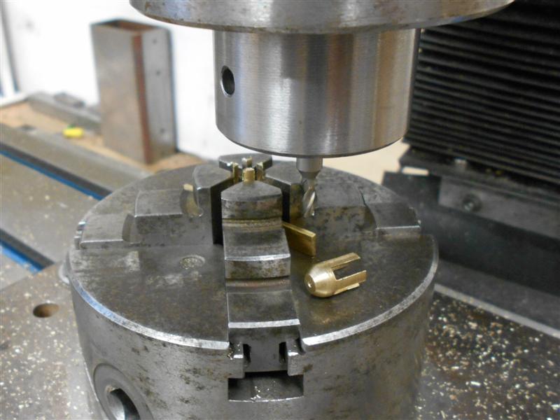 Moving to the mill, I set up the self-centering 4-jaw chuck on the table and set the exact centre on the DRO. The bodies were then inserted nose down and the 13/64" diameter hole drilled to depth. Because I have changed the design slightly, I also drilled a 1.8mm hole through instead of the 1.4mm for 10BA. The next operation was to form the four slots and this was done with a 1/8" diameter endmill, passing back and forth on the respective centre-lines. This shows the reason for the choice of the 4-jaw chuck. 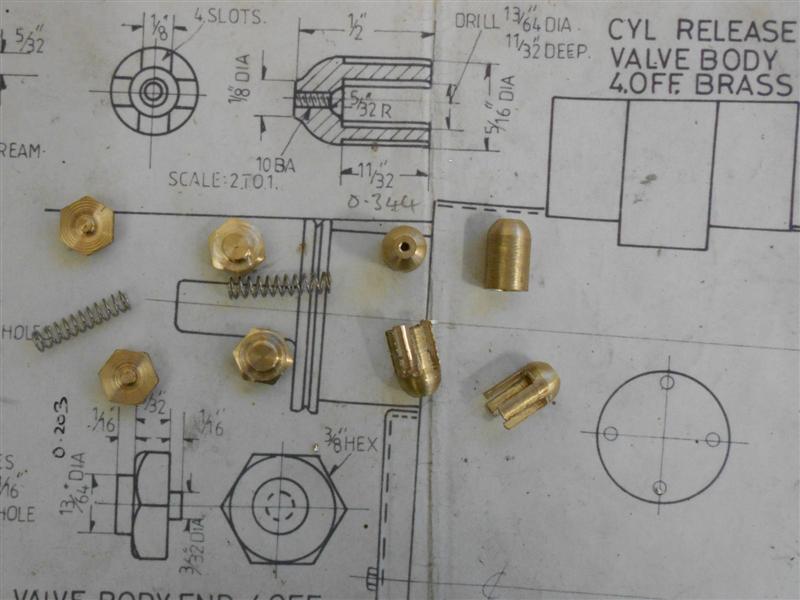 A small drill chuck was then set in the 4-jaw and the bases drilled 1.4mm, holding on the 3/32" spigot. The 4-jaw chuck jaws wouldn't close down far enough to hold the parts. They were then tapped 10 BA freehand using my small tapping fixture. 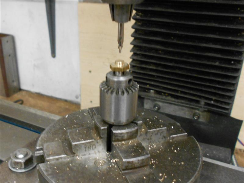 A pair of pen springs were cut in half and the three components brought together with a 10 BA bolt through the centre. 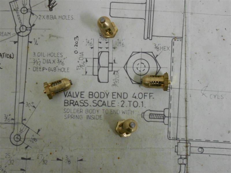 These will be soldered to the cylinder front and rear covers once they have been made. Thanks for looking in, Steve |
|
|
|
Post by springcrocus on Jun 7, 2019 17:07:36 GMT
The valve bobbins are made of cast iron to match the valve liners although the drawing calls for stainless steel if using gunmetal liners. I made both bobbins from the same stick of meehanite using the centre section for holding in the chuck. I started by cleaning up the front face and roughing out the O/D to thirty thou oversize. 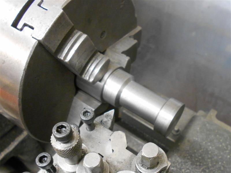 Next I machined the centre reccess to finish diameter with a wide parting tool and accurately finished the front shoulder dimension to 0.312" and the gap to 1.375". Because I am using 6mm for the valve spindles, rather than 7/32", I then drilled and reamed the through-hole at 1/4" diameter. After turning round and repeating for the opposite end, I then parted off the two valves a few thou over-length and finally faced them to exactly 2.000". A 1/4" diameter mandrel was made and left in the chuck to ensure concentricity and each bobbin loaded in turn.  The O/D was then slowly reduced until just a couple of thou above finished size and then slowly polished down with fine emery cloth until they were just starting to go in the valve bore. Then I used the hone in each bore, polishing until I had a slightly stiff, sliding fit. Each bobbin was matched to it's respective cylinder and marked to ensure they didn't get mixed up. The two bores are about half a thou different to each other.  They have been loaded to their respective rods and will be adjusted for position at the appropriate time.  I was reluctant to post this because everybody will be wanting to tell me that they won't work, that they will leak, that they need PTFE rings or cast iron rings etc. but they would be missing the point. I have made what is shown on the drawing and I have tried to make it as accurate as possible. They can easily be remade if they don't come up to scratch at running time but that is for the future. They must have worked for the designer but if they are not going to work for me I will find it out for myself and fix it at the appropriate time. What I'm not going to do is fix it before it's broken! Thanks for looking in, Steve |
|
oldnorton
Statesman
 5" gauge LMS enthusiast
Posts: 696
|
Post by oldnorton on Jun 8, 2019 9:24:57 GMT
Steve,
I would expect that the piston valve heads will work just fine if they are a very close fit in an absolutely true bore. Don Young advocated a very tight fit that was "hammered through" a few times with molyslip until it all ran smooth. An air pressure test when assembled with the bobbins dead centre will tell you how much is leaking past (a faint whisper or a big blow).
I didn't find it easy to get a reasonable seal on my Britannia last month. The newly made cast iron piston rings leaked like billy-oh and I found that the heat treatment had made them out of round by just a few thou. I now have PTFE thin tyres that seal at 25 degC, but only partly at 18 degC (!!)
If you do make different bobbins then it might be worth looking at the head width of 0.312" that is on the Perrier drawing. This gives far too much inlet steam lead. A figure of 0.355", still with the 2" overall, gives exactly zero inlet steam lead. I did notice from Jim's photos that he altered this dimension on his Britannia. But there must have been a hundred Britannias made with Perrier's 0.312" dimension and presumably they all ran.
Hope these comments are helpful to your build and not an intrusion. I have also posted this as a separate thread in case anyone wants to pick-up on what I have said. Please do feel free.
Norm
|
|
|
|
Post by springcrocus on Jun 9, 2019 6:31:30 GMT
I made the former for the outer wrapper of the firebox using a couple of lengths cut from a railway sleeper, screwed together and then hand-sawn to form the tapered shape. It's a big box and needed a few hours work to produce. A 2-hour workout in the gym would have been less tiring. Cardboard templates were made of the top of the firebox by tracing from the drawing, marked onto the former and then profiled with a plane and orbital sander.  The angles for the backhead and the bottom of the box were marked onto the former next. A large piece of paper was then placed over the former and the lines transferred to the paper, giving me a flat layout, or development, of the wrapper. This came out at 608mm x 280mm, quite a big lump of copper.  The former for the firebox inner was made in a similar fashion but with a separate piece at the front for the combustion chamber.  This was turned to 5.1/2" diameter and then screwed to the inner former, aligned with the boiler centre-line. One of the pictures shows a polished carbide tip in use. These are super-sharp and work well turning wood.  This time, the development had to include the wrap-around section for the combustion chamber which is joined with a strap at the bottom. For this the copper needs to be 462mm x 280mm.   Steve |
|
|
|
Post by Deleted on Jun 9, 2019 9:06:27 GMT
Excellent work Steve....  Pete |
|
|
|
Post by a3lner on Jun 10, 2019 6:04:16 GMT
Looking good Steve 😃
Tom
|
|
|
|
Post by springcrocus on Jun 10, 2019 18:42:17 GMT
The eccentric bearing has a back plate and front cover, required because this is the only part of the motion that constantly rotates a full circle whereas all the other parts are reciprocating. I made the front "top hat" from some 1" dia aluminium alloy, facing and turning the outside forms, then parting off at finished length. The parts were then loaded to the chuck on the mill table and the centre removed with a succession of slot drills. The 10BA clearance holes were also drilled at the 0, 120 and 240 degree positions. Finally, the fixture that I used to mill the shape on the ends of the eccentric rods was reloaded to the chuck and the caps bolted on. A 1/4" dia end mill was used to remove the material to create the inner form, rotating the table from 60 degrees to plus and minus 33 degrees, similarly at 120 and 240. 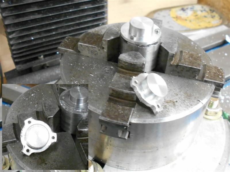 The back plates were made from 16swg brass offcuts, a 3/8" diameter hole drilled and reamed in each one. These were than loaded to a mandrel in the lathe and turned to 0.970" dia, the outer size over the bosses. The complete assembly was taken to the mill and loaded into the chuck with the rotary table set at 0 degrees. 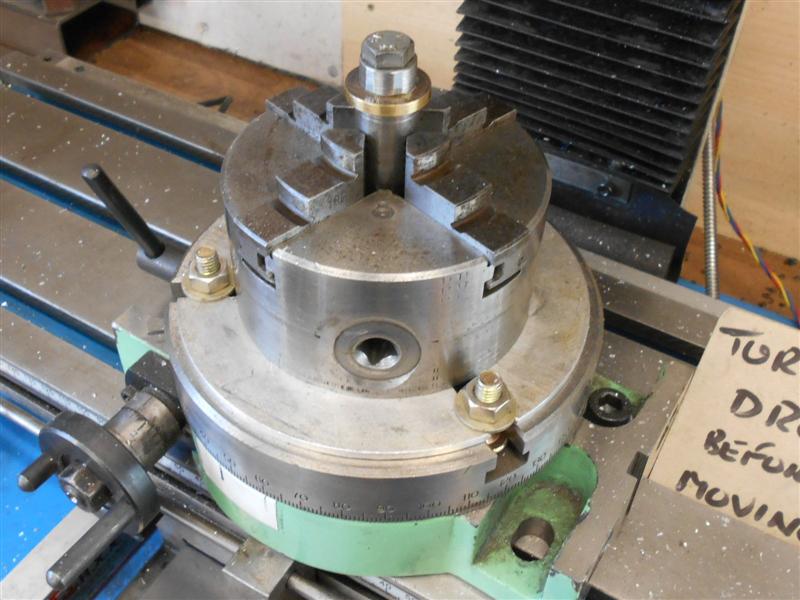 The three holes were then drilled at 1.4mm - 10BA core size - and the inner form milled as before, although I found that I needed to plunge-cut to remove most of the material, finishing by rotating the table. 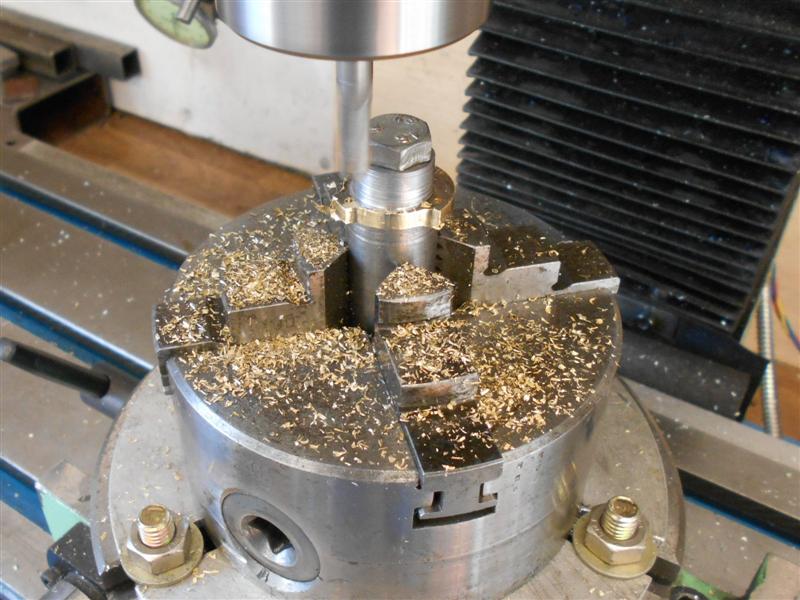 To finish, the components were bolted together and the outside form of the bosses made using sanding drums in the Dremell 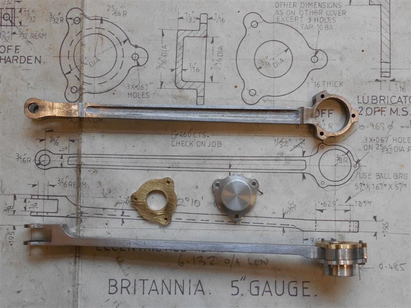 And, finally, mounted on the locomotive  The drawing calls for aluminium and, of course, without thinking I just followed the drawing. However, every picture of a Brit that I have seen appears to show a gold-coloured bearing cover and I shall remake them in brass a little later on. Now I've had some practice, the next pair should be better looking anyway. Thanks for looking in, Steve |
|
|
|
Post by springcrocus on Jun 11, 2019 22:12:19 GMT
Sorry, I'm dancing around a little, intermingling the boiler build with the final stages of the chassis. The various flanging plates have been made from an offcut of 40mm laminated oak kitchen worktop. The shapes were marked out, allowing for any bends in the plates, then cut with a jigsaw. The backhead plate needed some extra shaping and this was done on the mill. Because of it's size different workholding methods were needed; the first angle was created by clamping direct to the table, the other two by screwing a piece of box-section mild steel to the reverse and holding in the tilt-and-turn vice. Here, the clamps and front bracket stop the workpiece rolling forward, the angle being set by choosing the correct diameters for the jacking bars. Tapered wedges assist the clamping.   The combustion chamber front plate and the firebox backplate were made in a similar manner to the backhead plate. The front tubeplate former has been made as a double-duty item with the rear tube plate on the rear. If this doesnt work, I will need to split them in two.   The front throat plate was the largest of the formers and the most challenging to make because the drawing section is staggered. Once finshed, I noticed that the milling cutter and collet in the mill had tarnished overnight where I failed to clean down properly. There must be something in the oak that affects the steel - probably tannin - so I must be more thorough in cleaning up afterwards when machining hardwoods.   Steve |
|
|
|
Post by springcrocus on Jun 13, 2019 6:27:13 GMT
Firstly, thanks to all those who have continued to follow the diary, and who have indicated approval with "likes". The relatively high view-count is heartening and gives me the encouragement to follow this record through to the end. Thanks also to Norm (oldnorton) for showing the way regarding taking an interesting point away to another thread for further discussion. I think it keeps the diary far more readable. Whilst setting up the motion a few neccessary modifications became evident and I've brought them all together in a single post. The first concerns the expansion link brackets. The expansion links foul the brackets at full throw and extra material needed to be removed to accomodate this.   The next was the clearance for the expansion link tailpin. For this, short pins were made and retained in the expansion link by drilling and tapping M3, using a pair of grub screws to retain the pins. The downside to this is that any wear will now be on the eccentric rod eyes rather than the tailpin bush but I will live with this for now. A slightly larger-diameter pin and a sloppier bush would probably have been the way forward.   Finally, the valve guide clearances needed adjusting. Pushing the loco back and forth along the bench with the reverser in mid-gear, I noticed that the clearances of the die blocks at each end of the valve guide were different when on opposite dead-centres. On the driver's side the gap between the die block and the front endstop was 0.146" and at the other it was 0.122". To get these readings more equal, the combination link was removed and a small set put in it to compensate. On the fireman's side, it was the other way round, the front clearance was 0.101" and the back clearance 0.165". For this side, it was easier to move the whole valve guide nearer to the cylinder. This was achieved by taking the valve guide to the 4-jaw chuck and facing another thirty two thou off the rear face.  These size differences were caused by differences in the valve guide lengths in the one instance, and the fact that I had inadvertently managed to bend the combination rod at some point by not keeping my eye on the ball when rolling the loco back and forth on the bench. Steve |
|
|
|
Post by ettingtonliam on Jun 13, 2019 7:16:39 GMT
Oak contains tannic acid, which is probably what caused your tarnishing. If you remove old unplated steel screws from oak furniture, chances are they will be corroded, which is why best practice with oak is to use brass screws. When oak was commonly used structurally, any bolt holes were drilled slightly undersized, and a red hot iron bar pushed through the hole to char the inside and kill the acid.
|
|
JonL
Elder Statesman
 WWSME (Wiltshire)
Posts: 2,912
|
Post by JonL on Jun 13, 2019 21:06:23 GMT
I realise you are making a 5" gauge whilst I fiddle with a 3.5", but I still find this thread interesting and informative. If it helps your motivation I find this post very useful indeed and am enjoying watching your locomotive come together. Keep it up!
|
|
|
|
Post by keith1500 on Jun 13, 2019 21:33:31 GMT
Ditto
Please be encouraged to continue. Good photos etc make for an interesting read.
Thank you
|
|
|
|
Post by springcrocus on Jun 14, 2019 16:24:58 GMT
After bolting the cylinders on for what is, I hope, the final time I set about getting the length of the piston rods correct. I dismantled the end covers from the cylinders and removed the rings from the pistons to make it easier to work. I also found it easier to remove the slide bars and slide bar brackets leaving the crossheads floating. The driver's side piston rod was about seventy thou too long and causing fouling of the front cover so this was removed on the mill. I didn't want to break down the chuck that was on the table so used it as a vice instead. Another use for a 4-jaw chuck!  After checking that there was equal clearance at both ends of the cylinder, I removed the crosshead from the con rod and, with the piston rod located in the bore, the two parts were cross-drilled and reamed to accept a 3/32" dia taper pin. The fireman's side was much the same and it's probably where I made the crossheads to my own design rather than follow the drawing. On reassembly, I found that one of the slide bar brackets was still a smidgeon too low and putting undue pressure on the piston rod so the mounting holes in the frames were opened up a little more and the bracket clamped up tight where it wanted to naturally sit.  It all slides as smooth as silk now. Steve |
|
|
|
Post by springcrocus on Jun 16, 2019 6:16:45 GMT
The drawing shows a develpment of the boiler shell and the first thing to say is that the dimensions are rubbish. The 19.9/16" dimension should be 19.1/4" and the 21.3/8" dimension should be 20.3/4". These dimensions were duly marked out on the blank sheet and the waste removed. I don't have a bandsaw but a good-quality blade in my jigsaw worked fine, brushing on some suds to help lubricate the cut and keep it cool. The edges were then filed to a good finish with particular care to the edges forming the bottom join.  Next, it was annealed in my temporary home-made kiln / hearth using a propane cyclone burner because it doesn't get starved of air as easily as normal burners. However, it's a big lump and took ages to get hot.  I had to let it cool naturally as I don't have a village pond nearby, then it was into the rollers and much heaving and grunting as the barrel was rolled.  Halfway through I removed the workpiece for another heat-up before finishing the roll.  It looks easy but is actually quite hard work. Aside from the waiting time whilst cooling, I must have spent a good two to three hours on it. I then spent another hour or so teasing it to the final shape, the two flats at each end of the roll being hammered to shape. I made an anvil from an old acetylene gas bottle that I scrounged from the local gas stockist but I was hoping to find a length of old telegraph pole.  I also had to file out some more material from the join to get the sizes at the ends correct and I made a couple of plugs from the oak offcuts to fit each end, rather than using the tube plates. Just a little more to be filed out at the front for a really tight fit.   After that, the next job will be to make and fit the strap prior to silver-soldering. Steve |
|
|
|
Post by springcrocus on Jun 18, 2019 8:03:48 GMT
Whilst making the cylinder valve liners and the bobbins, I deliberately made sure that the length dimensions were as accurate as I could make them. Because of this, I was able to make the preliminary valve settings quite easily. Working on one side at a time, I first screwed in the valve stem, without the valve bobbin, into the valve crosshead about half way and locked its position. Next, I set the loco on back dead centre using the wheel tram and accurately measured from the front of the valve liner to the front of the valve stem, noting the dimension. The loco was than rolled forward to the front dead centre position and the measurement repeated. Adam mentioned making a means of adjusting the spindle easily. In my case, I chose to hacksaw a screwdriver slot.  Taking the average of these two measurements gives the exact mid-point of the valve travel and the loco was rolled backwards until exactly at this midpoint. Because I know the overall length of the valve liner and the length of the bobbin, I could calculate the position of the front of the bobbin relative to the front of the valve stem. Without moving the loco, the valve stem was then removed and the locknuts and bobbin loaded on. After much fiddling around, I managed to get to the point where the bobbin could move radially about the valve stem but with only about a thou end-float and the distance from the front of the bobbin to the front of the valve stem within a couple of thou of the calculated dimension.  The valve assembly was then reloaded to the cylinder and the valve stem screwed into the valve crosshead until the bobbin measured 1" from the front of the valve liner. The valve stem was then locked in this position and the valve should now be at the correct position. This procedure was then repeated on the other side. I don't know whether this is the correct way to set the valves but, as the short video I posted some while ago shows, after lashing up a temporary air supply, the loco worked "straight out of the box" so to speak. It's all very tight and a bit jerky at the moment but I am going to set up a more substantial air supply and set it running for a few hours to try and run it in. After that, if the valves need tweaking, the motion should run a little more freely. Thanks for looking in, Steve |
|
|
|
Post by springcrocus on Jun 20, 2019 6:26:15 GMT
I chose to make the rear tube plate first because it is one of the smallest items and not too expensive to replace if I messed it up.The plate was cut to shape from a 129mm x 178mm piece of 1/8" copper sheet. After that, the plate was annealed and the forming began. I started with a rubber mallet but changed to a steel hammer and hardwood drift after a short while. I couldn't get enough movement with the rubber mallet, or maybe I'm just too impatient.  I found that a backing piece was essential to stop the flat area deforming. It took me four further heat-ups to get the plate fully formed.  Then I clamped it to the mill table and trimmed the flange height to half an inch. I'm not going to put the holes in until I have sourced the superheater flue tubes in case I get the hole size wrong.  The next part I made was the front tube plate, marking out the 7" dia circle on the 178mm guillotined blank. Then I hacksawed away the waste and followed with a first heat-up to bright red and quenching in water to get the blank nice and malleable.  As before, the flange was slowly formed around the former, working until resistance was felt. The workpiece was then reheated and quenched before forming continued, this cycle of working and then annealing continuing until complete. It took four reheats before I finished.  The flange was trimmed to 7/16" long in the lathe using a polished carbide for the cut.  Thanks for looking in, Steve |
|
|
|
Post by ettingtonliam on Jun 20, 2019 6:55:48 GMT
The rubber mallet didn't do it for me on 1/8" plate either. Alec Farmer recommended the use of a planishing hammer for flanging work, so I got one off ebay, and that seemed to work fine. Probably too late for you now.
|
|
|
|
Post by Deleted on Jun 20, 2019 8:02:24 GMT
That looks excellent Steve, great work sir...
Pete
|
|


