|
|
Post by Cro on Jun 11, 2015 12:55:37 GMT
Steve, Stick to playing the piano mate, you doin' fine. To quote the late, great Les Dawson, you're playing all the right notes, just not always in the right order! Joan, you know jack **** about bearings. Have a nice day y'all! NickM He's certainly playing the right notes and I can't hear anything wrong with the order! Adam |
|
|
|
Post by springcrocus on Jun 11, 2015 16:04:24 GMT
Thank you, Gentlemen, for your support and kind words.
I don't wish to get embroiled in any arguments and I certainly don't discourage comment but I carefully chose the title " ...DIARY" because I was always under the impression that a diary was a persons written record of PAST events. Therefore, discussion about whether the design is good, bad or indifferent is rather pointless.
Anyway, I shall continue to post in the diary about once a week, I just hope I'm not boring the socks off too many of you.
Steve
|
|
|
|
Post by Cro on Jun 11, 2015 17:17:14 GMT
I never kept a diary.....my bad! Lastly, isn't it a Perrier Brit not lbsc?
Looking forward to next update, must be nearing the wheels soon and it's always interesting to see how others do them!
Adam
|
|
|
|
Post by Jim on Jun 11, 2015 23:24:39 GMT
Hi Steve, As another Britannia builder I follow your posts with great interest and enjoyment. From a personal perspective I think many folk forget that our models are our personal creations rather like someone painting a picture. Some of us may want to go fine scale to create a perfect miniature of the full size while others get great pleasure from building a more utilitarian model that becomes the club's 'work horse'. I think you are spot on to ignore the ill considered comments so keep posting Steve it's a most informative diary you're creating.  Jim |
|
|
|
Post by alanstepney on Jun 12, 2015 15:18:26 GMT
This is a "build Diary" and tells how one person built a specific engine.
Let keep it to that.
If anyone feels they can do better, then do so and produce your own build diary.
If anyone feels that they are a better designer than LBSC, then design over 100 locos, build most of them, get them published and receive some awards.
|
|
|
|
Post by springcrocus on Jun 13, 2015 6:22:29 GMT
There's been a few changes here that I can see - thanks to all for getting it back on track (no pun intended  ) Steve |
|
|
|
Post by Cro on Jun 13, 2015 6:49:33 GMT
There's something called Private Messages that help a lot to fix background disconnections. Steve, are you listening? Joan he has clearly blocked you for a reason, just honour his decision and stop antagonising the situation and move on because the more posts you create in spite of what people are saying is only making this whole situation worse and peoples feelings towards you worse and then you complain that people block you? I know we love going round and round in circles with our trains but this is not a club track and it's not an enjoyable lap we keep going round! Adam |
|
|
|
Post by springcrocus on Jun 13, 2015 12:31:47 GMT
The axles are just a bit of simple turning. I made them from some 3/4" diameter EN8DM material that we always had in stock. 40-ton tensile so tough but nice to machine because of the slightly higher level of Manganese in it. First, I just roughed them out using the 3-jaw chuck and a back-stop, leaving about fifteen thou to come off the two journals but finishing them to length at this visit.  After that, I set them up as shown to finish the diameters. A purist would probably use centres at both ends and a driving dog but my chuck runs true enough to grip one end and run the other in a live centre. Having a shoulder for the chuck jaws to push on also helps when it comes to winding up the centre otherwise the work would probably creep backwards as the cut came on. I also changed over to a bit of HSS tooling here, partly because my rhomboid tool wouldn't fit anyway. It's also easier to take tiny cuts with HSS and we are talking a few tenths tolerance here.  The pictures make the finish look rubbish but it's a trick of the light, they are actually very smooth.  Anyway, pretty boring stuff, sorry about that, but the main aim of the diary is to cover every single part of the build over it's lifetime. Thanks for looking in Steve |
|
|
|
Post by ejparrott on Jun 13, 2015 14:43:39 GMT
I don't worry overly much about the axles. I hold the material in a collet chuck when small enough and turn both ends off that. MY tyres on the other hand I don't finish, not until they are shrunk on, then and only then do I finish turn the profiles, and when I do, I sometimes use the collect chuck again (especially outside crank or bearing axles) and sometimes use two centres and a drive pin.
|
|
|
|
Post by springcrocus on Jun 19, 2015 22:30:44 GMT
The main job of the axle box covers is to control side-to-side movement of the axle where the outer edges bear against the gunmetal horns, although they are handy for holding the bearing firmly in the axle box. I have made the covers from billets sawn from 2.3/8" dia mild steel bar although gunmetal casting are available. I don't see the point since the horns are made of gunmetal and similar metals often fret if rubbed together. After deburring the edges and mounting them to soft jaws I first faced them off to clean up, followed by drilling and boring the 25/32" diameter axle clearance hole and clearing the bearing relief area still using the boring bar. I did all six like this before reversing them in a separate operation and facing the back, or outside as it will become, and forming the 1.1/8" diameter x 1/64" deep relief on that side. Finally, they all went back into the soft jaws for a third operation which was to turn the main axle box locating spigot which I made a thou or so smaller than the bearing diameter.  After that, they were sawn and milled an edge at a time to arrive at finished size, just holding vertically in a vice or, in my case, bolted to a faceplate and rotating round using a square to set the position. Accuracy is not important here, it's the axlebox with it's bearing depth that controls everything.  Once they were all milled to size the only things left to do were to mark out and drill the bolt holes...  ... and then pair each one up with an axlebox, spot through and finally drill and tap the axleboxes.  These are now ready for assembling with the bearings and axles although I will have to remember to make the pump eccentric for the centre axle first and slide it on before pressing the bearings on. Thanks for looking in Steve |
|
|
|
Post by springcrocus on Jun 27, 2015 18:28:47 GMT
With the pump eccentric my first instinct was to face, turn and form the groove as one operation followed by loading to the four-jaw independant chuck and machining the bore and boss as a second operation. However, I felt that I would likely damage the shoulders of the eccentric with the amount of work needed on the second op so I decided to do it in three stages instead. Starting with a 1" long billet of 2" diameter mild steel, I faced the back to clean up and skimmed the O/D to 1.7/8" diameter by 1/2" long, then turned it round and faced it to 7/8" overall length. This meant I could load the billet to the four-jaw chuck and tighten it up firmly with little risk of damage. Next, I marked out the middle of the offset and centre-popped it followed by loading to the four-jaw chuck and, since I didn't need a high level of accuracy here, true-ing up with a hard centre in the tailstock. Then it was a straight-forward matter to drill and bore the 3/4" diameter hole and turn the boss to 1.1/4" diameter by 7/16" long. I don't have a 3/4" reamer so boring would have to do. It's locked to the centre axle with a couple of grub screws, anyway, which will pull it square to the shaft. The last job on the lathe was to hold the boss in the four-jaw chuck and true up the outside before machining the bearing area of the eccentric. For this I used a parting tool slightly modified with a notch ground out of the middle. I did, however, play around with two saddle stops to control the width as I didn't want the fit to be too sloppy.   To finish, the eccentric needs to have the two drilled and tapped holes in the boss, which I have made M6 because I have grub screws that size. I decided to mount a piece of 3/4" diameter bar in a vice and clamp it on the drill table.   To make the strap, I cut some blanks from a section of 5/16" brass plate. To get the size, I placed some tracing paper over the drawing and roughly sketched round the form and then fixed this to the plate with spray-mount adhesive.  The two pieces were then roughly cut out and the two mating faces linished flat followed by milling the clamping faces at each end of the two halves. I also formed the rest of the outside shape with the linisher, files and my dremel. Next I marked out the screw holes and drilled them 1/8" to be a good clearance for the 6BA bolts and also milled the slot to take the coupling arm and drilled the three rivet holes. The two halves were then nut and bolted together and put into the four-jaw independent chuck on the lathe and the 1.11/16" diameter bore machined out to size.  I found that a very light touch was neccessary when tightening the jaws as I could see the whole thing deforming. After getting to within ten thou of finish size, I loosened the grip right off and gingerly took a couple of final tiny cuts. This is not the best way of doing this job! Clamped to a faceplate might have been the smarter option. 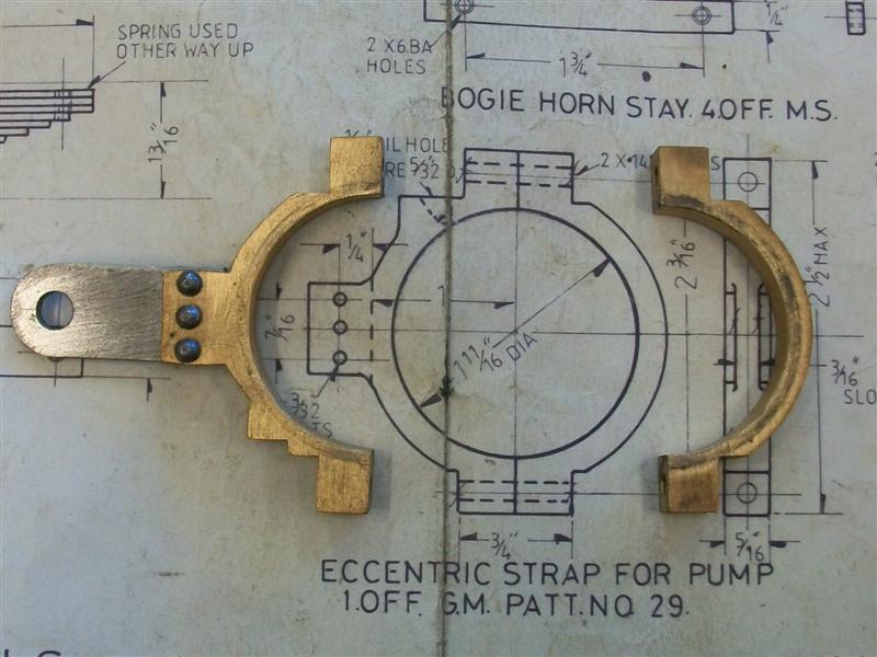 The last two jobs were to rivet the arm to the strap and drill the oil hole prior to giving the parts a polish to get them running smoothly.  Thanks for looking in Steve |
|
|
|
Post by Jim on Jun 27, 2015 22:20:28 GMT
Great work there Steve as always, well done.
I don't know if you have done it but one thing I've found handy when making eccentrics is to lightly score the diameter across the face of the bar with the lathe tool while it is still in the three jaw then rotate 90 degrees and repeat to give you a nice set of references for setting up in the four jaw to determine and bore the offset. If the eccentrics are for valves you also have the exact TDC/BDC of the eccentric making setting up the valves much easier.
I can't remember now who told me about this but it has certainly proved handy over the years.
Jim
|
|
|
|
Post by springcrocus on Jun 27, 2015 23:06:33 GMT
Great work there Steve as always, well done. I don't know if you have done it but one thing I've found handy when making eccentrics for is to lightly score the diameter across the face of the bar with the lathe tool while it is still in the three jaw then rotate 90 degrees and repeat to give you a nice set of references for setting up in the four jaw to determine and bore the offset. If the eccentrics are for valves you also have the exact TDC/BDC of the eccentric making setting up the valves much easier. I can't remember now who told me about this but it has certainly proved handy over the years. Jim I hadn't thought of that, and thanks for the tip, I shall certainly remember it. I would have used my height gauge and the work set on a vee-block but your way is much quicker. As I've always said, we never stop learning. Steve |
|
|
|
Post by springcrocus on Jul 5, 2015 6:42:23 GMT
I've had to make the main spring hangers different to drawing because I messed up on the axle boxes - I marked out the fixing holes from the wrong face and, consequently, the hanger pin would be out of position. I had no intention of scrapping the axle boxes after that amount of work so modified the spring hangers to suit. Rather than a circular base as per drawing I've made this part from a rectangle of 10swg mild steel plate and marked out the holes to suit. 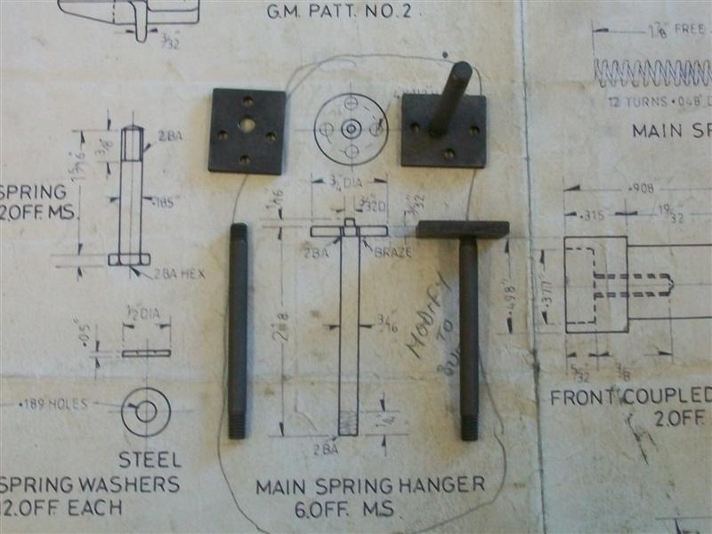 ] The rod part is 3/16" dia mild steel with a 2BA thread on each end but without the titty as there is no location point for it on the axle box. I will silver solder the two parts together a bit later on, I just need to find a way to hold the whole thing square while soldering.  Thanks for looking in Steve |
|
|
|
Post by Roger on Jul 5, 2015 8:23:38 GMT
These sort of slip ups used to really annoy me, but much of the time you can work round it like you have. I remind myself that often these things are pretty arbitrary as to how it's done it doesn't matter a jot. Sometimes you have to start from where you are, not where you'd like to be!
You're really cracking on with it, I wish I could find more time to get on with mine more quickly.
|
|
|
|
Post by springcrocus on Jul 12, 2015 18:33:56 GMT
This one is for Adam because he showed an interest in an earlier post  and also a special mention to Reg (RGR60130) and his brother John who very kindly sold me these surplus castings at substantially below list price. Many thanks, Guys. The driving and coupled wheels have the balance weights cast in and, consequently, are quite heavy but also out of balance at this stage. This meant that the lathe rocked quite a bit at higher rotational speeds. Since most of the turning was done at low speed, I decided that it wouldn't be worth trying to balance them with some bolt-on weights. First operation was to hold the flange diameter in the four-jaw independent chuck and try and get the best visual balance for the spokes and rim. The front was then faced and the tyre diameter turned about fifty thou oversize and a decent chamfer filed on the outer edge.  All subsequent operations were done in the three-jaw self-centre-ing chuck using home-made soft jaws because the chuck is a 5" diameter and the wheels are 6.9/16" at the major diameter. This method was chosen because it's quicker to load and get machining each op - soft jaws give good repeatability - and I don't have a large faceplate and didn't fancy spending all year clocking the wheels up at each operation. The jaw extensions are just bolted on with M5 cap screws but they will be perfectly OK for this application. 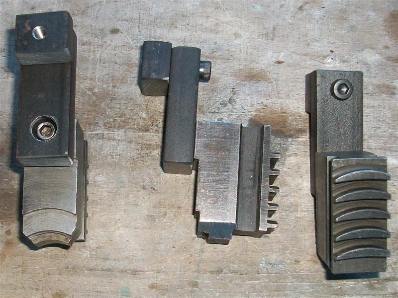  Once the jaws had been bored to suit the back was faced as a single operation, then the flange diameter turned and the axle hole drilled and bored to about fifty thou shy of finished size, all as separate operations. A ten thou depth of cut was used for all of the facing operations and each pass took about five minutes. Luckily, I have automatic feed in both axes so was able to use the waiting time to fettle out the flashing between the spokes with files and rotary burrs. 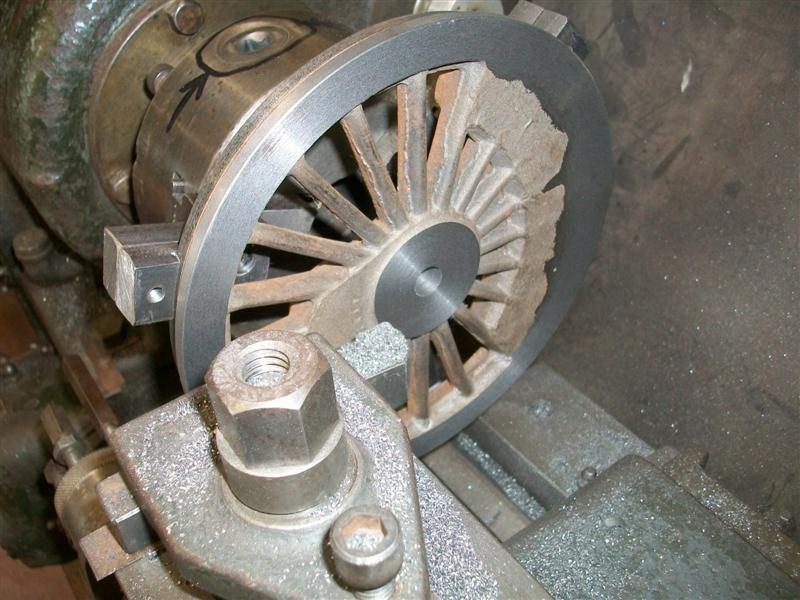 I didn't count the number of separate operations but it must have been a dozen or so.  The last two operations were to final bore the axle hole and to turn the two degree taper on the tyre section. I don't have a 9/16" reamer so I used a spare axle and polished one of the journals down a thou to give me a Go/NoGo gauge. Before doing these final cuts, I reskimmed the jaws and reduced the depth of the jaws to 70 thou so that I could form the angle on the face of the flange.  I did the bore first and, just to be on the safe side, before I turned the two degree angle on the tyre section, I clocked the bore and checked that the runout wasn't excessive. It never went worse than half a thou. 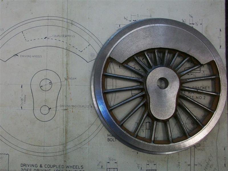 The biggest advantage of using the soft jaws and doing one operation at a time is that one can set the tool position on the first component and then not need to move the slide to repeat the operation on the remaining components. Although I only have a digital caliper to measure the tyre diameter, I can find no difference in size between any of the wheels. Now that the turning is finished, I will make a jig to locate the holes for the pivots. I also intend to key my wheels to the axles so need to sort out a way of getting that done accurately. Thanks for looking in Steve |
|
|
|
Post by ejparrott on Jul 13, 2015 8:39:01 GMT
If you bore the crankpin holes first, then make up a couple of dummy pegs, it's easy.
Peg in the crankpin hole, mill a slot across the top a very good size - anything will do, you need a length a bright bar to go across to the main bore.
Keyway broach guide bush in the axle hole, has the slot for the broach but also a matching slot across the top for the same bright bar that goes through the crankpin hole. The head of this bush is larger than standard.
Insert both pegs, use bright bar to line up with each other, clamp head of broach bush through spokes, remove straight edge, broach!
|
|
|
|
Post by springcrocus on Jul 13, 2015 19:05:46 GMT
Nice one, Ed, looks like a plan. It was reading your posts in a thread about wheel quartering that convinced me that keys were the way to go. I don't intend to start the loctite discussion again, the decision is made!
Steve
|
|
|
|
Post by springcrocus on Jul 26, 2015 17:37:33 GMT
Just a quick update to the main axles. Since I took the decision to locate the wheels using keys, I needed to mill the quartering keyways in the axles. The easy way would be to mount the axles in a rotary table or dividing head on a milling machine. However, I have neither but I do have a lump of 1" square bright mild steel bar and a length of this was used to make in indexing fixture, faced off in the lathe and a 3/4" hole drilled through it.  Britannia has a right-hand lead so the fixture was marked accordingly - as Don Ashton pointed out, it helps if they are all going the same way! - and each axle loaded in turn to the fixture which was then held in the milling vice and the first keyway cut with a 1/8" slot drill. The fixture was then removed from the vice, up and over-ed and set back into the vice for the second keyway. 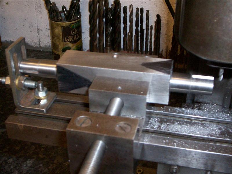 Once the wheels and crank pins are finished, it will be time to assemble the wheelsets. Thanks for looking in, Steve |
|
|
|
Post by ejparrott on Jul 27, 2015 8:26:20 GMT
Good job  I like to see people fitting their wheels and axles properly. |
|