|
|
Post by springcrocus on Apr 27, 2015 15:30:50 GMT
Thanks, Ed. I bet I still mess it up next time, though.  Steve |
|
|
|
Post by runner42 on Apr 27, 2015 22:52:02 GMT
Thanks for that Steve, well described with good photos. I didn't realise that Zeus pocketbook contains the formulae for a PCD for a specified number of holes. A PDF version of this pocketbook was available on a previous thread, I must re-acquaint myself with its contents.
Brian |
|
|
|
Post by springcrocus on Apr 30, 2015 16:54:28 GMT
The brake cylinder bracket is made from three pieces of 16 swg mild steel shaped and riveted together with a couple of bushes to carry the pivot pin. When cutting out shapes that need to be bent, I like to draw the whole thing out as a development first just so I can cut each part reasonably to size and to help decide when and where to drill any holes. Unfortunately I only have photos of the finished article so I hope my description is up to scratch. I cut out the main part first and decided to drill all the holes on the top of the bracket before bending but not the side holes in the tabs. These will be spotted through from the frames. 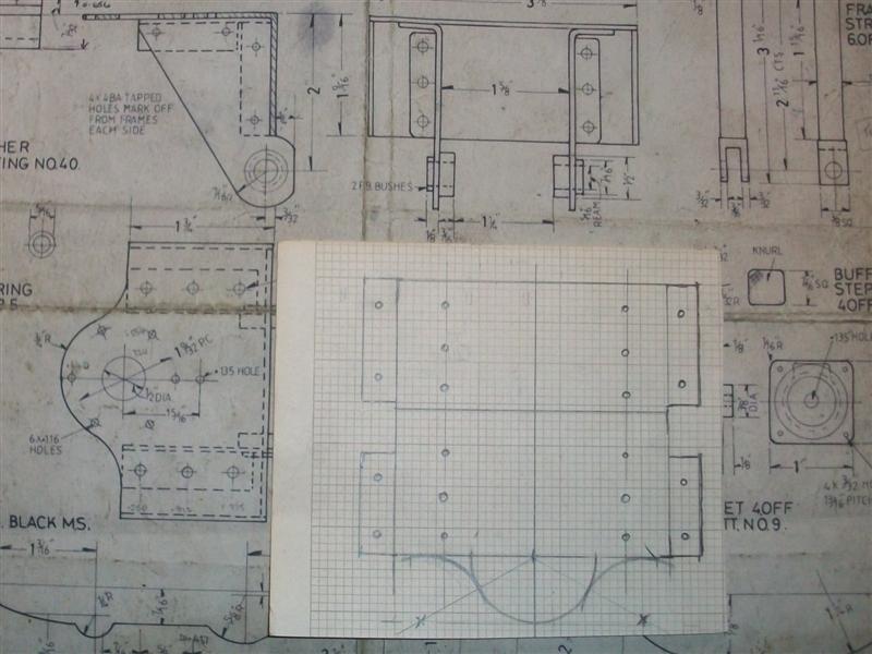 Once all the drilling was done, I then positioned the tabs by bending the two tabs on one side of the bracket in the bench vice. To get the other side bent leaving the correct width, I made a former out of a bit of flat aluminium bar that I had kicking around, milling it to about 3.260" wide. The gap between my frames is 3.395", and I subtracted two lots of 0.064" for the thickness of the sheet steel plus a few thou for luck! I was then able to use the same former to put the right-angled bend between top and back.  Next I marked out and cut out the two side pieces, drilled the holes for the pivot bushes, a fraction undersized, and then bent the tabs to a right-angle. Then it was a case of getting the sides fixed to the main part by spotting through and riveting the bits together. To get the sides spaced correctly, I planed up a piece of timber since I didn't have any suitable metal and clamped it between the side panels and then to the main bracket. It doesn't need to be particularly accurate as the other bits can be tweaked to suit. 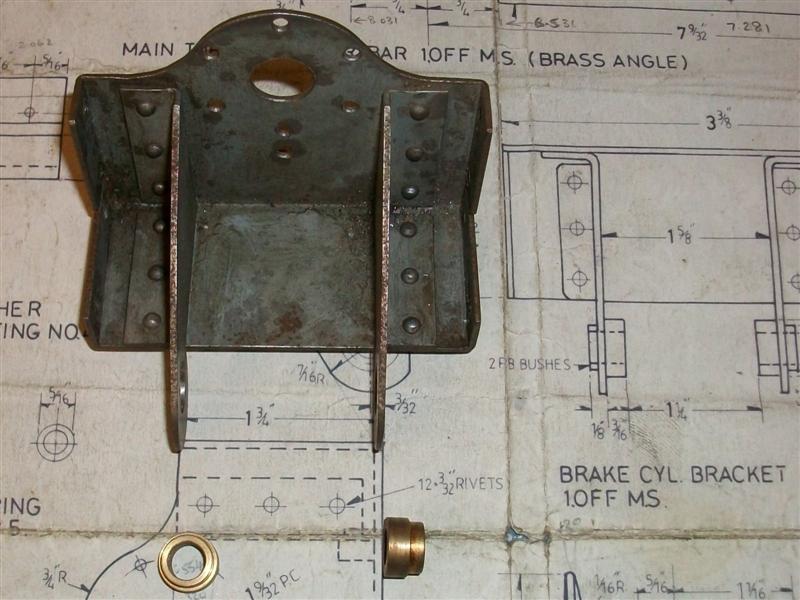 After I had riveted the assembly together, I roughly marked out a couple of the side holes with a felt tip, offered the assembly between the frames and located these holes to the corresponding holes in the frames. Then I clamped across the frames to hold the brake cylinder bracket firm and spotted through all eight holes. The bracket was then removed from the frames, drilled and tapped 4BA and should have been ready for assembly. However, I managed to strip one of the threads in the bracket - it's only 64 thou thick - so I have drilled this out to clearance size and will use a nut and bolt instead.   The drawing suggests that the two bushes are made of phosphor bronze but brass is perfectly adequate here. The duty cycle on the bushes is practically zero and the boiler will expire before the bushes wear out. The pin and bell crank will be made later when I make the brake cylinder and the bushes will be reamed to size at the same time. Thanks for looking in. Steve |
|
|
|
Post by springcrocus on May 3, 2015 12:39:39 GMT
I made the pump nut, in one visit, from 1.1/4" diameter brass held in the 3-jaw chuck of the Colchester Triumph and, once again, had the benefit of high-speed screwcutting. First, I drilled at 9/16" diameter to about 1" depth and then bored it out to 0.635" to clear the plunger diameter of 0.629" (16mm). Next I bored it out to 23mm (the core size of the thread) and finally created a 24mm diameter undercut, 3/16" long, at the bottom for the thread to run into. Using a boring bar with a triangular tip meant I could do this all with the same tool. The "O" ring will sit in this undercut. Then I screwcut the thread using a 1mm pitch insert and using the pump body as a gauge. Finally, the O/D was given a light skim to clean up and the nut parted off. I haven't put the 6BA tapped holes in yet, they're only for locking the nut to the body.  The plunger is just a bit of 16mm stainless steel with some simple machining applied to it.  Here is a picture of the pump assembled on its stretcher and fitted between the frames.  The pump strap and eccentric will be made after I have made the main axles. If I was making this assembly with the machines I have today, I think I would make an M24 (or imperial equivalent, say 40 tpi) tap out of a bit of silver steel and make the nut first, tapping the thread. Then I would make the body to suit the nut. This is because screwcutting up to a shoulder in a blind hole can be a bit daunting. Thanks for looking in. Steve |
|
|
|
Post by Deleted on May 5, 2015 19:37:18 GMT
That looks great Steve...very nice work sir.....
Pete
|
|
|
|
Post by fostergp6nhp on May 6, 2015 18:47:30 GMT
If I was making this assembly with the machines I have today, I think I would make an M24 (or imperial equivalent, say 40 tpi) tap out of a bit of silver steel and make the nut first, tapping the thread. Then I would make the body to suit the nut. This is because screwcutting up to a shoulder in a blind hole can be a bit daunting. Thanks for looking in. Steve Use a cack handed tool pointing towards the rear and screwcut in reverse so the tool traverses out of the bore. |
|
|
|
Post by springcrocus on May 9, 2015 12:20:18 GMT
The drawing indicates that the steam brake cylinder is made from a bit of brass tube brazed onto a machined boss but i've made mine from solid using 1.1/2" diameter brass. Because of this, it won't matter what size I make the bore (within reason) as long as I machine the "O" ring groove to suit.I decided to turn the back end first, facing and turning the 1/2" spigot, drilling and tapping the steam entry port and skimming the O/D. I then loaded it to soft jaws to machine the opposite end. I went this way because the wall thickness of the cylinder is a bit thin and I didn't want to risk distorting it with any form of chuck pressure. First, the billet was faced to length, then drilled and bored to my chosen size of 0.994" and finally the O/D was turned to size. Then it was removed from the chuck, offered up to the brake cylinder bracket and the six bolt holes spotted through. These were then drilled on the drill press and tapped 6BA by hand.  The piston was made from 1" diameter brass skimmed to be a sliding fit in the bore of the cylinder with an "O" ring groove cut into the O/D to provide the seal, finishing this diameter at 0.724". The locating hole for the operating pin was made by drilling with a No.4 centre drill and plunging with a small high speed steel form tool made to suit which I have since lost, so can't show it here unfortunately. Finally, it was deburred and parted off. 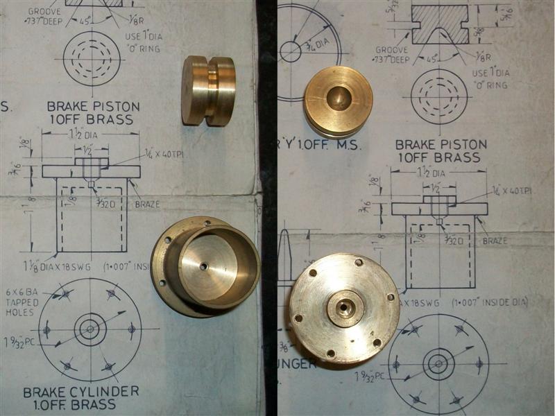 Thanks for looking in. Steve |
|
|
|
Post by springcrocus on May 10, 2015 8:06:11 GMT
The few remaining items to complete the brake cylinder assembly are the pivot pin, the bell crank, operating pin, a couple of clevis pins and the return rod with spring. With regards to this set of drawings, anything which is specified as 1/8" dia with a 5BA thread is replaced by 3mm material with an M3 thread.  The pivot pin is just a piece of unhardened 5/16" diameter silver steel, The operating pin was machined from a bit of 3/8" square mild steel, holding in my self-centring 4-jaw chuck to turn the 1/4" diameter and just filing the shape on the end. The fork was made the same way as I make all my forks, held vertically on the mill and machined through with the appropriate slot drill. The bell crank was made as two pieces and brazed together. This is a picture of the whole assembly ...  ... and here it is mounted between the frames. I have drilled and tapped a cross-hole in the bell crank to take an M3 cap screw and by locking the bell crank to the shaft I don't need to silver solder the bushes into the framework, just a dab of Loctite, so if they wear out (unlikely) I can just make a new pair and drop them in.  The brake gear will be made a bit later on. Edit: Following a note from a fellow member, I should add that quite a lot of the parts shown are a nice shiny black. At the time I made them, we were regularly sending components for treatment of one sort or another so I took advantage and had most of my mild steel parts either chemi-blacked (the shiny finish) or phosphated ( the dull black finish). Both of these finishes can be directly painted on but the chemi-blacking is better done with a primer first, to give the surface a better key. Thanks for looking in. Steve |
|
|
|
Post by springcrocus on May 16, 2015 18:22:41 GMT
I needed to think about milling the internal bearing surfaces of the main horns and I considered it easier to make the axle boxes to fit the horns rather than making the horns fit the axle boxes. In an ideal world, I would plonk the mainframe assembly, complete with horns bolted on, onto the bed of a Bridgeport, true it all up, load up a long-series 1" dia end mill and finish machine the whole thing in one visit. Indeed, this is exactly how I did it fifteen years ago. However, I set myself the challenge of machining the other set with the kit I have today. Milling on my lathe is almost a non-starter since my cross-slide has no facility for mounting a vertical slide (or any other accessory) and I don't have one, anyway. However, using my little Cowells mill for something of this size is stretching the envelope somewhat. I decided to try and use the precision milling vice to grip the horns on the frame locating flanges but first I had to find a novel way just to hold the vice because I ran out of y-axis travel if I mounted it the usual way.  Once I had worked out the best direction to work in, I then loaded the first horn casting to the vice. They are all a good fit to the frames and I would have no trouble with repeatability although to help keep them square, I dropped a couple of large dia rivets through two of the mounting holes to locate against the side of the vice. However, as I tightened the vice the feel was wrong - too spongy - so I measured the gap at the bottom of the horns, released the vice and measured again. I was springing them closed by about seven or eight thou so this was no good. I was also getting a slight lift from the moving jaw which was affecting the squareness.  I decided to treat the vice as a fixture and just lightly nip the jaws up and then use clamps to hold the workpiece down. It's getting a bit busy on here now, and it's going to take quite a while to machine the six horns. I was able to clock off of the outer edges of the external flanges to find the centre line and had to be quite accurate on this because, even though they are symmetrical, three of the horns are mirror-imaged (left and right handed) but I can't reverse my fixture so any offset from the centre line will be doubled once the horns are reassembled. 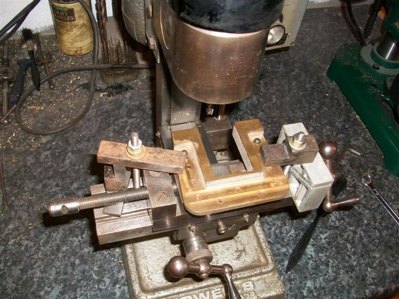 Now it was just a case of taking multiple passes up one side, across the top and down the other side until I had about twenty thou left to come out side to side. I used a 6mm carbide end mill for this as any of my smaller diameter cutters have too short a flute length and I was taking about ten thou per pass. The top didn't need so much material removed and was finished during one of the earlier passes.  Before making the final cut on each, I re-checked my centre-line position and calculated the offset either side. The finish size is 1.500", the cutter is 0.236" so the offset is 0.632" either side of centre, not forgetting to allow for backlash. And to finish the job off the corners were filed out once all machining was complete and the horns bolted back into the frames. I checked them with 1.1/2" worth of mild steel and they fit OK but they can be eased to suit with some emery on a stick once the axle assemblies are made if neccessary.  Thanks for looking in. Steve |
|
|
|
Post by springcrocus on May 31, 2015 14:05:51 GMT
The twelve spring hangers are supplied as gunmetal castings and my ones only needed a small amount of fettling prior to machining. However, because of their awkward shape they are not easy to hold for the first milling operation. Once again, I have already made these and am just re-creating the original setups, hence the holes. 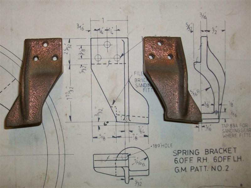 To get things started, I decided to make a mould to rest them in for the first milling operation. Some air-drying modeling clay was first placed in a matchbox then the casting, wrapped tightly in clingfilm, was pressed into it and leveled by eye. There are left-hand and right-hand parts so I then had to repeat the process for the opposite hand. These were then left to dry for a couple of days on the workshop windowsill. 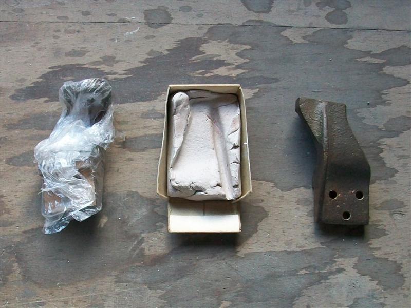 Once the moulds had gone nice and hard it was time to do a bit of machining. First, each spring bracket was loaded into the respective mould with a tiny bit of foam underneath and then the whole lot was clamped gently onto the mill table, again lining up by eye. By taking small cuts I was able to mill the frame mounting face and register, the top edge and part of the side edges. This would be enough to enable subsequent operations to be done much more easily.   Because I was able to machine the side edges, I could now hold the workpiece in a vice and machine the other side. The reason for doing this, since they bolt to the inside of the mainframes, is to make it easier to mark out and drill the holes and to provide a good seat for the bolt heads or nuts. This is an example of where a set of soft vice jaws comes in handy.  To machine the lower faces of the spring brackets I first drilled and tapped a bit of flat bar to match the bracket holes and then set this at 6 deg. on a small angle plate. I'm using a couple of angle gauge blocks but there are lots of other ways of setting the angle. It was now a simple matter to just bolt the spring brackets on and flycut the face, reversing the fixture at the half-way stage for the other hand.  The holes were spotted with a centre drill while the fixture was set on the mill and then the whole lot moved to the drilling machine and the holes drilled freehand.  Finally, some of them need a little bit of extra work to allow mounting of the sanding gear and this was done using the same fixture just bolted vertically on the faceplate. 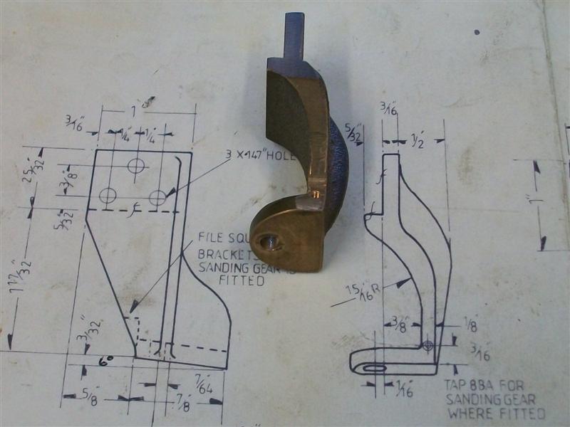 These will be bolted on a bit later, I want to make the axle boxes and axles next and finish the horns. Thanks for looking in. Steve |
|
|
|
Post by Roger on May 31, 2015 16:00:00 GMT
I love the use of the clay Steve, very cunning and not something I've seen done before. I'll remember that one, if may come in useful one day.
|
|
|
|
Post by springcrocus on Jun 1, 2015 7:18:51 GMT
My wife has, for many years, built dolls houses and accessories so there is always a pack of DAS or similar floating around. Very versatile stuff.
Steve
|
|
|
|
Post by arch1947 on Jun 1, 2015 8:49:39 GMT
Steve, The clay approach is very eligant and novel. I will keep it in mind, great work.
Regards,
Arch
|
|
|
|
Post by springcrocus on Jun 10, 2015 6:05:40 GMT
The drawing suggests using the available gunmetal castings to make to main axle boxes but I have made mine from round mild steel billets. I would have used 2.1/4" dia material but I only had 2.1/8" at the time and that's why the corners are chamfered. The back face was first cleaned up on the lathe using the 3-jaw chuck and the billet was then reversed and all other turning ops completed in one go. Depths are quite important here because the distance from axle box face to bearing depth to axle shoulder, across the axle and back up the other side to the other axle box face has to fit the distance across the horns. Bearing diameter is, obviously, also important. Because of this, after drilling the through hole I chose to do all the bores and faces at one visit using a single boring bar and using the compound slide for varying the depths. I aimed for a light press fit on the bearing bore. Once all six were done, I marked out the finish position, plus about thirty thou, of one of the sides and then hacksawed the waste off and linished them reasonably flat. This made it easier to mark out the other three sides and rough those out as well. I chose to remove most of the waste with a hacksaw to save knocking the guts out of my tiny milling machine. To finish machining the four sides, I just loaded them to the milling vice and flycut the top and bottom edges first, keeping a check on the wall thickness to make sure the bearing bore stayed central. Then the sides were done in a similar fashion although a little more care was taken here to get the size bang on.  All that was left to do was to mark out all the various holes and then drill and tap as appropriate. I wont bother with the oil holes, though, because I am using sealed-for-life bearings. Thanks for looking in. Steve |
|
|
|
Post by joanlluch on Jun 10, 2015 11:40:27 GMT
I would suggest that the LBSC design for the assembly of the axle boxes in the Britannia is a bad one. The reason is that it relies on the ball bearings to keep axles aligned to their axle boxes. For my (lsfornells) locomotive I used the same design because my early inspiration was the 5"G Brittania plans, but as said having it that way is essentially not the best approach. This works, but the correct approach would be to link each pair of axleboxes together, to prevent titling (or bending) forces being applied to the bearings, for example by means of a tube connecting the two axle boxes. This would enable ball bearings to exclusively deal with radial and axial forces, which is what they are designed for. The correct approach was already used by John (Baggo) on some of his models. See this as an example: 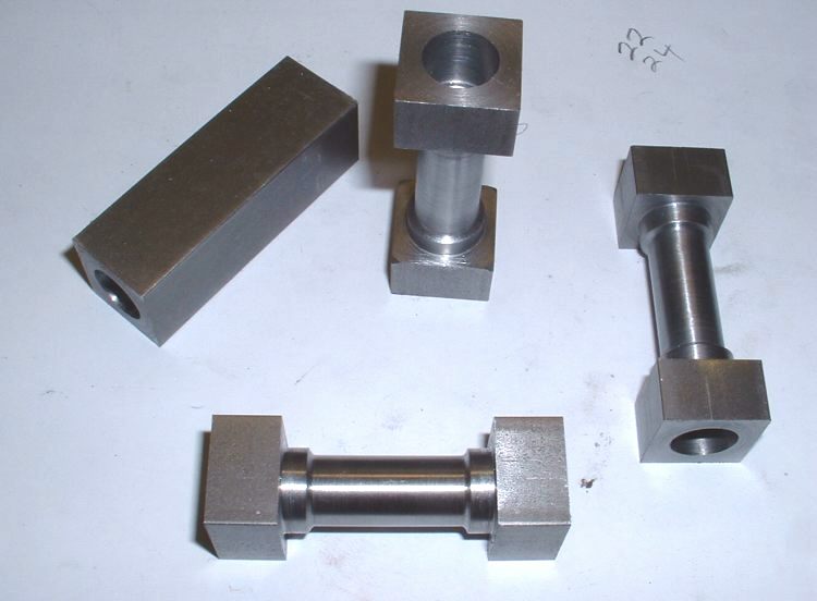 |
|
|
|
Post by Cro on Jun 10, 2015 13:18:26 GMT
I don't think the design can be that bad if you consider how many hundereds of Brits are out there. It is probably one of the most common loco with almost one in every club I would say so this design can't be far off working well. I think looking into the forces you are talking about in so much detail is over engineering something that is fairly simple.
|
|
|
|
Post by Cro on Jun 10, 2015 13:51:17 GMT
Im not disagreeing that's how bearings work but I think you over estimate the movement an axle box has withing the horn and how it moves during typical running.
I'm just saying I think you might be looking into it in to greater depth with regards to the amount of moment the boxes have, how they go and what a beariing will take.
|
|
|
|
Post by Roger on Jun 10, 2015 14:00:09 GMT
Im not disagreeing that's how bearings work but I think you over estimate the movement an axle box has withing the horn and how it moves during typical running. I'm just saying I think you might be looking into it in to greater depth with regards to the amount of moment the boxes have, how they go and what a beariing will take. It's probably less of an issue with plain bearings, I do like the idea of them being linked if they are ball bearings though. Ball bearings aren't really designed to handle situations where the races are not axially aligned so they will get a hard time if the axleboxes are stiff in their housing. |
|
|
|
Post by springcrocus on Jun 11, 2015 6:47:21 GMT
Oh dear!! Calamity!! The whole design is flawed.  What shall I do? Bin the lot, scrap the whole project??? Sorry, but there is an awful lot of rubbish aired on this forum at times. Anyway, I'm just building it, not designing the damned thing!  Back to the build... Steve |
|
NickM
E-xcellent poster
  
Posts: 230
|
Post by NickM on Jun 11, 2015 12:29:36 GMT
Steve,
Stick to playing the piano mate, you doin' fine. To quote the late, great Les Dawson, you're playing all the right notes, just not always in the right order!
Joan, you know jack **** about bearings.
Have a nice day y'all!
NickM
|
|