|
|
Post by Deleted on Dec 24, 2017 16:02:18 GMT
I love the quality of the work on those cylinders Dazza.....top work sir..
Pete
|
|
|
|
Post by Oily Rag on Dec 25, 2017 20:33:08 GMT
|
|
|
|
Post by Oily Rag on Jan 1, 2018 20:30:05 GMT
Redesigned cross heads underway in LG2 bronze. Simple stuff in our stinking hot humid weather and the storms were a welcome relief for 30 mins.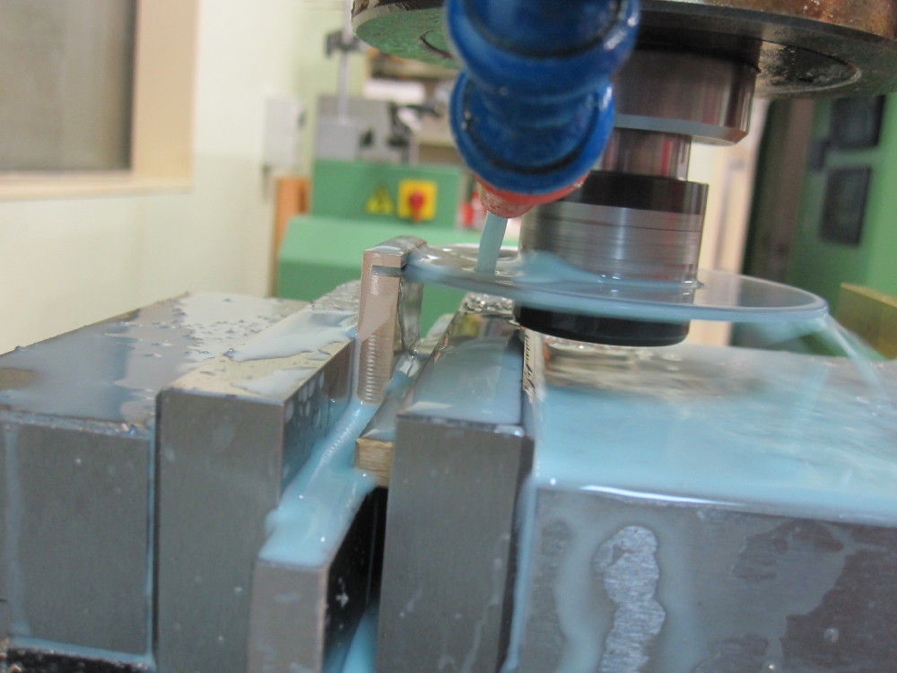 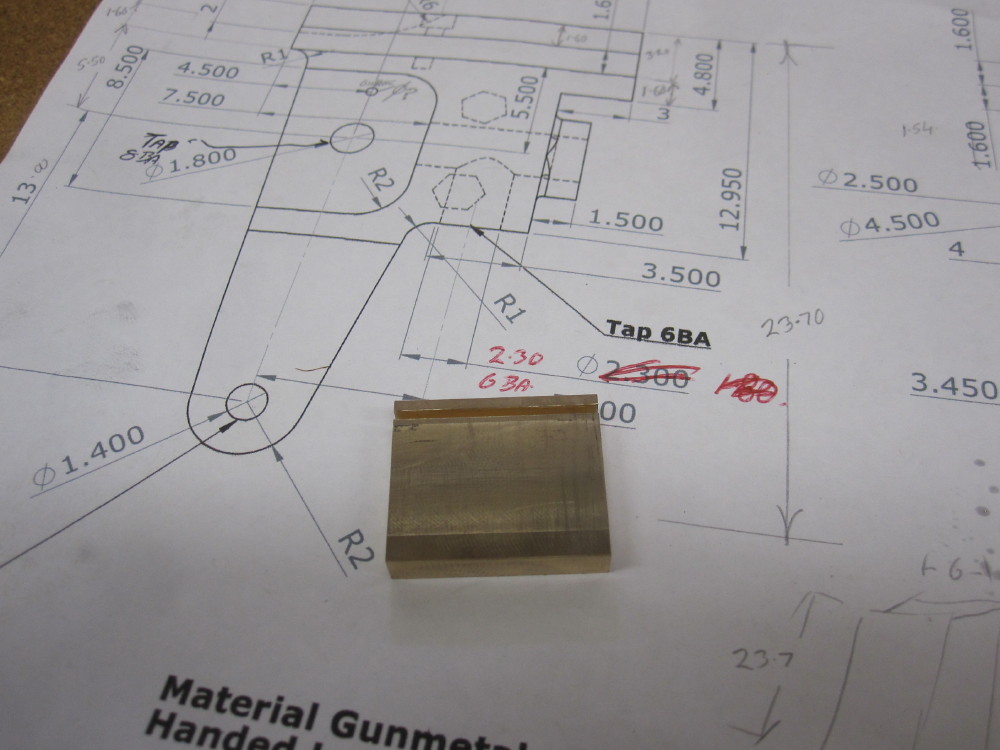 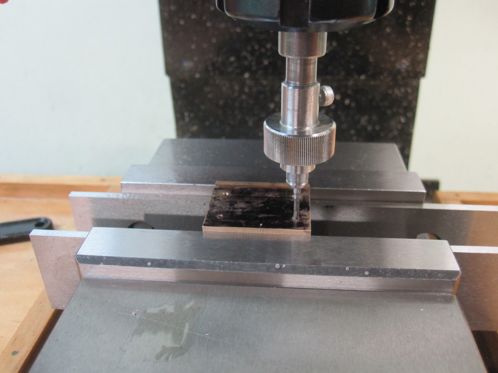 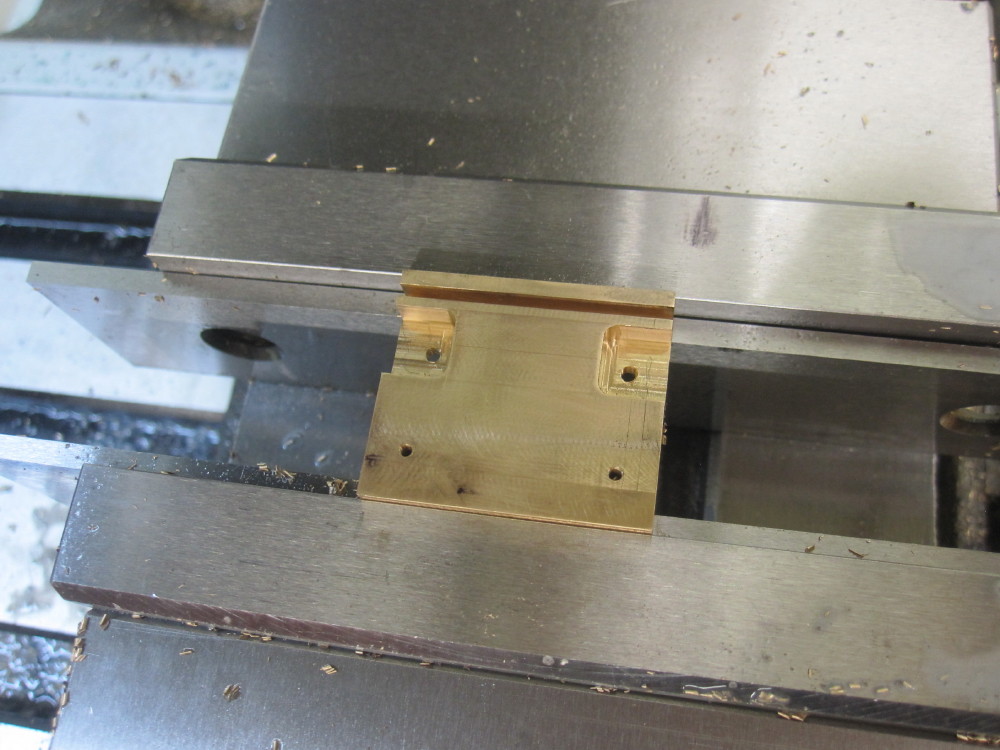
|
|
|
|
Post by Oily Rag on Jan 1, 2018 20:35:35 GMT
|
|
|
|
Post by Oily Rag on Jan 2, 2018 20:00:47 GMT
A wee bit more done last night, some passes with the mill
while the mosquito coil smouldered after the storm passed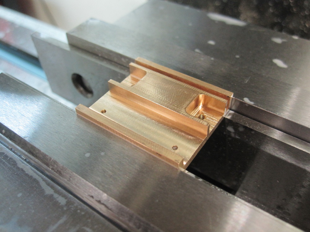 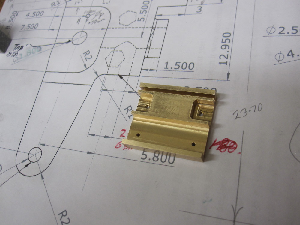
|
|
|
|
Post by Oily Rag on Jan 7, 2018 20:37:21 GMT
Done , but for breaking the edges, all was spot on and fitted nicely on the slide bar and the piston rod slid in. A lot of work for these little fellas!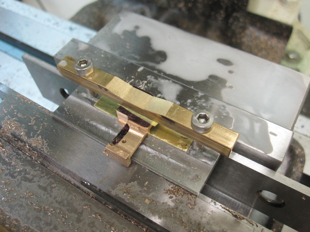 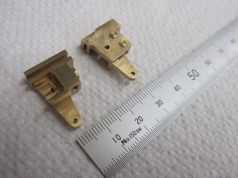 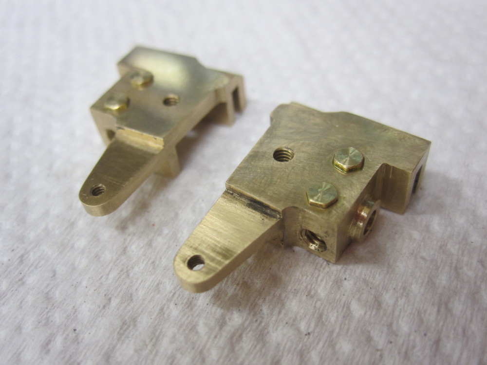
|
|
|
|
Post by Roger on Jan 7, 2018 22:12:50 GMT
"..... A lot of work for these little fellas! " ... Yeah, but so worth it, a cracking result. |
|
|
|
Post by Oily Rag on Jan 16, 2018 21:28:21 GMT
Silver steel filing buttons, hardened right out and a 10 BA screw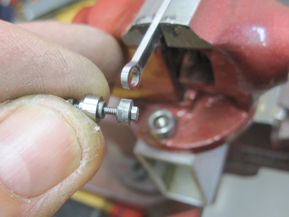 file file file, sand sand file file file, sand sand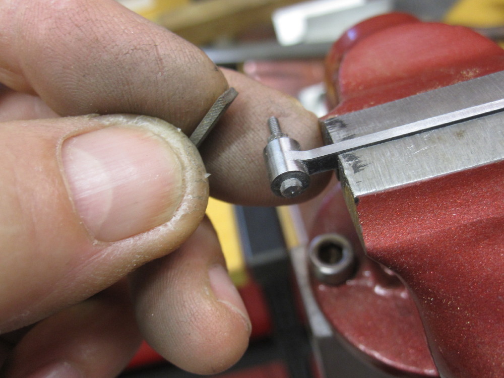 each weighs in at 4.45 grams according to Solid Works each weighs in at 4.45 grams according to Solid Works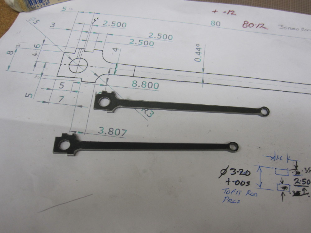 What is next here ? What is next here ?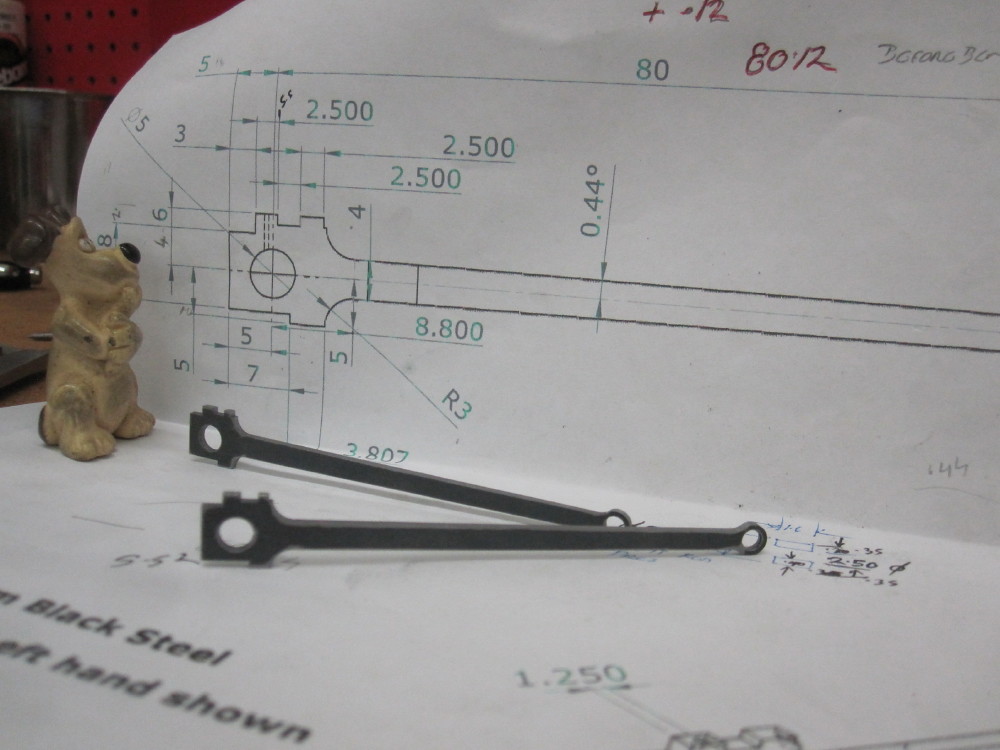
|
|
|
|
Post by Oily Rag on Jan 21, 2018 20:26:12 GMT
Fiddly work.
Slide bars in place and the cross heads are moving, attached to piston rods.
Left hand side needed .02mm removed from the bar at the cylinder end and .20mm at the MB mount.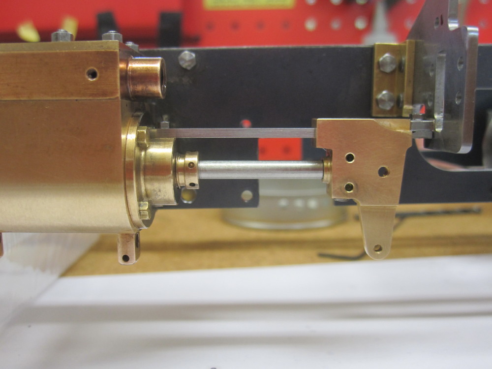 The dummy bolt heads that were loctited in fell out with the constant handling. I will clean and refit some replacements later. The dummy bolt heads that were loctited in fell out with the constant handling. I will clean and refit some replacements later. The right hand cylinder needed .20mm shim at the MB mount. The right hand cylinder needed .20mm shim at the MB mount.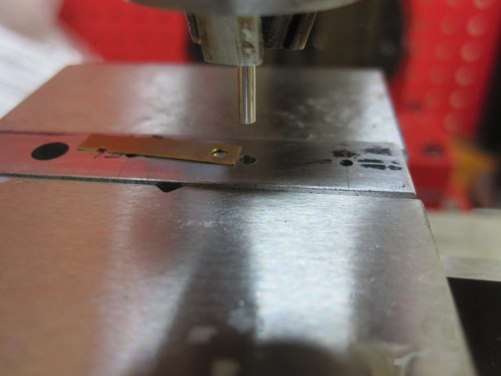 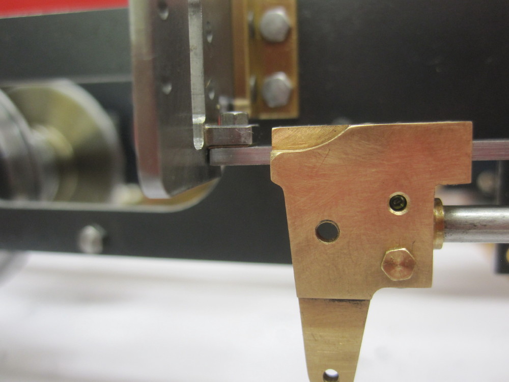 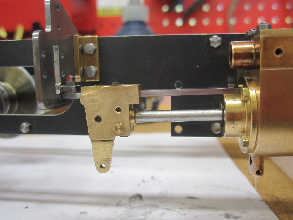
I have concerns about the drag with the quad rings that I used on the piston.
Next is the bushes and pins and complete the con rod.
|
|
|
|
Post by Roger on Jan 21, 2018 20:33:19 GMT
Great progress. With regard to the drag on the quad rings, you'll probably be able to get away with very little compression.
I imagine you can reduce the size of the inside diameter to adjust it. I'd try it first though.
|
|
|
|
Post by Oily Rag on Jan 21, 2018 21:02:54 GMT
Great progress. With regard to the drag on the quad rings, you'll probably be able to get away with very little compression. I imagine you can reduce the size of the inside diameter to adjust it. I'd try it first though. Rodger, I did just that and improved the situation, If I take more off I am afraid it may be too much. MAM has a round house kit and I like the feel of that cylinder, it uses O rings and I may dismantle it and take some measurements in case I have to remake the pistons at a later date. |
|
|
|
Post by Oily Rag on Jan 28, 2018 21:10:55 GMT
I checked the end clearances in the cylinders and it was close, but to fiddle it and to snug up the piston rod so it was up against the crosshead so any possibility of slippage (grub screw grip )in one direction is removed I made up some thin washers with 2.5mm ID and 4.5mm OD. Made the punch and then clamped them up and turned the OD to 4.5mm. 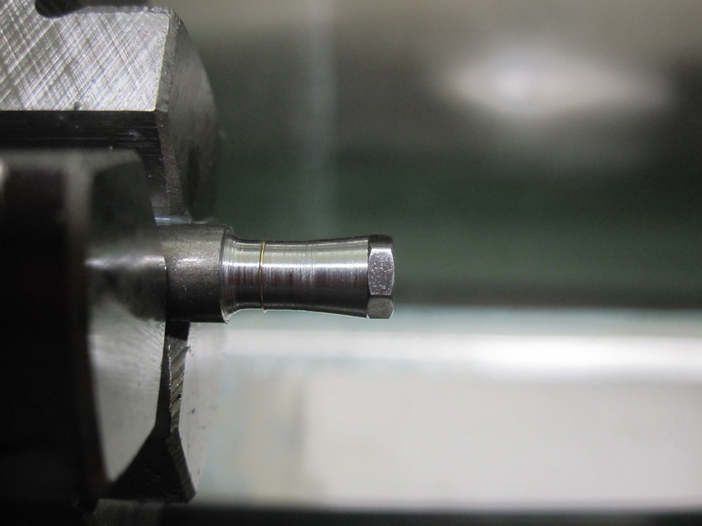 Then fitted the little fellas and the piston end clearances was within .03mm of design intent. If one is measuring and making to tolerances then there will be a small amount of lost motion in the valve gear and motion as unlike CAD which is absolute there is some lost movement in the actual loco as there is all the small amounts of bearing clearances taken up when all is moving, so the end result at the valve and piston is a bit less then design. Just like full size, as the wear takes place this lost motion increases. Then fitted the little fellas and the piston end clearances was within .03mm of design intent. If one is measuring and making to tolerances then there will be a small amount of lost motion in the valve gear and motion as unlike CAD which is absolute there is some lost movement in the actual loco as there is all the small amounts of bearing clearances taken up when all is moving, so the end result at the valve and piston is a bit less then design. Just like full size, as the wear takes place this lost motion increases. 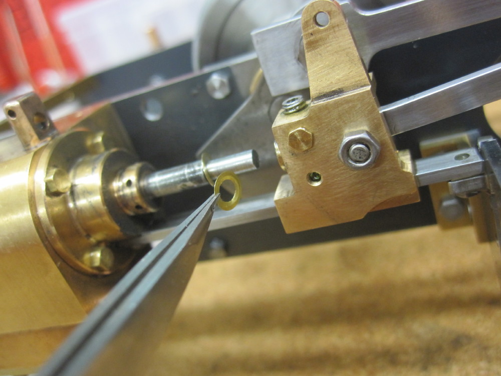 All goes around as nice as expected. All goes around as nice as expected. 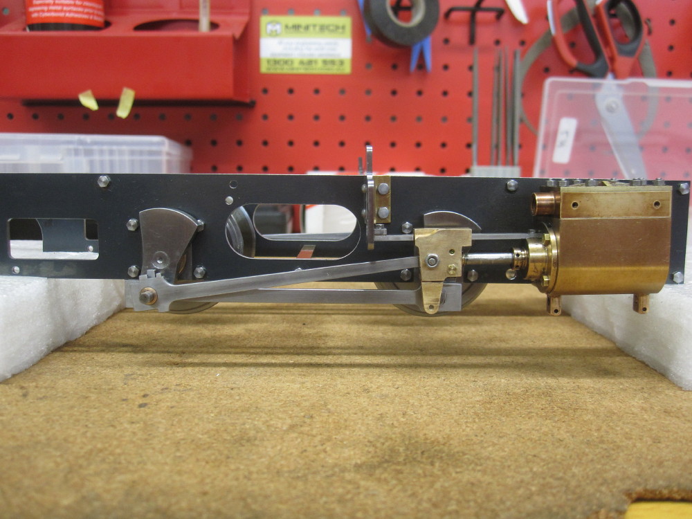 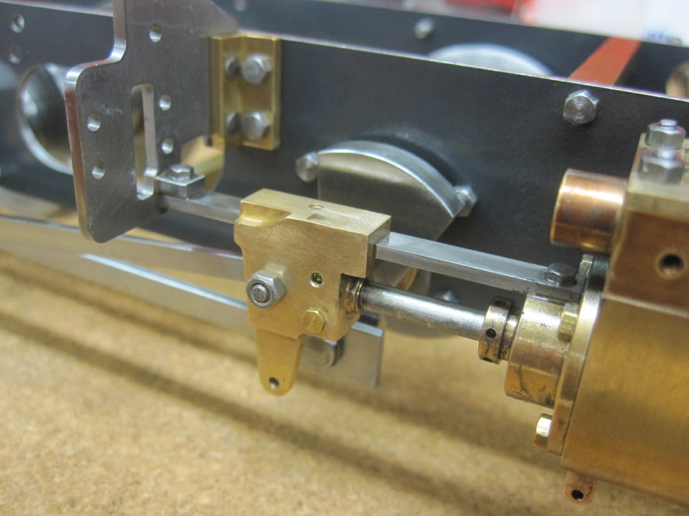 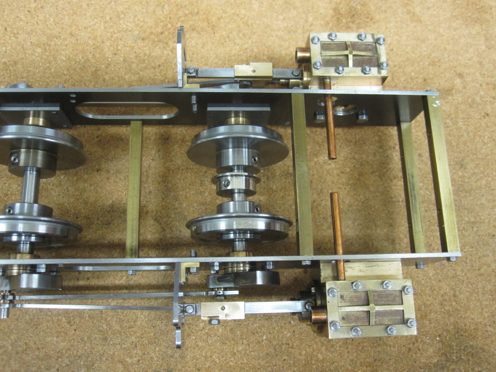
Annealing what will be the combination levers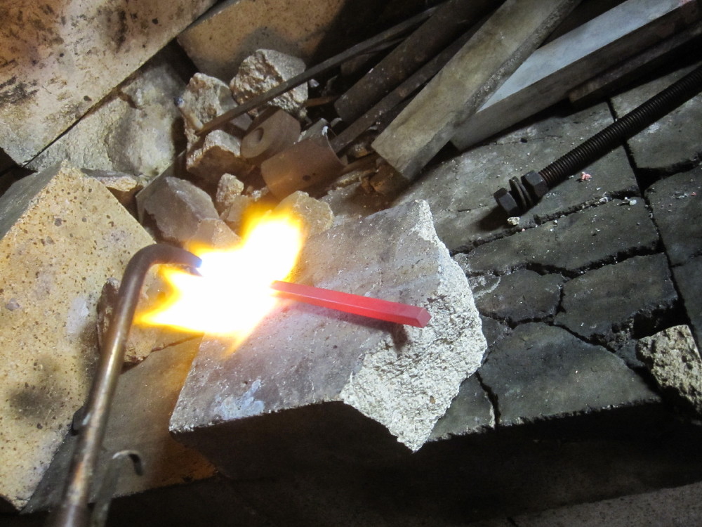 A chap at the 16mm mob asked me where are the corks A chap at the 16mm mob asked me where are the corks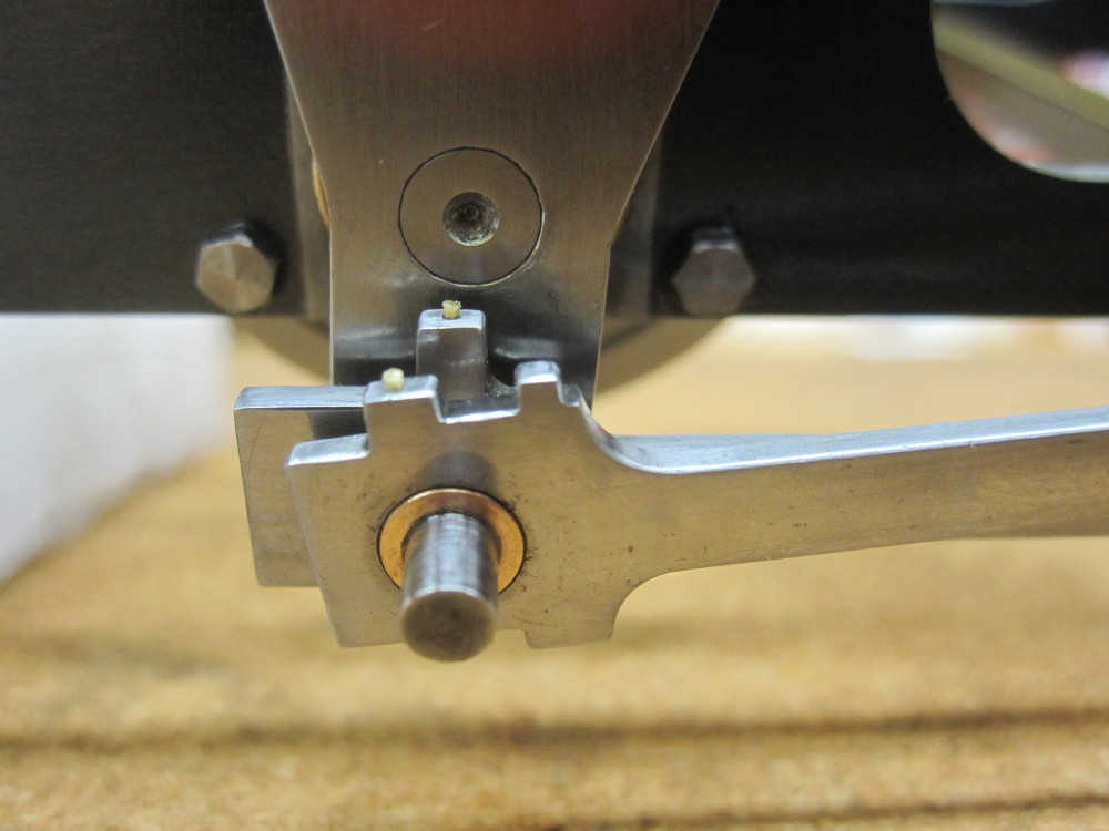
|
|
|
|
Post by spudy on Jan 30, 2018 21:39:17 GMT
You are making a lovely job of this little Loco. I look forward to seeing more work on it.
|
|
|
|
Post by chris vine on Jan 31, 2018 16:06:59 GMT
Hi Darrell,
I love the progress and quality of your work on the loco.
One thought for you: You mention lost motion and how it will reduce the travel of the piston. I think that in fact it will increase the travel.
If you are driving the piston slowly with the crank, (as in turning the engine over by hand) you are correct, you will get some lost motion due to clearances in the bearings.
But if the piston is driving the crank, then all clearances will allow the piston to travel further...
It won't matter as you have sorted it all out very carefully with shims.
Chris.
|
|
|
|
Post by Oily Rag on Jan 31, 2018 20:34:39 GMT
You are making a lovely job of this little Loco. I look forward to seeing more work on it.
Thank you, after decades of being an armchair modeller I have to get cracking before I am pushing up the daisies. |
|
|
|
Post by Oily Rag on Jan 31, 2018 20:44:01 GMT
Hi Darrell, I love the progress and quality of your work on the loco. One thought for you: You mention lost motion and how it will reduce the travel of the piston. I think that in fact it will increase the travel. If you are driving the piston slowly with the crank, (as in turning the engine over by hand) you are correct, you will get some lost motion due to clearances in the bearings. But if the piston is driving the crank, then all clearances will allow the piston to travel further... It won't matter as you have sorted it all out very carefully with shims. Chris.
Regards to the motion for the pistons, yes, of course you are correct, and I needed to get my head around that, even the simple things escape my slow and dim mind. I meant to say that I understand the valve events become later as the wear in the eccentric bush, die block, radius rod and valve cross head pins take up. Am I correct on that ?
There is no axle box slop in this little loco to be concerned about. :-)
In my dreams, or is it my nightmares, I would like to one day make my 5" gauge C17 #253 and take it to the UK and come back with a medal, just one significant to thing to have achieved in my life, but as the Buddha says, " A man with no wants, is a free man" so I should just enjoy what ever eventuates and be content, eh!
Also I am faltered by your kind comments and the other kind comments from others, thank you. |
|
|
|
Post by Oily Rag on Feb 4, 2018 2:37:42 GMT
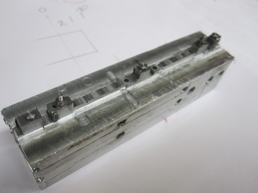
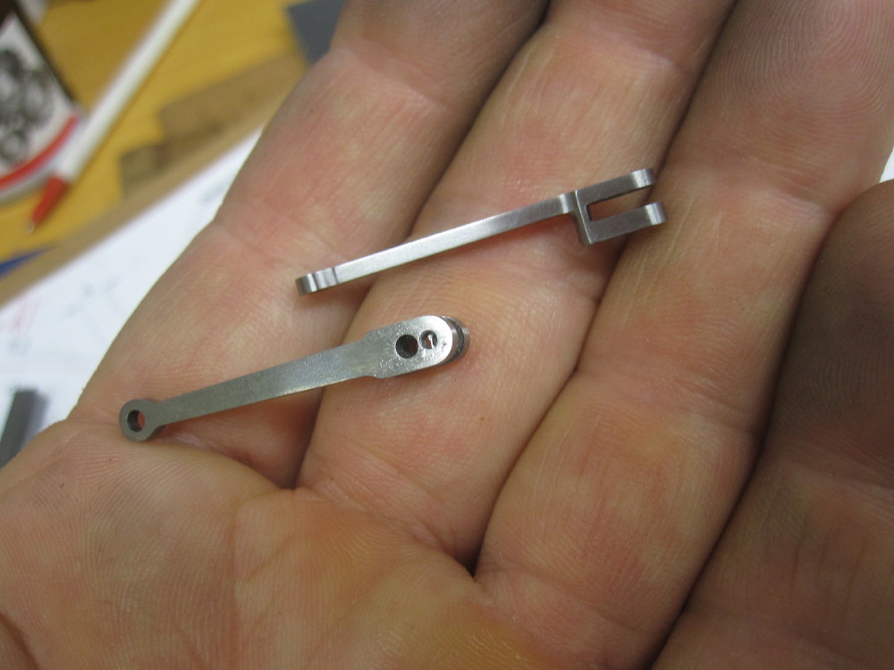
The alloy square section which has had 2 sides used for screwing the rods down when machining has a quick mill/face over one of the remaining sides to prepare it for the thinned 1/4" annealed steel piece to be screwed down on it. Drill and ream and tap threads. Two combination levers are in the one piece.
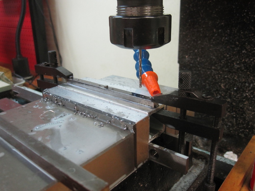
Thin out section with a cutter that has rounded corners.
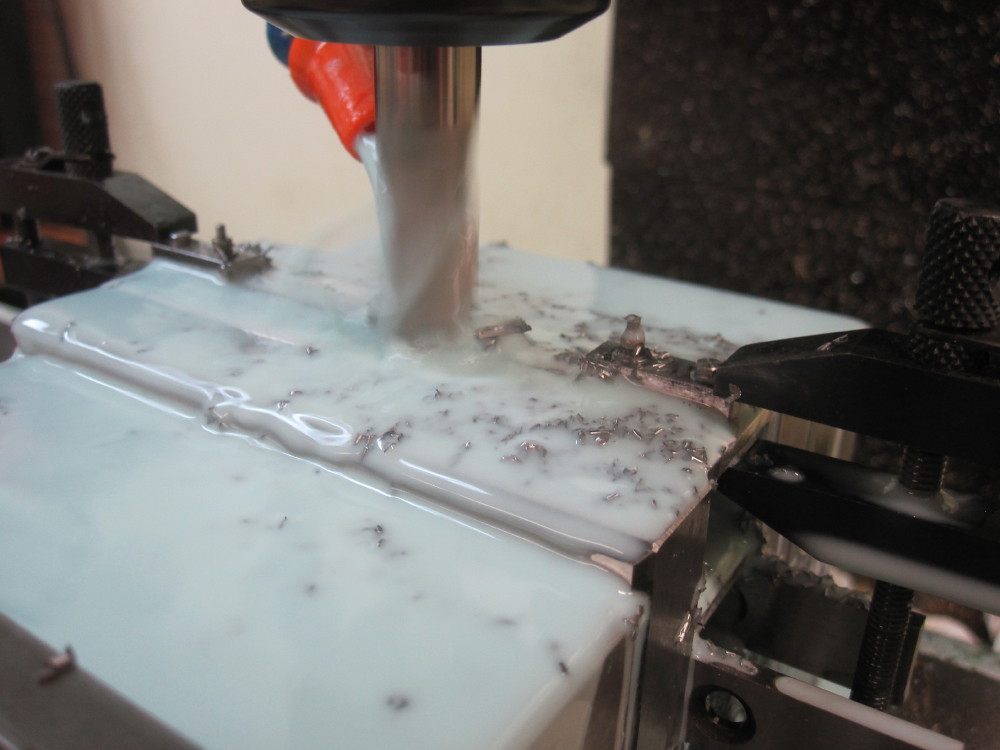
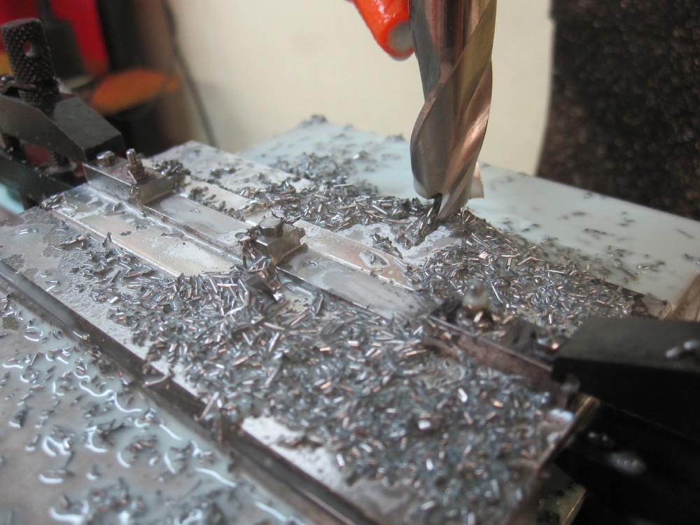
Blow clear.
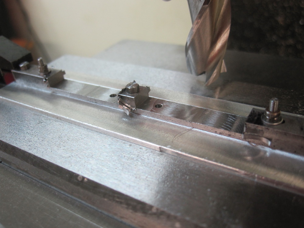
Rounded corner.
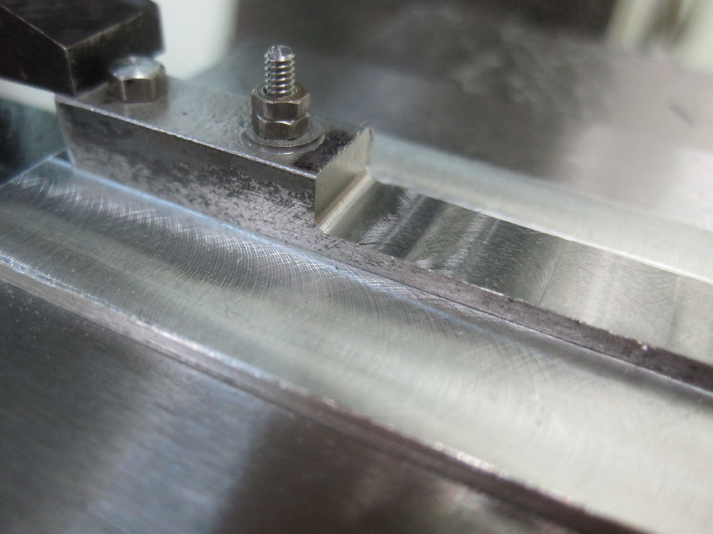
Now milling down the sides to bring it all down to 4.00mm The centre line of the holes is Y=0 so the DRO was used to work out where I am going, via notes and chook scratchings.
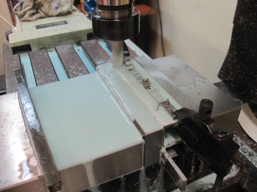
The tool makers clamps was just extra insurance for my sanity.
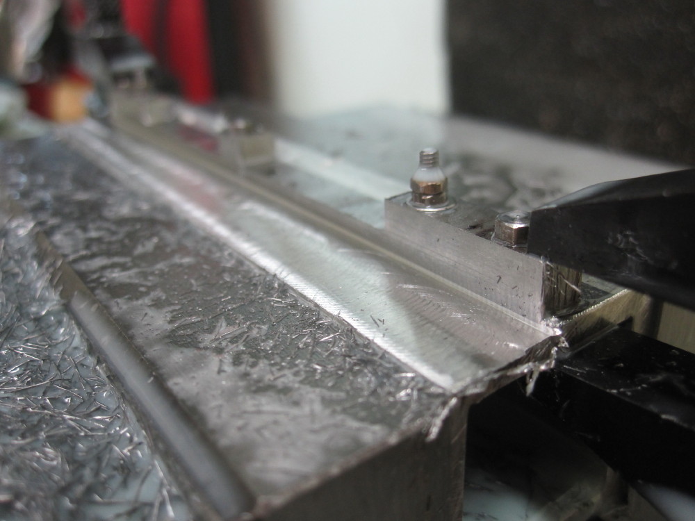
Work out a few more co-ordinates and start the outside profile. Those with CNC mills can have this easy, but for me it is "See and See" milling with DRO assistance.
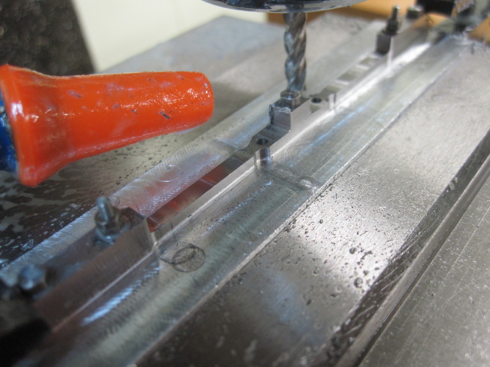
Looks like this when removed from the mill.
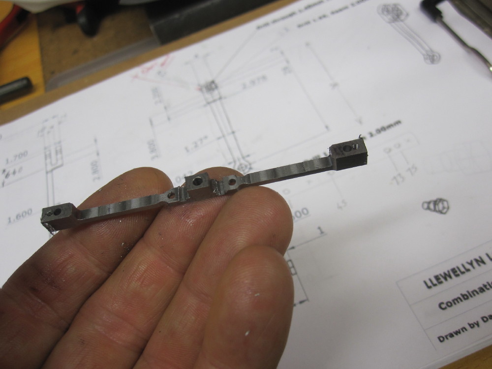
A bit more milling to get the taper, but a lesson learnt. NEVER NEVER buy cheap mill cutters. Brand new!
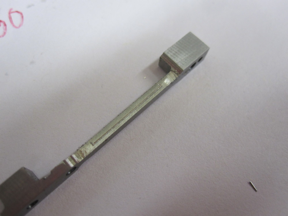
Badly made.
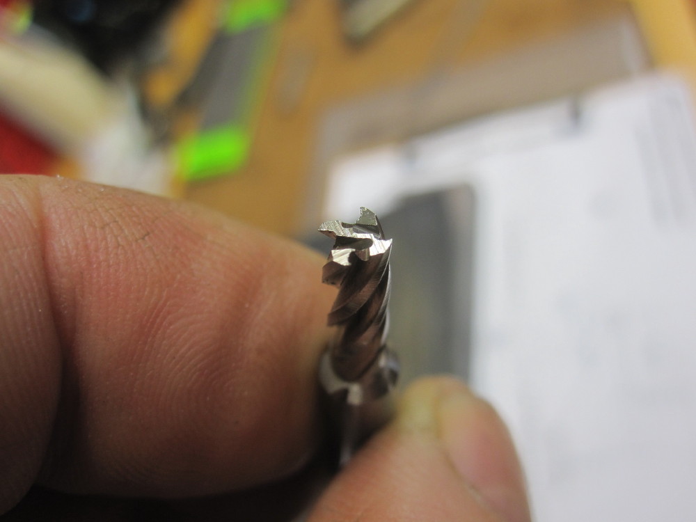
The moral is for me in OZ is "Sutton" or "Osborne" or similar breeds.
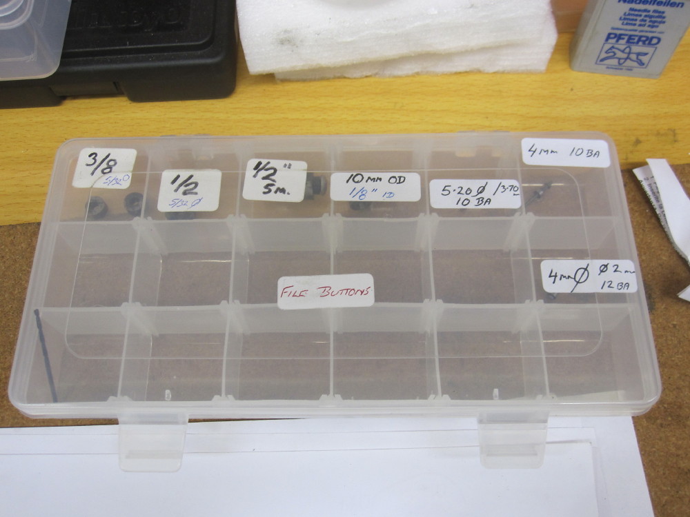
Made another set of filing buttons, 4mm OD with 2mm ID and 1.3mm hole for 12 BA screw x 2.
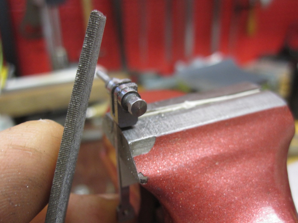
The collection is growing.
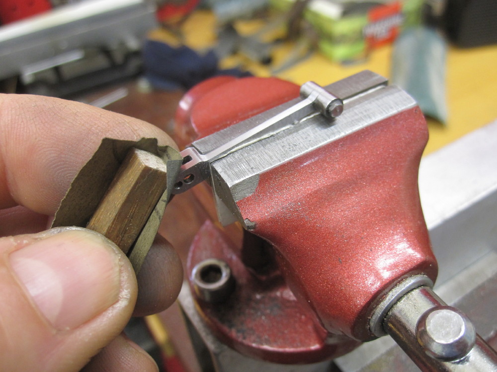
a rub a dub rub with 600 and 1500 grit.
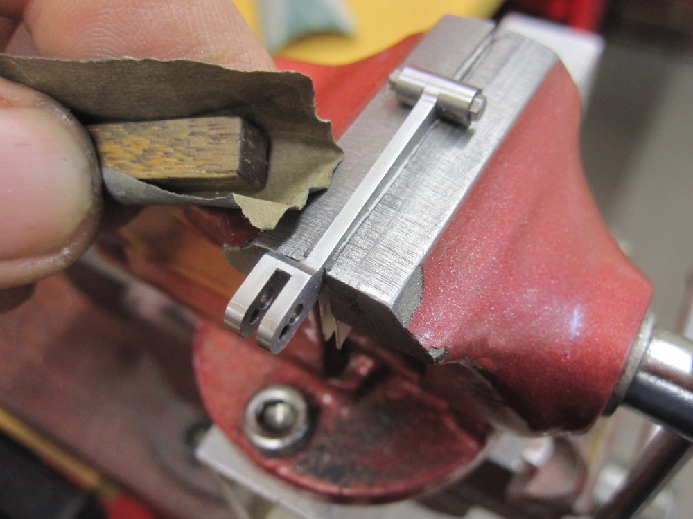
Oil them over, done, not perfect but I am pleased and satisfied.
|
|
44767
Statesman
 
Posts: 538
|
Post by 44767 on Feb 4, 2018 7:33:48 GMT
Lovely work, Darrell. The best advice is to have well made, sharp cutters, as you say.
|
|
|
|
Post by chris vine on Feb 5, 2018 9:35:01 GMT
I once travelled on a steam locomotive in The Ukraine, on the footplate at night. An exhilarating experience!
The most memorable part of it was that there was this constant banging sound (and vibration) twice per revolution. Clearly something was worn; it was as if someone was smashing the frames with a huge sledgehammer.
Next morning I watched from the side as the engine was moved slowly. There was some play in the big end bearing. About 5 mm!!
Chris.
|
|
Lisa
Statesman
 
Posts: 806 
|
Post by Lisa on Feb 5, 2018 11:15:39 GMT
One of the preserved lines near me had something similar Chris, the hole in the axlebox had worn such that it was about an inch bigger than the axle! Loco was still in service though, running monthly.
|
|