johnthepump
Part of the e-furniture
 Building 7 1/4"G Edward Thomas
Posts: 493 
|
Post by johnthepump on Nov 22, 2016 15:51:05 GMT
I know that some on this forum don't like sharpening cutters, but once retire ones views change a little. I do like carbide tipped tools and milling cutters, some times and if you have the equipment sharpening HSS tooling makes sense. Back in October 2013, I set up to grind a long series end mill specifically to do the finishing cuts to the horns after they have been fitted into the frames this is about to happen, so times in this hobby the road is long and the distractions plenty. I did take a photo back then although the cutter is shorter and was the test run, the two others followed and they have all been put away until now. I will post photo's of them in action when I do the horns. John. 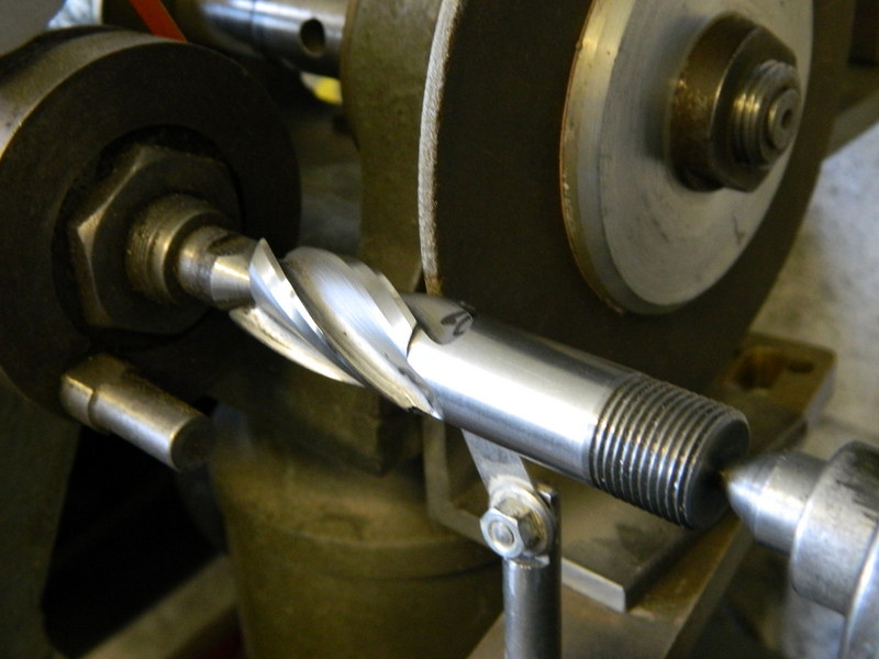 cutter cutter by John The Pump, on Flickr 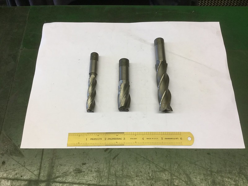 22.11.2016 22.11.2016 by John The Pump, on Flickr |
|
|
|
Post by Deleted on Nov 22, 2016 16:34:16 GMT
interesting,,,all of my cutters are blunt to one degree or another so I will be paying particular attention to this John..
cheers
Pete
|
|
johnthepump
Part of the e-furniture
Building 7 1/4"G Edward Thomas
Posts: 493
|
Post by johnthepump on Nov 29, 2016 23:32:02 GMT
With no one bringing any projects along this evening, so we got on with my frames. Firstly all the required countersinks were drilled and 8, 2 BA holes tapped. With this done we were able to make start on riveting the horns in place, the Myford was set up to trim the rivets to length and a late visitor got on with this task while two of us started setting rivets using the fly press by the end of the evening we had fitted the front horns and started on the rear ones. No doubt Wilf and myself will progress the job further. Over the weekend I cleaned up the rear buffer beam and sprayed it with primer. John. 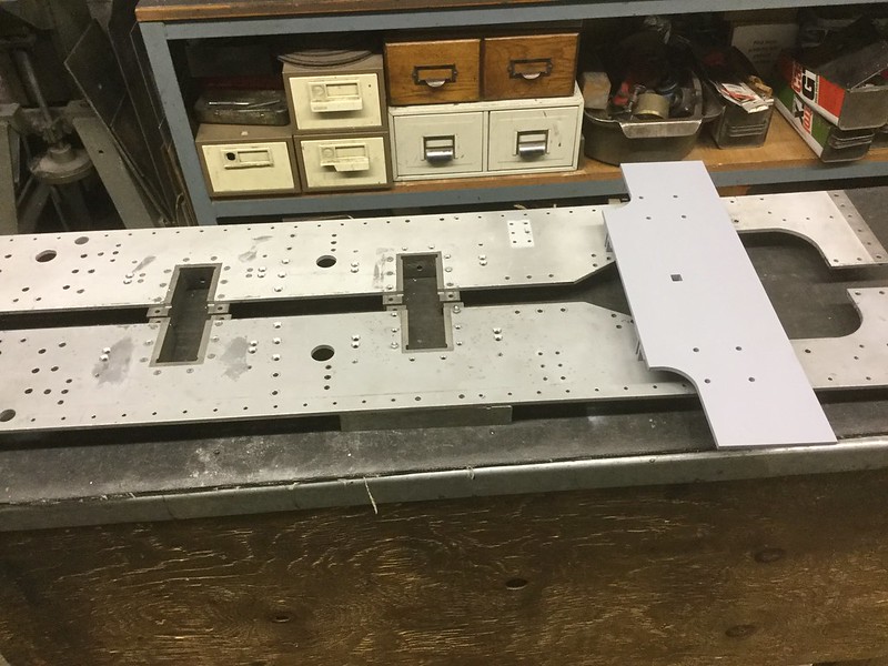 29.11.2016 29.11.2016 by John The Pump, on Flickr |
|
johnthepump
Part of the e-furniture
Building 7 1/4"G Edward Thomas
Posts: 493
|
Post by johnthepump on Dec 1, 2016 11:14:34 GMT
Wednesday evening, only Wilf turned up so we carried on with riveting in the rest of the rivets to hold the horns in place. Wilf got on the Myford and shortened the rivets to the required length while I set them using the flypress, the only deviation from this work was to look for the material needed for him to make a chuck key for a 4 jaw chuck that he had bought from EBay for his recently acquired Myford 254. With the horns riveted in it was now time to bolt the frames together and mount them up in the mill and machine the horns to their final width, I had left the gap 60 thou undersize. It was now time to use that long 3/4" end mill that I had sharpen up 3 years ago special just to do his job. 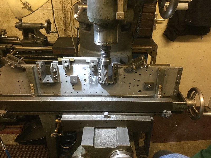 30.11.2016 30.11.2016 by John The Pump, on Flickr The rubbing down and filler that can be seen each side of the front horns is where I have riveted in and filled when the wrong dimension was used for the spring hangers we only noticed the difference when the hole each side of the rear horns. The frames were co ordinate drilled on the mill using the DRO ten years ago and the horn casting were machined and drilled this year on the same mill and DRO and they fitted together perfectly and all the rivet holes lined up. Anyone thinking of investing in a DRO for their mill I can recommend them. The cloth peg halves are used as wedges to hold the 2 steel bars up tight to the back edge of the T slots to line up the frames, I had never thought of the use for pegs it was something that Wilf suggest last evening, I hope that SWMBO doesn't find out where the are going in future. |
|
johnthepump
Part of the e-furniture
Building 7 1/4"G Edward Thomas
Posts: 493
|
Post by johnthepump on Dec 8, 2016 10:58:56 GMT
Last evening, we set about riveting the angle iron stiffeners to the frames, having finished the final milling of the horn slots to size the previous evening. The frames can now be reassembled and lots of bits bolted back on. John.  07.12.2016 07.12.2016 by John The Pump, on Flickr |
|
johnthepump
Part of the e-furniture
Building 7 1/4"G Edward Thomas
Posts: 493
|
Post by johnthepump on Dec 13, 2016 23:07:09 GMT
Over the weekend I managed to clean up the frame parts and give them a coat of grey primer, this afternoon I set about putting the chassis together along with all the other parts that had been made. The axleboxes are the job that I intend to make next, at the moment and just for display there are some plywood blocks with a half round in the underside to fit the axle. I'm am pleased with the progress that has been made on this loco this year and I have Wilf to thank for giving me the push I needed to get on with it and the help as well. John. 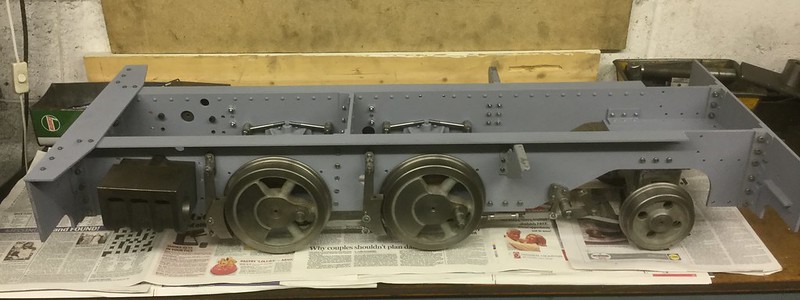 13.12.2016 13.12.2016 by John The Pump, on Flickr |
|
johnthepump
Part of the e-furniture
Building 7 1/4"G Edward Thomas
Posts: 493
|
Post by johnthepump on Dec 15, 2016 10:00:04 GMT
Wednesday evening in the Pumphouse, after putting all the made bits on the frames the previous evening and saying the next job was the axle boxes. A start on these was made, a billet of cast iron was cut into to pieces of a size for machining, while I was doing this Wilf machined the rest of the cylinder mounting bolts to length. 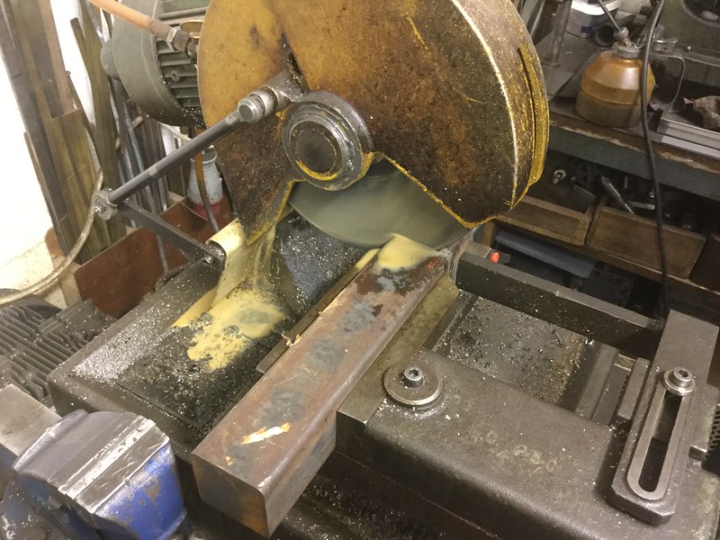 14.12.2016 14.12.2016 by John The Pump, on Flickr As the wheels sets were already made, we decided to make split axle boxes in the same way that Ken Swan's Jessy are, the loco which Wilf is building, hence the extra 4 smaller blocks in this photo. 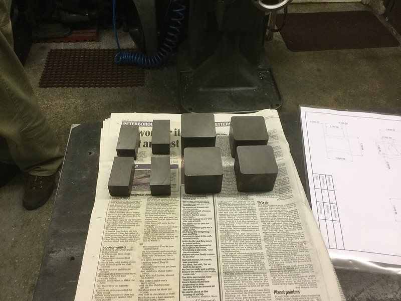 14.12.2016 14.12.2016 by John The Pump, on Flickr As all this was going on Martin turned up, we hadn't seen him for a while , it turns out he had been up on the F.R. working with a track gang laying the three roads into the new heritage carriage shed at Boston lodge. 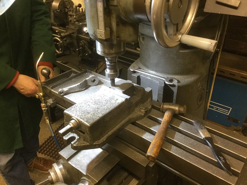 14.12.2016 14.12.2016 by John The Pump, on Flickr With the material cut up Wilf set about facing off the larger blocks on the mill using the brand new 16mm carbide insert endmill that I had bought from Greenwood tooling at the Midlands ME a month or so back, I put the 4 jaw up on the LeBlond and started facing one end of a the smaller blocks. 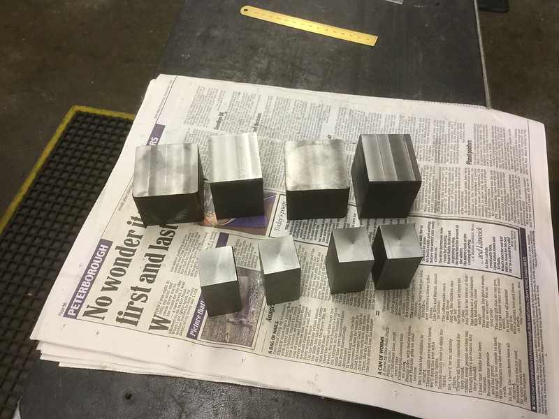 14.12.2016 14.12.2016 by John The Pump, on Flickr All to soon the time had reached 10 pm and we had to stop what we doing and go for a pint in the local. John. |
|
uuu
Elder Statesman
 your message here...
Posts: 2,808
|
Post by uuu on Dec 15, 2016 13:24:27 GMT
One thing we noticed when we had faced off the blocks - you can see it on the last photo, block three - there was a colour variation in the iron. The centre of the bar was different from the edges.
Wilf
|
|
johnthepump
Part of the e-furniture
Building 7 1/4"G Edward Thomas
Posts: 493
|
Post by johnthepump on Dec 16, 2016 17:29:17 GMT
Speaking of noticing things, there see to be a hairline crack on the left hand side of the smaller right hand block. I'll have a good look next time I'm in the workshop.
John.
|
|
|
|
Post by runner42 on Dec 17, 2016 5:21:29 GMT
Speaking of noticing things, there see to be a hairline crack on the left hand side of the smaller right hand block. I'll have a good look next time I'm in the workshop. John. Hi John,
I don't think so if it is a crack wont there be evidence of it on the vertical face as well?
Brian
|
|
johnthepump
Part of the e-furniture
Building 7 1/4"G Edward Thomas
Posts: 493
|
Post by johnthepump on Dec 19, 2016 13:53:05 GMT
Speaking of noticing things, there see to be a hairline crack on the left hand side of the smaller right hand block. I'll have a good look next time I'm in the workshop. John. Hi John,
I don't think so if it is a crack wont there be evidence of it on the vertical face as well?
Brian
Hi Brain, Thanks for your observations on this and you were correct there wasn't a flaw in that particular block. But as I had already seen a fault in a block end, I just assumed it to be that block, goes to show how closely the photo's are looked at. I have started to machine the sides of the small blocks now and the extent of the surface cracking is visible, as there still a lot of material to be removed it is not going to be a problem. John. |
|
johnthepump
Part of the e-furniture
Building 7 1/4"G Edward Thomas
Posts: 493
|
Post by johnthepump on Dec 27, 2016 22:53:17 GMT
Today I decided to take a look at my mill, while cleaning up the cast iron blocks for the axleboxes I noticed one end of the block a few thou. thicker than the other. As the end furthest from the machine body was the thickest I thought there maybe some dirt in the vertical ways. With the aid of the workshop crane I was able to lift off the knee of the mill complete with the X and Y axis, what makes this job easier is the fact this is a turret mill so I was able to turn the head out of the way to allow the lift. After cleaning the ways and clearing out the oil ways and finding a bunged up oil point in the top of the gib strip that I did not know existed, the slide ways were oiled up and the assembly put back together. Tomorrow I will adjust up the gib strip and do some test to see whether there is an improvement. John. 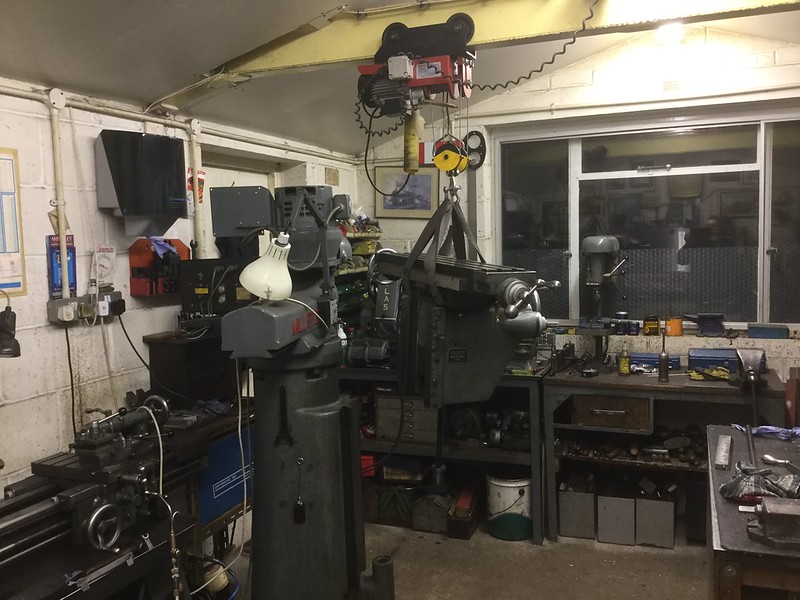 27.12.2016 27.12.2016 by John The Pump, on Flickr |
|
|
|
Post by Roger on Dec 27, 2016 23:35:15 GMT
Hi John,
I suspect it's worn like mine is, with the knee sagging. Hopefully you'll get an improvement by adjusting it, but it probably needs scraping to get it back to how it should be. I'm pretty sure this is the only way I'll get mine really accurate, but in the meantime I'll have to live with it. Fortunately, for most things it probably doesn't matter that much.
|
|
johnthepump
Part of the e-furniture
Building 7 1/4"G Edward Thomas
Posts: 493
|
Post by johnthepump on Jan 6, 2017 13:06:34 GMT
First of all a Happy New Year to everyone, secondly if you say some thing make sure you got it correct. In my case I stated in my 27/12/16 post talking about the cast iron blocks for my axleboxes not being square, I said that the end further from the machine body was larger than the inner end, to that I concluded that there may dirt in the vertical slideway or worse still wear. Having stripped the mill down and cleaned and lubricated Then reassembled it dawned on me from the marks I put on each face of the blocks, that the thicker end was nearer the body of the mill. So although it is good to service machines it was not where the problem lay. In the meantime Wilf had suggested that I used the angle plate that I had used to do the roughing out of the cylinder bores, to square up the blocks. The idea was to set the angle plate up on its side and clocking up in line with the X axis and checking the Y axis, then Z axis up both faces, this was done using the quill feed and then to check by the knee feed these were all satisfactory. Using a machine jack to raise the block surface above the angle plate, the block was clamped against the Y face and with a piece of 1/8" square packing the block was clamp in the X. The top of the block was lightly machined and marked face 2, the block was then reset with the packing discarded with face 1 against the X and 2 to the Y the top face then machined and marked face 3, this process was repeated until al the face had been machined the results were good and got over the squareness problem. 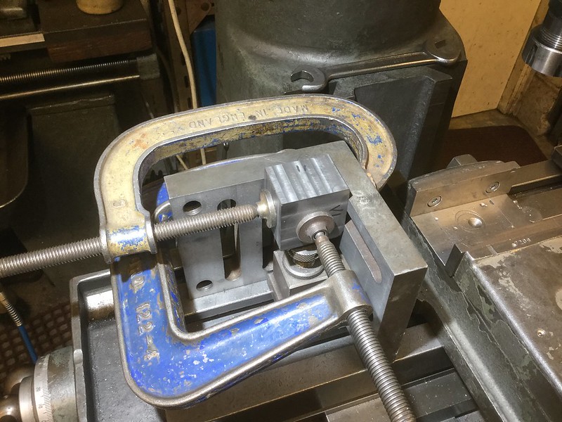 05.01.2017 05.01.2017 by John The Pump, on Flickr This gives an idea of the set up, the angle plate is only stood on the mill for the photo. On checking my machine vice I found the back jaw to be out by about 4 thou. This vice was given to me quite a few years ago from a small firm that I did repairs for, it has a rotary base but I usually leave it off. From the photo it can be seen the this vice has had a hard life with lots of scars, but never look a gift horse in the mouth. The one thing I like about this vice is the fixed front jaw, zeroing the DRO on this all the Y measurements are then positive. Most of the work I have done in this vice has been thin and mounted on parallels, it was not until I started on these axleboxes that I got problems. The Vice was stripped down and cleaned and checked for problems. The first thing I found was the 4 cap screws holding the jaws on needed replacing these had to be made by modifying standard ones. 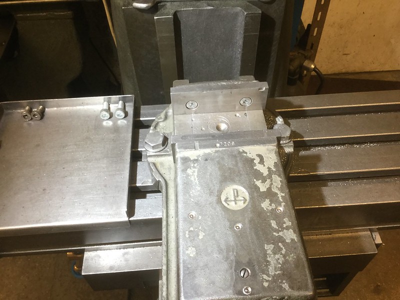 05.01.2017 05.01.2017 by John The Pump, on Flickr Then to deal with the back jaw problem, this vice was reassembled then mounted on the mill and the front jaw clocked true, the centre of the moving deck was clamped down thus holding the back firmly in the slideways, using a 16 mm carbide end mill the back face was trued up. On a day when the weather is warmer I may surface grind the jaws, my surface grinder is in an unheated shed and it takes to long for the bearing to warm up and the motor doesn't like it. 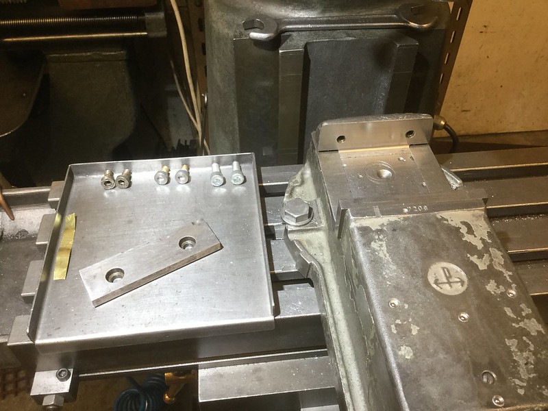 05.01.2017 05.01.2017 by John The Pump, on Flickr |
|
uuu
Elder Statesman
your message here...
Posts: 2,808
|
Post by uuu on Jan 19, 2017 17:31:01 GMT
Wednesday evening report: We drilled and tapped a few holes in my lathe backplate - as I haven't got a 6.8mm drill for 8mm thread (or anything close), and John has. Then I got stuck into making some spacer bars for a wheel quartering jig, while John set up and ran the CNC mill creating some valve handwheels. I can see that a question follows the quartering jig comment - why do we need a quartering jig when the wheelsets are already assembled? Two reasons: The first is a change of direction - John's never been fully happy with the split axleboxes. There's not much meat around the axle, so a solid box would be more comfortable. The second is that there's no guarantee that the axles are correctly quartered to start with - they're as bought. Of course, when John's finished with the jig, I can borrow it for Jessie.  Wilf |
|
johnthepump
Part of the e-furniture
Building 7 1/4"G Edward Thomas
Posts: 493
|
Post by johnthepump on Feb 21, 2017 18:31:43 GMT
The Pumphouse has been slightly on the back burner for a few weeks now. SWMBO suggested that I should get on and finish our main bed room as it had been neglected for far to long, so get on with I did. They came and fitted the carpet last Thursday, the one we ordered and paid for 3 years 11 months ago. It is a long story that I won't go into here, but all the furniture is now ordered, so there is nothing else left for me to do until it arrives, so I can get back to model engineering for a while. Things have been happening in on Wednesday evening, mostly to do with getting Wilf's Myford 254 up and running. But another project that we have been working on is a 7.25" G. quartering jig. The wheels sets for the Edward Thomas I'm building are on 1inch axle instead of 7/8" as called on the drawings. I had intended to make split axle boxes but there isn't enough side room to do this, so I'm going to pull a wheel of each axle and fit ordinary axle boxes. Anyway Wilf thought that the jig would be handy to quarter the wheels on his Jessie when the time comes. Last Wednesday Evening was quite busy. A member ask earlier in the day about mounting a boring bar on the face plate so he could do the smokebox saddle casting for his 5" G. Simplex, I suggested he came over to the Pumphouse that evening and I would lend him (what I believe to be called) a Westbury boring and facing head ( no doubt some one will correct me if I got the name wrong). I mounted it up on the Myford to show how it worked, when he pointed out that the words and music said brackets had to be made to hold the casting in front of the saddle because the cutter radius would not clear the saddle. 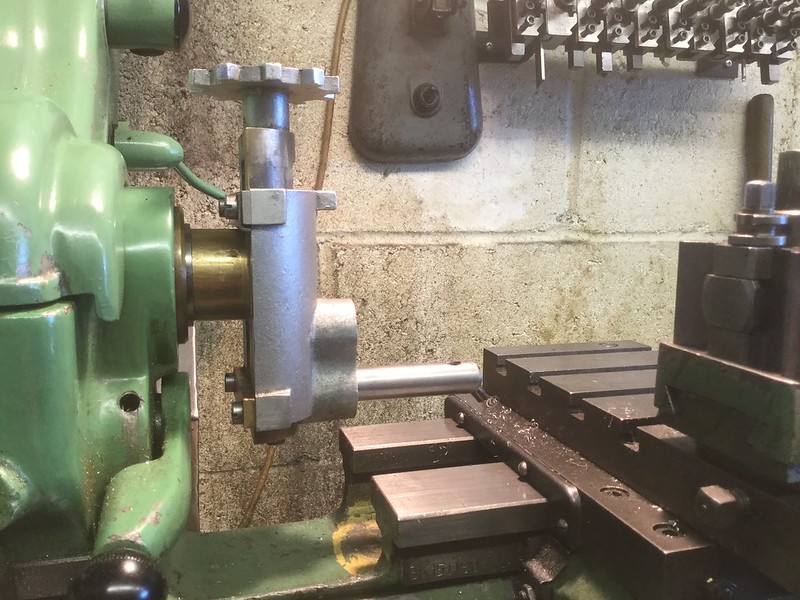 20.02.2017 20.02.2017 by John The Pump, on Flickr I said that It would be better to set the job up in my mill and get on with it there and then 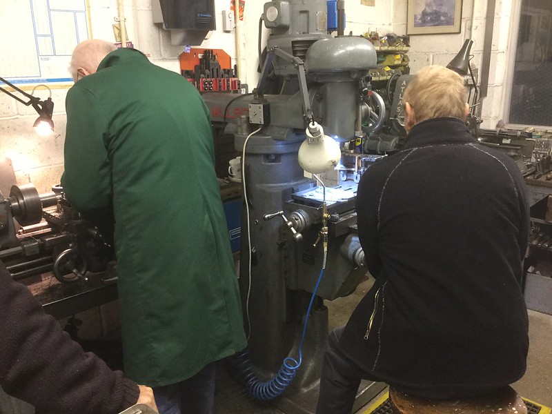 15.02.2017 15.02.2017 by John The Pump, on Flickr So while John S. got on with that, Wilf was busy on the LeBlonde turning up parts for the Quartering jig. 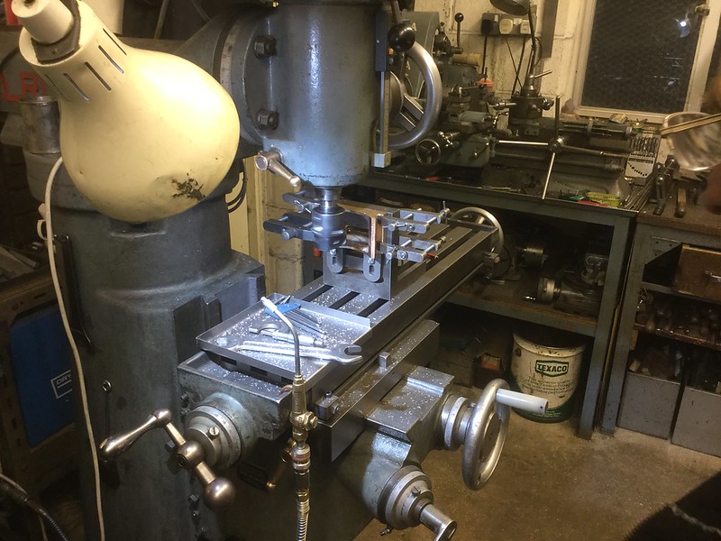 15.02.2017 15.02.2017 by John The Pump, on Flickr A closer view of the set up. |
|
johnthepump
Part of the e-furniture
Building 7 1/4"G Edward Thomas
Posts: 493
|
Post by johnthepump on Mar 3, 2017 11:12:23 GMT
This Wednesday evening saw the completion of the 7 1/4"G. quartering jig. With the exception of the eight 8 mm. nuts and the E rings (type of circlip) all the other material for this jig came the boxes under the bench, that we all keep as it may come in handy. 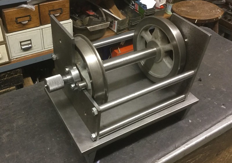 01.03.2017 01.03.2017 by John The Pump, on Flickr The Jig with one of my wheel sets in it, stood on my small surface plate. When the need arises I will make another set of spacer rods for 5"G. as this jig is much more robust than the 5" one I built in a hurry many years ago, The centre point adjuster are screw cut 3/4" x 12 tpi BSF and the centres are made of silver steel sliding in bored and reamed holes. In use the jig will be clamped down onto the mill table, to make sure it remains square. 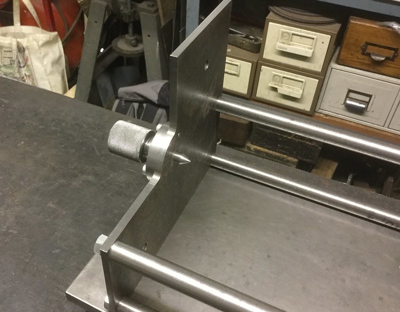 01.03.2017 01.03.2017 by John The Pump, on Flickr Close up of one of the centring units. |
|
johnthepump
Part of the e-furniture
Building 7 1/4"G Edward Thomas
Posts: 493
|
Post by johnthepump on Mar 7, 2017 21:46:25 GMT
A little job I did today was to make a couple of odd shaped ferules to repair some control knobs. A club members had dropped by yesterday to discuss a project he wanted a second opinion on, after which he asked what could I do to repair these control knobs, off a piece of equipment that was 25 years old and still in good condition except for the knobs. Last evening I drew this up and sent a preview image of the job, neither of us noticed the I had that I had made a mistake. Not only that but I went onto machine it. So it was back to square one and redraw the job and re-machine. 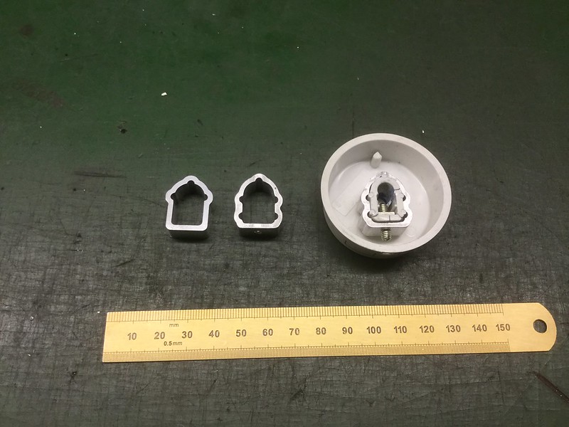 06.03.2017 06.03.2017 by John The Pump, on Flickr These ferules are 10mm deep and were machined using a 3mm single flute carbide cutter running at 9000 rpm. 1.2mm cut depth and a feed rate of 60 mm/min. John. |
|
johnthepump
Part of the e-furniture
Building 7 1/4"G Edward Thomas
Posts: 493
|
Post by johnthepump on Mar 20, 2017 10:48:07 GMT
The other day I was looking on the local social media and came across someone who was looking for some door knob spindles as their doors were thicker than the modern door and therefore the spindles that came with the purchase of new door knobs were to short. They had tried to get it touch with the supplier and got no response. These spindle were threaded and they were thought to be 6 mm, someone suggested studding, but they dismissed that idea, as it needed to have a thread on the bits they required.!!!? Anyway I posted that I may be able to help and in due coarse the spindle that required replacement arrived at the Pumphouse. The thread turned out to be 3/8"x16 UNC and the square 5/16", they required 2 at 140mm and 4 at 120mm. As I had some 12mm stainless steel short ends in the box under the bench I made them out of that. I was lucky to find a set of 3/8"x16 UNC die bits in my collection and set up the Coventry die box on the capstan on my Atlas lathe to put the thread on. John. 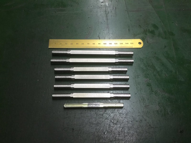 19.03.2017 19.03.2017 by John The Pump, on Flickr |
|
johnthepump
Part of the e-furniture
Building 7 1/4"G Edward Thomas
Posts: 493
|
Post by johnthepump on Mar 22, 2017 11:48:20 GMT
Tuesday Evening in the Pumphouse, When I was sat in the clubhouse having lunch last Saturday A member who is in his nineties sat down and reached into his pocket. As he put out his clenched hand he said here is a little job, that I trust you can do. I t was a pair of garden gauge loco driving wheels that he wanted the flanges machining off. He went on tell us about his days at Guildford shed working his way up from cleaner through the ranks to driver and how enjoyed driving the 2-6-2 Mongolipers. When he return to the Island after the war he rejoined the Isle of Wight railways as a driver a position he would not have made had he stayed. I haven't come across wheels with square axle holes before, anyway I made a small fixture to mount the wheel on and machined off the flange and the tread angle as required. John. 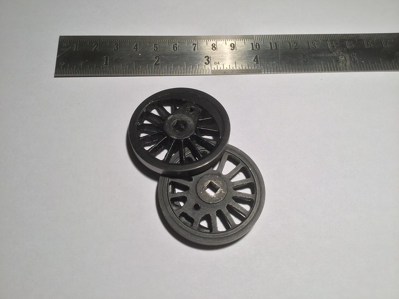 21.03.2017 21.03.2017 by John The Pump, on Flickr |
|


