|
|
Post by steamingmess on Mar 22, 2017 21:08:22 GMT
Hi john.
May I ask who this was?
Dan
|
|
jma1009
Elder Statesman

Posts: 5,901
|
Post by jma1009 on Mar 22, 2017 21:40:13 GMT
Hi John,
Yes, I was also thinking the same as Dan!
The only ex Guildford Depot footplate crew I know of who moved to the IOW and became an IWMES member is George Taylor.
In the mid 1960s he was a fireman on steam at Guildford MPD. He was never passed as a driver of steam, and certainly never worked on the IOW railways.
I remember George telling me to 'water' all my coal in the tender of one of my miniature locos "because that is what we did at Guildford MPD". I asked why. He replied "wet coal burns better in a firebox due to the hydrogen and oxygen in the water".
I realised at that point that George could never have been a good fireman on a steam loco, and all his other stories needed hefty dollops of salt!
He carefully avoided many invites to drive any of my miniature steam locos, which was odd from an ex BR footplateman.
Cheers,
Julian
|
|
|
|
Post by steamingmess on Mar 23, 2017 7:52:06 GMT
Hi Julian thanks for that.
The only reason you wet the coal is to keep the dust damp so it doesn't go everywhere. Helps to keep the footplate clean.
I have had the odd story from George.
Dan
|
|
johnthepump
Part of the e-furniture
 Building 7 1/4"G Edward Thomas
Posts: 494 
|
Post by johnthepump on Apr 21, 2017 9:47:01 GMT
Progress on my loco seems to have been a bit slow lately what with stopping to make the wheel quartering jig, having done that we then took one wheel of each axle and then a decision was made to press out the crankpins which were for marine rods. I have always wanted to make post 1977 flat rods that Edward Thomas now features. The axle boxes are now made and in place temporally as they still need the side clearances sorting out. One problem that occurred the wheelsets had a back to back to the 7 1/4" G. Society recommended narrow gauge measurement of 6.750" and my chassis made to the Reeves drawing measures 6.800" across the axle boxes, so the axle boxes were reduced by 0.030 on the faces this now give a side float of 10 thou. I was lucky enough to get hold of a length of BMS bar 4 foot long 2 1/4" wide and 1/2" thick, which is ample, the chalk marks give a rough outline of a coupling rod. I'm making drawings from photos, after that there is going to be a lot of drill, saw and hack to get the rough blanks out of the steel. John. 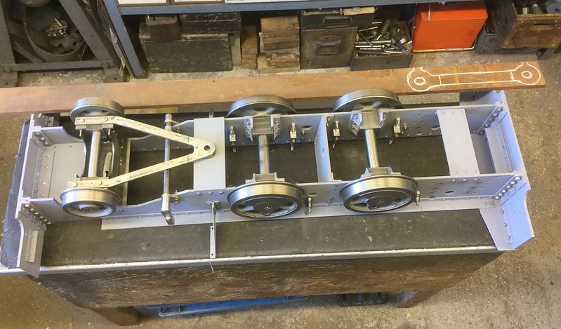 20.04.2017 20.04.2017 by John The Pump, on Flickr |
|
johnthepump
Part of the e-furniture
Building 7 1/4"G Edward Thomas
Posts: 494
|
Post by johnthepump on Apr 30, 2017 15:30:25 GMT
Wednesday evening we decided to put the clearance radius in the axle boxes. Wilf suggested instead of my thoughts of making a fixture to hold the boxes, why not just use a piece 1" bar through 2 boxes and clamp down between them with the box to be machined against a line and the bar on the centre line. I have a plate that the clubs Super Simplex expansion links were machined on over 20 years ago now and it has been used for all sort of jobs since, so that was our starting point for this job. We managed to machine 2 arcs before the call of the barmaid (10 pm), other thing have taken my time until today when I decided to make the fixture have a register as the block isn't easy to line up after the curve has gone in on the first side, also mods had to be made to allow clearance for the inner edge of the boxes which are wider than the outer one. 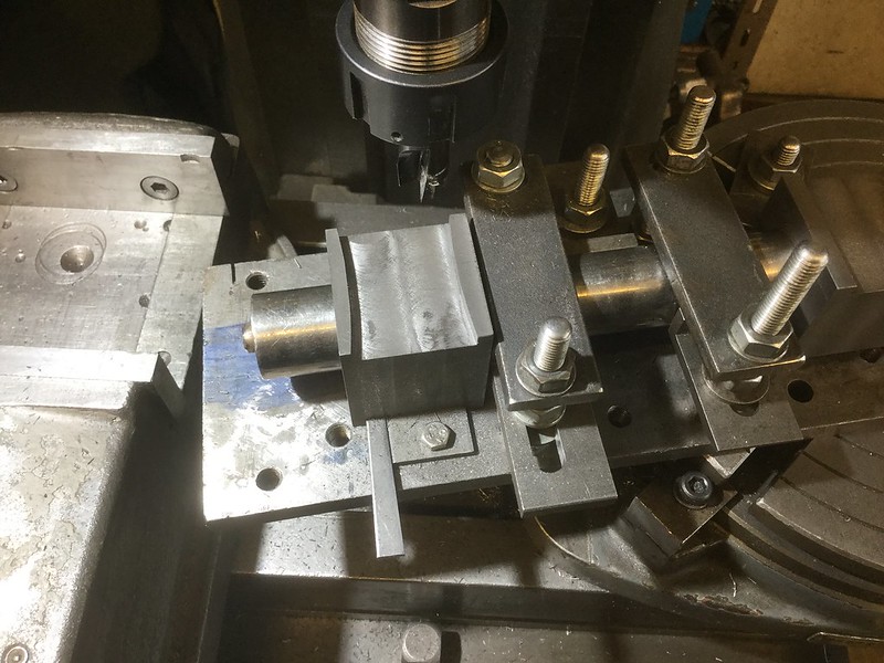 30.04.2017 30.04.2017 by John The Pump, on Flickr The 1" bar is held in position on the centreline by the three inverted clamps and the axle box registers against the thin plate and the thin key holds it onto reference while the hold down clamps are tightened, I also fit a toolmakers clamp on the axle box for added clamping. The picture bellows show the fixture with the clamps removed. John. 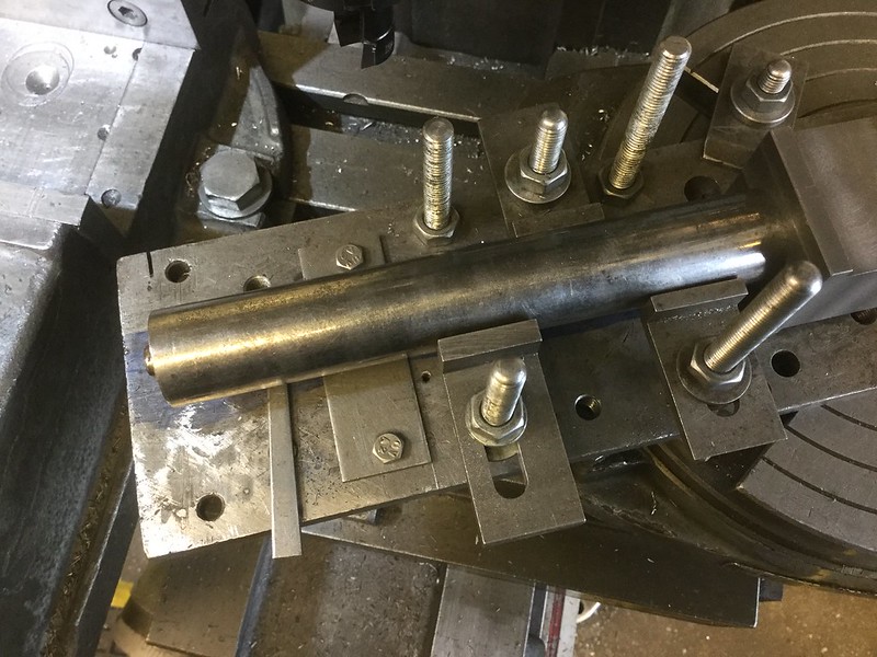 30.04.2017 30.04.2017 by John The Pump, on Flickr |
|
|
|
Post by Deleted on Apr 30, 2017 15:40:51 GMT
I do like that John and good timing too as just a few days ago I was making notes of what needs doing once I've stripped the frames down for painting...and this is one of the items on the list...perfect timing...I'll have a route around the metal bin to see what I can use to make the jig...I'll need to get another length of 7/8 silver steel too but nothing too expensive....  cheers Pete |
|
uuu
Elder Statesman
your message here...
Posts: 2,812
|
Post by uuu on May 26, 2017 7:51:08 GMT
Wednesday evening was busy at the Pumphouse. John had a brainwave to get his coupling rods dead on size. The OD of the bearings is bigger than the axle size. So over the last two weeks we've bored the holes in the blanks to fit on the axles. Now they fit right, the holes can be enlarged up to bearing size. But first (so the plan was) the outside profile would get machined. Before we could get going on that, I did need a small job done on my Slate Waggon. Here's progress so far on the pedestals. I'm pleased with how these have turned out. 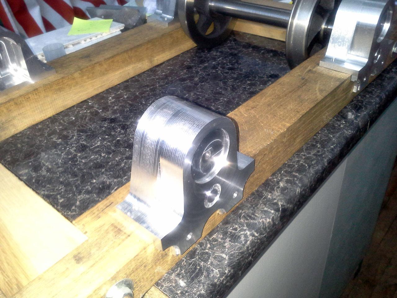 WaggonChassis WaggonChassis by Wilf, on Flickr You'll see they're in aluminium, rather than cast iron. So I've made cut-outs in the axlebox pockets, and plan to fit steel rubbing plates either side. I had some left over from Jessie, that had distorted a little when hardening. Here they are after John flatted them off on his surface grinder: 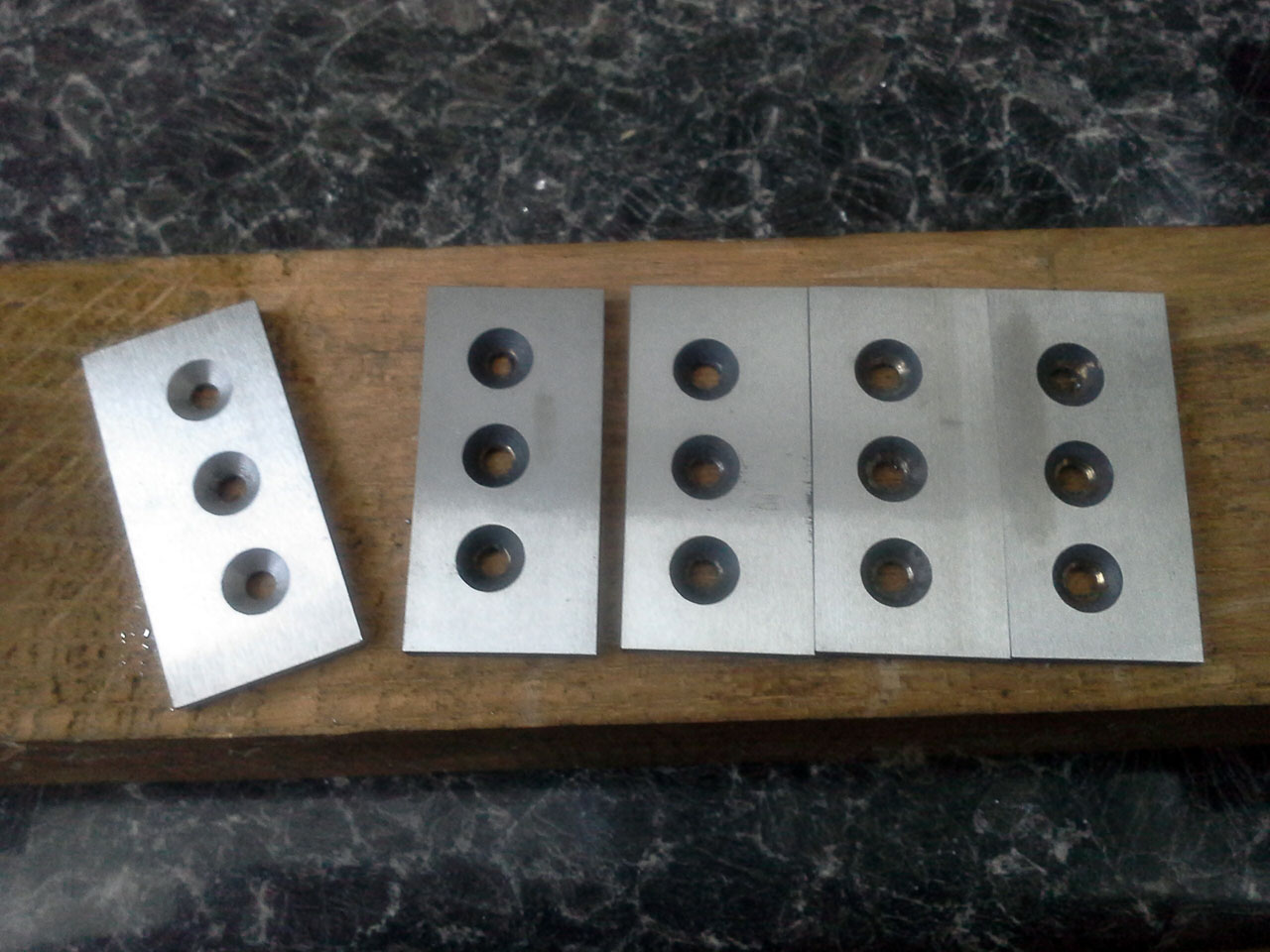 WaggonCheeks WaggonCheeks by Wilf, on Flickr A visitor had brought in the chassis for his "Single". It's going to be a lovely loco (all his turn out well). He's the kind of man who wears white clothes to the Pumphouse! Anyway, he was concerned that the chassis was a bit "banana". So John set it up on the big surface table with packing blocks and angle iron. It seems to be fine. The plates are quite thin, and there aren't many stays to keep things all square. But it should pull up straight in the end. The cylinder block is a lovely thing. We had some discussions on a member's new "Speedy". He was having trouble getting the safety valve right, and the loco seized when warm. We've supplied him with a Gordon Smith valve drawing from Polly, that ought to work right. As to the seizing up: the piston rings are a thing of wonder - home-made Clupet style. But he's made the pistons in aluminium! So they're expanding too much. Eventually we did get on to John's coupling rods. No metal was cut - but the set up in the mill was progressed. This will be on the rotary table to get the ends to shape. Wilf |
|
mbrown
Elder Statesman
Posts: 1,720
|
Post by mbrown on May 26, 2017 15:37:36 GMT
I'd love to know more about the homemade Clupet rings. I've examined them in full size and just can't work out how they're made - let alone in miniature...
Malcolm
|
|
|
|
Post by Roger on May 26, 2017 19:33:38 GMT
I'd love to know more about the homemade Clupet rings. I've examined them in full size and just can't work out how they're made - let alone in miniature... Malcolm From what I can gather, it's not quite as magic as it would seem to be. Slitting them isn't really a problem, but getting the slits to close up afterwards seems impossible at first glance. If you force the ring up and over the part it's supposed to be pressing against, it will bend. When you bring it back to the right side again, it will spring against that face and close the gap. Obviously if you overdo it, a CI ring will snap, but I believe it's just elastic enough to cope with this rather brutal abuse. If anyone can correct me on this, I'd be interested to hear from them. |
|
mbrown
Elder Statesman
Posts: 1,720
|
Post by mbrown on May 26, 2017 19:47:48 GMT
That makes sense Roger - they look a bit like key rings, and I imagine that's how key rings are made. Doing it with brittle cast iron must be the tricky bit!
Malcolm
|
|
|
|
Post by Deleted on May 26, 2017 20:12:30 GMT
Doing it with brittle cast iron must be the tricky bit! Malcolm I have no experience with steam loco piston rings other than the PTFE ones that I made for 4470 but I do have a fair bit of experience for piston rings on car engines. These are also cast iron and very strong, you'd have to really push to break them. When I rebuilt the engine on my classic Porsche 2 years ago, which now has 'full race' spec pistons fitted, I had to work out the gap according to expected heat generated at full power. This meant discarding the gap's specified by the manufacturer and calculate my own for an engine that was literally doubling in power output. Don't worry, I did get confirmation that my calculations were correct from the piston manufacturer technical department in Argentina. I think two years of good running says I and the tech team got something right...anyway the point of my rambling was just to say that cast iron rings have a fair amount of latitude when being handled...well they do on a car engine... regards Pete |
|
rrmrd66
Part of the e-furniture
Posts: 339
|
Post by rrmrd66 on May 28, 2017 20:29:09 GMT
Evening everybody
Don't know if the following is helpful, but here goes.
Foe many years my company was the exclusive UK distributor of a cast iron sealing ring used on tracked vehicles etc. (Known more commonly as a "Caterpillar" seal).
They were made of a very hard, yet flexible, cast iron by a the Goetze company (pronounced Gurtza) of Burscheid, Germany (now part of the Federal Mogul Corporation).
Their major product line however was piston rings supplied to all the major German car manufacturer. They also supplied marine diesel engine manufacturers. So, quite a range.
On my many visits to their foundries I was always fascinated by the amount of machining work that went into making one cast iron piston ring.
They were sand cast not round but "oval". All piston rings were cam turned "oval" and gapped to a shape that upon being compressed into the cylinder bore the gap would close to the required dimension and the piston ring would become round.
I recall something like an oil control ring went through something like 28 different turning and milling operations, normally held in a jig that gripped 20 or 30 rings, depending upon size.
Hope this was of interest
Cheers
Malcolm
|
|
johnthepump
Part of the e-furniture
Building 7 1/4"G Edward Thomas
Posts: 494
|
Post by johnthepump on May 30, 2017 11:25:38 GMT
Hi Malcolm,
Thanks for your interesting post on piston ring manufacture, I for one had never giving any thought how these were made, all over the world there must millions of piston rings going up and down cylinders bores at any one time.
Regards John.
|
|
johnthepump
Part of the e-furniture
Building 7 1/4"G Edward Thomas
Posts: 494
|
Post by johnthepump on May 30, 2017 11:57:33 GMT
Over the Bank Holiday Monday I found time to do a little more to No. 4's coupling rods, using a 16mm carbide insert endmill, I machined the 0.875" radius on both ends of one of the rods. The cuts were 0.050" deep and the RPM was 1200, It took ten cuts and then a reposition to cut up the side of what will become the oilway. I will do the other rod to the same place and then start on some co- ordinate chain drilling to remove some of the bulk waste metal, my thoughts on this is to drill 4mm holes on a 5mm pitch then open out every other hole to 5mm and the whole thing should break away. In the mean time I have got another club bogie to repair this time 7 1/4"G as can be seen from the photo we have just done another 5" G. one Regards John. 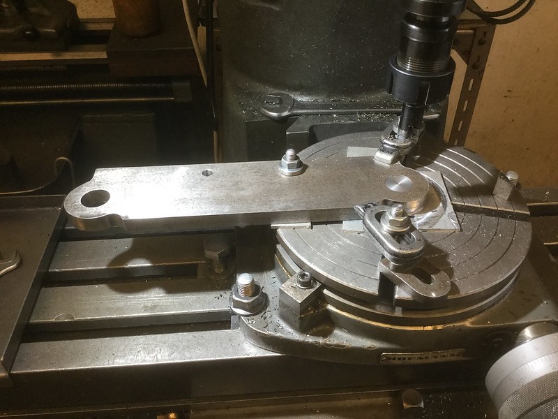 29.05.2017 29.05.2017 by John The Pump, on Flickr 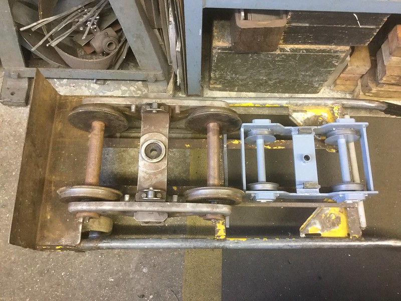 29.05.2017 29.05.2017 by John The Pump, on Flickr The little odd shaped thing underneath my cutter grinder is a casting mold for making lead hammers, a piece of iron water pipe with its end flattened is fitted in the mould on the other end of the mould is a ladle in which to melt just the right amount of lead. |
|
johnthepump
Part of the e-furniture
Building 7 1/4"G Edward Thomas
Posts: 494
|
Post by johnthepump on Jun 11, 2017 9:04:39 GMT
Further progress on the coupling rods for No 4, with the ends done the next job was to remove the material from the underside. This was done in 10 passes 50 thou deep. 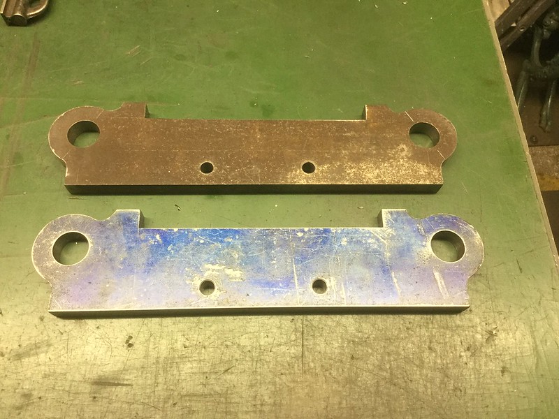 09.06.2017 09.06.2017 by John The Pump, on Flickr Then the next job was to chain drill to remove the bulk of the material from the topside as I said in my last post, this was going to be done in 5mm steps using a 4mm drill then opening out to 5mm on the drilling machine, the X preset can be seen on my old Anilam. 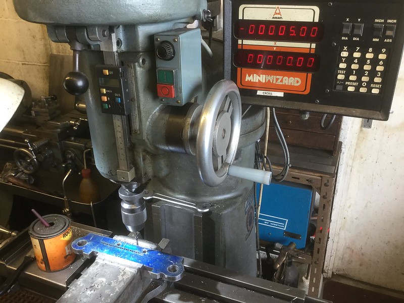 09.06.2017 09.06.2017 by John The Pump, on Flickr Then using a 1mm cutting disc in the angle grinder the waste was cut away. 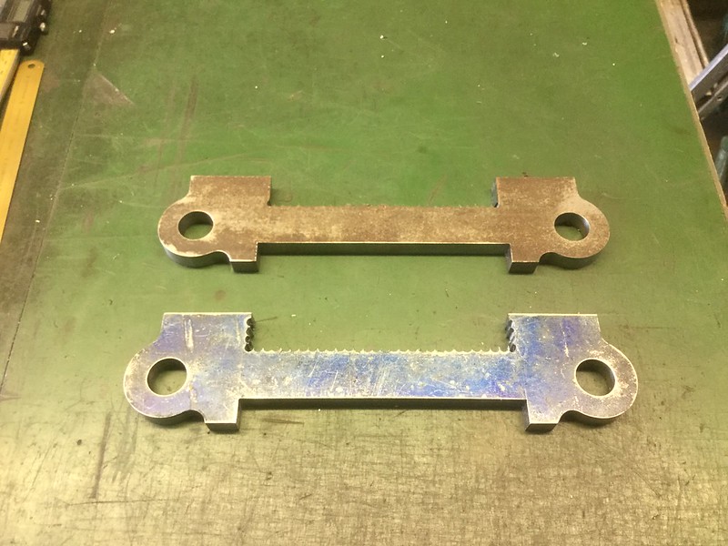 09.06.2017 09.06.2017 by John The Pump, on Flickr There is still a lot more to do and the blending radii are going to need some jig work to position the rod in the correct place on the rotary table. |
|
johnthepump
Part of the e-furniture
Building 7 1/4"G Edward Thomas
Posts: 494
|
Post by johnthepump on Jun 25, 2017 9:27:14 GMT
Wednesday evening saw the finishing off of the fixture plate to mount the coupling rods to do the next 2 curves. While I mounted the plate on the rotary table and clock it up. Wilf set to and made the 2 buttons that register in the holes in the rods. 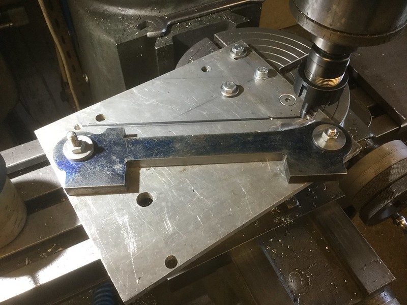 24.06.2017 24.06.2017 by John The Pump, on Flickr The above photo shows the 2nd rod with the first end part machined for the first curve, the black line joining the 2 M8 tapped holes is the position to put the curves to the other side. 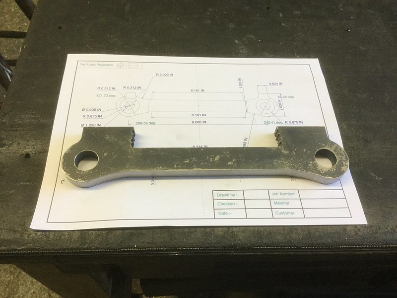 24.06.2017 24.06.2017 by John The Pump, on Flickr With a little cleaning up the first rod is beginning to take shape. Progress is slow at this time of year as the gardening take a lot of time. John. |
|
johnthepump
Part of the e-furniture
Building 7 1/4"G Edward Thomas
Posts: 494
|
Post by johnthepump on Jun 30, 2017 19:34:27 GMT
Further progress was made on Wednesday evening to the coupling rods. 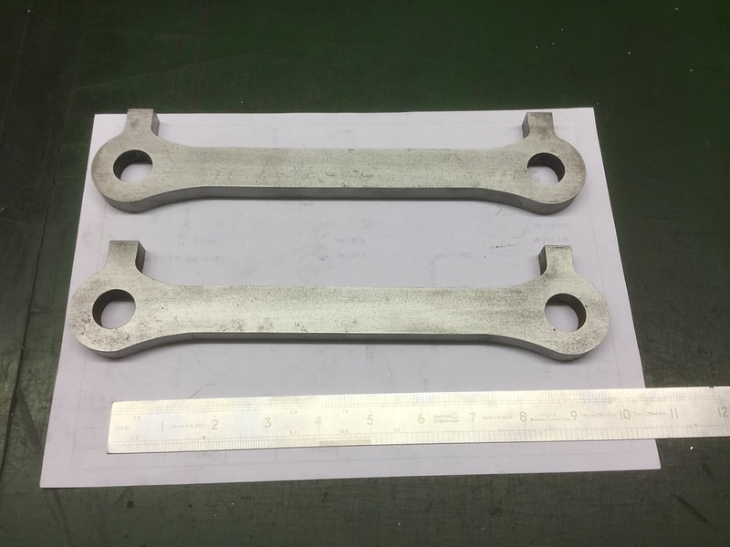 29.06.2017 29.06.2017 by John The Pump, on Flickr They are beginning to take shape, the next step is to thin the sides followed by a lot of tidying up and polishing. John. |
|
johnthepump
Part of the e-furniture
Building 7 1/4"G Edward Thomas
Posts: 494
|
Post by johnthepump on Jul 19, 2017 18:21:51 GMT
Last Wednesday evening was spent working out the requirements for crankpins to take the type of coupling rods that we are making and checking that there would be room. Towards the end of the evening we set up the mill so to thin the coupling rods, due to other things and a cold I had not done anything further. Tuesday evening arrived and I was back onto helping our club Secretary with repairs to his B1's tender, he had taken decided to replace the axle box springs, unfortunately when he dropped the wheelsets out the wheels all fell of the axles. We set about boring the wheel centers the Tuesday before last and as the job was set up in the Myford, When Wilf arrived on the Wednesday evening He saw it sense to finish all six wheels before we got with bits for my loco. the following Tuesday the axle boxes were rebored and a light facing cut taken. This Tuesday evening the axle boxes had a small chamfer machined on them and an oil hole drilled. I managed to set this up on the mill without removing my coupling rod set up. 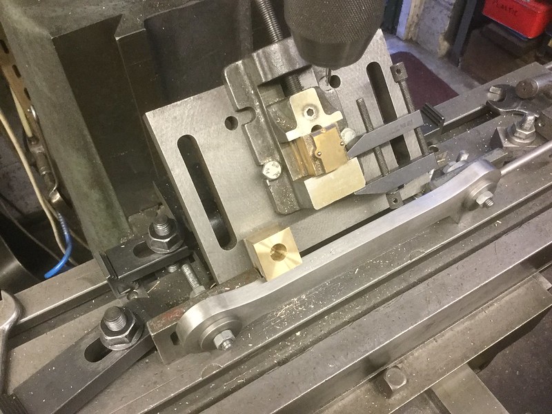 18.07.2017 18.07.2017 by John The Pump, on Flickr Before the evening was out I just had time to cut the new axle blanks and clean the ends up and centre on end in readiness for next Tuesday evening session on the repair. I'm signing off now as the lads are turning up for this evening session in the Pumphouse. John. |
|
uuu
Elder Statesman
your message here...
Posts: 2,812
|
Post by uuu on Jul 20, 2017 6:03:13 GMT
And what a good evening it was. Only John got actual work done - attacking his coupling rods with a ripper cutter...
..while Mike and I tried to convince a member that it wasn't his fault that he drove his Speedy over a mains cable. What kind of idiot decides to cut the hedge when there are trains circulating? We're minded to mount a 5 inch slice of cable on a board as a trophy.
Discussions on couplings, height gauges.
Wilf
|
|
johnthepump
Part of the e-furniture
Building 7 1/4"G Edward Thomas
Posts: 494
|
Post by johnthepump on Jul 20, 2017 17:30:10 GMT
As Wilf said in the previous post I got on with No.4's coupling rods using a ripper cutter to remove most of the metal as seen in the photo below. 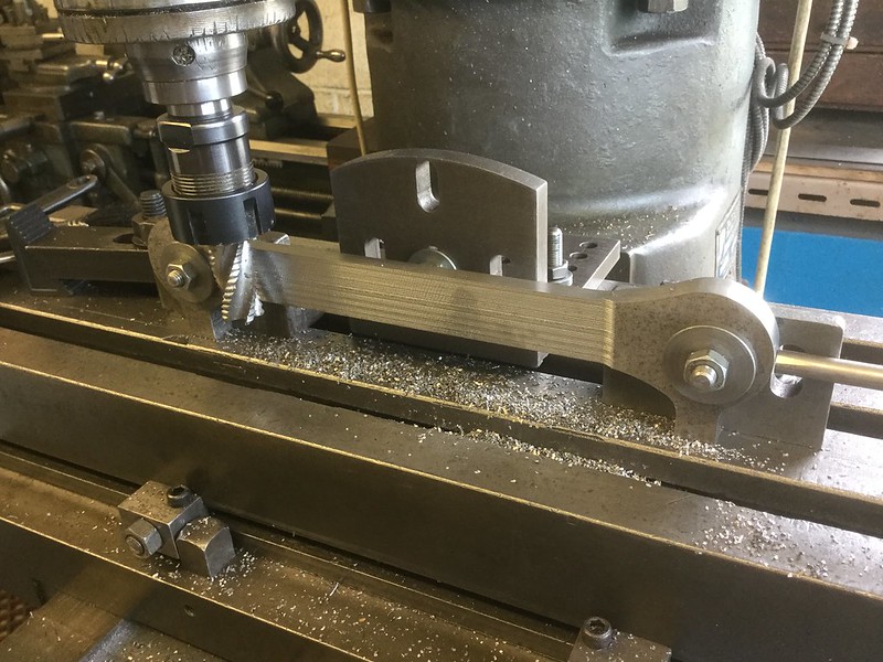 20.07.2017 20.07.2017 by John The Pump, on Flickr The cutter was then changed to an end mill to take the final 10 thou. cut. 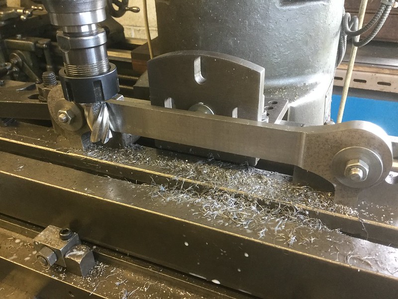 20.07.2017 20.07.2017 by John The Pump, on Flickr I am now off to a club meeting, tonight's subject is Bits and pieces, so I will take some of the things that we have done in the Pumphouse over the last few months. John. |
|


