|
|
Post by 92220 on Mar 7, 2021 10:39:19 GMT
Hi Folks. Sorry I haven’t added anything to my thread recently, but I have been very busy. I have had major problems that needed sorting. The problem was that the mouldings I had made for the front top corners of the firebox clothing were the wrong shape and I have had to completely remake the inner clothing sheets. I’ve lost almost a years work but the replacements are all, now, to the B.R. drawings, in shape. In remaking the inner clothing sheets, I’ve also had to remake the outer clothing sheets, made from 0.008” steel shim. I have just realised |I haven’t posted anything, yet, about making the clothing, so I will start to sort that after posting this. I have a load of photos, but they all need reducing in file size, to add to Flickr, so it will be a week or so. As well as replacing all the clothing sheets, I have experimented with pressing the rather complicated shaped moulding between the lower front of the firebox and the underside of the boiler barrel. I made a male and female press tool, out of large section aluminium bar. First off I tried forming the pressing in 0.5mm nickel silver sheet, as used for the rest of the inner clothing. That didn’t work because, no matter what I did, I couldn’t soften the sheet very much at all. Next I tried 0.5mm brass sheet. I couldn’t get that as soft as I needed. I possibly have the wrong spec brass. I still got unacceptable creases in the corners. Years ago, when I worked as a design draughtsman for a company that closed down, I bought a full sheet of 0.5mm copper sheet for £1.00!!!. It has been sculling around the workshop since 1990!!! I cut sheets of that and annealed them by getting red hot and cooling slowly. These worked a treat!! I got good forms in both directions. I won’t go into how the pressing was done, until I write up the making of the clothing, next. Having remade the clothing sheets, I came to making the boiler band that fits to the front of the firebox. I had to silversolder some L-shaped brackets to the ends of the band, to be able to tighten it in place. The last time I silversoldered the screw brackets to the ends of bands I had a job holding them all together. This time it was easy! I remembered something that Roger mentioned in his 15xx thread, about silversolder not adhering to titanium. I decided I must make some new toolmakers clamps, in titanium, so that I could clamp parts and not worry about the clamps being soldered to the job! I found someone on Ebay, selling 8mm square x 20” long lengths of titanium rod, at a very reasonable price, and in UK! I can’t remember how I first learned that titanium can burn, a bit like magnesium, and that got me somewhat concerned that I was doing something utterly stupid! I did some digging on the ‘net and found out that it really can catch fire. So was it a bad idea to make the clamps in titanium? I had to find out, and quick!! I cut a 1/8” length off the end of the 8mm square bar and put it in the middle of the brazing hearth. I also got the CO2 extinguisher ready!! I lit my oxy propane torch and played the flame on the titanium square. The corner nearest the flame glowed white hot and had a slight sparkle. The rest quickly got up to red heat and I kept it in the flame for about a minute. The result……nothing!! I took the flame away and it just cooled down like any normal lump of steel!! So, although titanium has the ability to burn (according to the internet), I couldn’t make it burn, even in an oxy-propane flame. That decided me that titanium clamps for silversoldering parts, were safe (but will keep the extinguisher next to the brazing hearth in future. This is the result….2 clamps so far, with material to make a further 3 clamps. They are the same size as the Eclipse 2” clamps:-  Img_4564 Img_4564 by Robert Shephard, on Flickr  Img_4566 Img_4566 by Robert Shephard, on Flickr 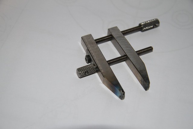 Img_4565 Img_4565 by Robert Shephard, on Flickr The one problem with titanium is that it is not easy to machine. I found it best to use new carbide endmills to get a good finish on the rods. HSS is OK but you need new, very sharp cutters and a slow speed….about half the speed for BMS. The titanium rods don’t come in bright, and smooth, like bright mild steel rods. They almost look as if they have been cast. Anyway, I had to machine the rods all over to get them smooth and decent appearance. I used a 12mm endmill running at around 1000 rpm, and a slow feed (don’t know what). It produced a lovely smooth finish. The metal actually cut easier, with carbide cutters, at speeds generally used for HSS tools . Tapping was the biggest headache. I tapped them 4BA for the clamping threads. The recommended drill is 3.0mm but I found it necessary to use a 3.1mm and for the second clamp I used 3.2mm drill. Titanium does not like being tapped. I used Rocal RTD compound/liquid, as a tapping lubricant as it felt as if the tap might jam and break if dry. The clamp screws are made of mild steel studding, threaded into mild steel thumb knobs, locked on with Loctite 290. I expect the silversoldering heat won’t ever get to the thumb knobs. They will just get a bit too hot to actually hold, so Loctite should be fine. We shall see!! The one clamp shows heat discolouration because it was used to silversolder the end clamps on the boiler band. Bob. |
|
|
|
Post by Roger on Mar 7, 2021 11:55:53 GMT
Hi Bob,
That's really interesting and a useful insight to working this metal. The clamps look like a very useful addition to the workshop. My Steel ones have suffered from the heating they've got, and Titanium ones would definitely be an improvement.
|
|
|
|
Post by 92220 on Mar 7, 2021 13:27:13 GMT
Hi Roger.
I've only used them a couple of times so far, but they work really well with nothing sticking to the clamps. I made the clamping screws out of mild steel studding Locktited into BMS knurled knobs. As I said above, the studs are 4BA. They could just as easily be 3mm or 4mm, but with either thread I wouldn't tap in deeper than about 10 to 12mm, so that there is a solid portion of knob that can have a 1/8" or 3.5mm cross hole drilled for a tommy bar. I don't envisage a tommy bar being needed though, for silversoldering work, but if the clamps stay in decent condition, they can be used for normal clamping as well. It will be interesting to see how they stand up to the high temperature use. Like you, I have spoiled a number of small clamps, but they are the ones I bought cheap, and quite prepared for them to be spoiled for normal use.
Bob.
|
|
kipford
Statesman
 Building a Don Young 5" Gauge Aspinall Class 27
Posts: 566 
|
Post by kipford on Mar 7, 2021 13:43:20 GMT
Bob
Titanium does burn like magnesium but it takes a lot to get it going. All the aerospace manufactures use it as fire walls it has to meet a 30 minute containment requirement. Machining can result in fires and most machine shops who process it have buckets of sand around in case of a fire. I think it is a bit like flour where in powder form it is highly combustable.
Dave
|
|
|
|
Post by 92220 on Mar 7, 2021 14:53:10 GMT
Hi Dave.
Thanks for that info. It's interesting that titanium, although flammable, is used as a fire wall. I did read that it burns like magnesium. However, I found it doesn't ignite quite as easily. I can remember as a teenager, being sent out of our chemistry lesson because I stuck a strip of magnesium in a bunsen burner flame. Yes. I now know what magnesium burns like!!!! However, the Titanium I have may be an alloy, although they listed it as 'pure'. It glowed white hot in my oxy-propane flame, which is much hotter than a bunsen burner, and it didn't ignite. Even the tiny shaving that was left when it was sawn off the rod, only glowed and sparkled, but it is still there and there was no flame evident. I have read that titanium alloys are far more fire resistant than pure titanium, but what alloys, I have no idea. They didn't say. All I can say is, I am very well aware of the warnings and will always take precautions, and have either sand or CO2 next door to the hearth; though I should do that anyway. Lesson learned. On your point about the flammability of titanium powder, yes I am also very conscious of that danger though there would be no titanium dust anywhere near the hearth. It's like iron powder and aluminium powder (Thermite), mixed, burns and is almost impossible to extinguish, even though we all know the base metals are non-flammable.
Bob.
|
|
oldnorton
Statesman
5" gauge LMS enthusiast
Posts: 693
|
Post by oldnorton on Mar 8, 2021 14:26:42 GMT
The clamps are very interesting Bob, thank you. I guess there must be a big difference in the machinability of pure titanium and its various alloys, just like we experience with the steels and bronzes.
I have used titanium wire for hanging items being electroplated as well as the anodes. For some reason relating to where it is on the electrochemical scale it is very chemically resistant.
Regarding its likelihood of catching fire, in truth all metals that can oxidise will react if there is enough oxygen, it is hot enough and, I learnt many years ago, it is fine enough such that its surface area is high in relation to the mass of the particle. Magnesium alloy sounds quite combustable but apparently it is impossible to make a small lump catch fire in the workshop. However, Navy ships made of aluminium seem to burn up when Exocet missiles hit them so perhaps some caution is wise.
Norm
|
|
|
|
Post by robgreenwood2018 on Apr 30, 2021 20:31:20 GMT
Just stunning! It just goes to show that with time and unbelievable skill you can create a true replica of such a fantastic machine.
Thanks for the photos and inspiration!
|
|
sis
Seasoned Member

Posts: 113
|
Post by sis on May 2, 2021 17:59:51 GMT
Hi Bob,
What grade of titanium did you use?
Thanks
Steve
|
|
|
|
Post by 92220 on May 2, 2021 22:26:30 GMT
Hi Steve.
I don't know what grade I bought but this is the description from the listing on ebay:-
High Intensity Purity TA2 Ti Bar.
It came from China (like everything!!), and was a listing for 20" lengths of 6x6 to 12 x 12mm square stock.
Hope that helps.
Bob.
|
|
sis
Seasoned Member
Posts: 113
|
Post by sis on May 3, 2021 16:51:54 GMT
Hi Bob,
I think that is a pure grade 2 titanium.
I will be making some of these. Many thanks for the idea.
Thanks,
Steve
|
|
|
|
Post by 92220 on May 4, 2021 9:41:29 GMT
Hi Steve.
The square bars, when they arrive, don't have the finish you expect, so will need all-over machining. The bars almost look like a cast finish rather than the expected drawn finish....nowhere near as smooth as one would expect. I used carbide cutters and had no trouble machining. The tapping of the holes was a bit more difficult with HSS taps. I used a one size larger tapping drill to make it easier to tap. The Ti clamps make silversoldering very much easier as you don't have to worry about silversoldering the clamp to the job!!
Bob.
|
|
|
|
Post by ettingtonliam on May 4, 2021 12:47:46 GMT
I keep a few old clamps, deliberately very rusty except for the adjusting screws, so nothing sticks to them either.
|
|
Gary L
Elder Statesman

Posts: 1,208
|
Post by Gary L on May 4, 2021 13:00:13 GMT
I keep a few old clamps, deliberately very rusty except for the adjusting screws, so nothing sticks to them either. Yes, and steel is fairly poor (in a good way) as a heat sink. How does Titanium compare for conductivity I wonder? Gary |
|
kipford
Statesman
Building a Don Young 5" Gauge Aspinall Class 27
Posts: 566
|
Post by kipford on May 4, 2021 21:47:38 GMT
According to my old materials book, Titanium is around 22 W/mK. Low carbon steel around 66 W/mK and Stainless steel around 20 W/mK. So you have a double wammy, it has low conductivity and silver solder does not stick to it!
Dave
|
|
Gary L
Elder Statesman
Posts: 1,208
|
Post by Gary L on May 4, 2021 23:57:06 GMT
According to my old materials book, Titanium is around 22 W/mK. Low carbon steel around 66 W/mK and Stainless steel around 20 W/mK. So you have a double wammy, it has low conductivity and silver solder does not stick to it! Dave Sounds good! I'm surprised by the big difference between steel and stainless steel; who'd have thought it? Gary |
|
|
|
Post by ettingtonliam on May 5, 2021 0:48:29 GMT
Not that I'm suggesting carbon steel superheaters, but that makes me wonder about the efficiency of stainless steel superheater elements
|
|
|
|
Post by theflyingscotsman on May 16, 2021 9:55:32 GMT
Wow, I have only just seen this and its incredible. Those cylinders are so detailed 👌
|
|
|
|
Post by geoffbr on Jul 13, 2021 7:42:48 GMT
Hi, If anyone is looking at casting the Boiler Cradle Bracket I have drawn up the model for 3D Printing (with scale and extra material for later machining) and saved it as an STL file. This is one half (has 3 deg draft to help removal) so print off 2 to give full part, has 3mm dowel holes for joint location for sandbox setup www.dropbox.com/sh/5j8kdokcurs72q9/AADYkNiQysquO7xZWzt_vxApa?dl=0regards Geoff |
|
|
|
Post by 92220 on Dec 12, 2021 10:42:45 GMT
I know I haven’t added anything to my thread for some time, but I haven’t been slacking! Just been filling the scrap metal bin rather full !!! I made a big mistake with the shape of the mouldings over the front top corners of the firebox, and had to completely remake the support sheets. That’s a lot of wasted days work!! The press tools for forming the curves are what has taken up a lot of the time. Well; maybe not a complete waste. The results of the mods are working out better than the originals. When I was forming the support sheets of the boiler clothing, I found it a problem getting the bends over the top of the firebox, right in bend radius, to match the curves of the front and back mouldings, and the start position of the bend, changing from flat to curved. A special bending tool was required. After a bit of thought, I came up with what I thought, would do the job. I started making it and then realised that it wouldn’t have enough movement due to the springyness of the nickel silver sheet, so I had to rethink, and some parts had to be remade. This is what I finally came up with: These are photos of the forming machine. The rollers that do the forming, have a fixed roller bar, that can be quickly changed, to suit different radii. When the radius bar gets changed, the actual rolling bar also needs changing, to keep the centre distance approx the same, although the centres can be adjusted.         These are the 2 clothing support sheets that fit over the firebox. You can just see the pencil lines that indicate the start of the curved top corners, on top of the firebox. This line is lined up with the edge of the clamping plate of the forming machine, and is the start of the bend. I had to have a couple of attempts at making a mounting for the machine. I hadn’t realised just how much spring there is in 0.5mm nickel silver sheet! The sheet had to be bent a long way underneath the machine, so that when it sprung back, the side flat surface, ended up at approx the right angle. Maybe I was just very lucky, but the fixed roller bar only had to be changed once, to get the bend radius correct, and then it was only a case of swap the outer, rolling bar for the inner fixed bar that the metal is formed around.  TYhis is one of the sheets clamped in position in the bender, ready for forming.  The finished, formed, sheets over the firebox  Before I started the clothing work, I machined up Adam’s fully working manifold. That will be the next bit to describe. At the moment I am working on Mike Jack’s scale castings for the Blowdown valve that fits on the lower front of the firebox wrapper. That will be the next description, after the manifold. Bob. Edit. Interestingly, I have started using the ibb.co hosting site for these photos. Uploading and pulling off the BBCodes were a lot quicker, and easier, than either Flickr or Imjur. I think I will stay with ibb.co |
|
|
|
Post by 92220 on Jan 2, 2022 13:25:31 GMT
Happy New Year everybody. I've had a bit of an interesting sidetrack (no pun intended), though it is related to the boiler. Mike Jack supplied me with scale castings to make up the Everlasting Blowdown Valve, fitted to the bottom left hand side (when viewed from the FRONT) of the firebox throat plate. The castings are superb and extremely accurate for size, with appropriate machining allowances. This is a description of how I machined them, and made up the working Blowdown valve: First of all I had to machine something to act as a base to work everything else from. The first casting to be machined was the main body casting that screws into the boiler bush. That would appear to be the appropriate base to work to. First off I got a true, straight, close to size hole, by using a new 4mm carbide 4 flute endmill to bore the hole. The cast-in hole was close to size so I held the casting in the Griptru chuck to get the hole running true.  Img_4748 Img_4748 by Robert Shephard, on Flickr Then the hole was trued up with the 4mm endmill: 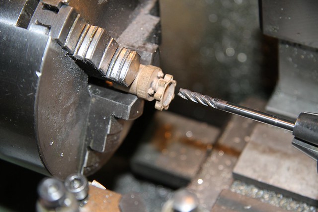 Img_4749 Img_4749 by Robert Shephard, on Flickr A little turning jig was made up to hold the body casting with the 4mm hole fitted to the little turning jig: 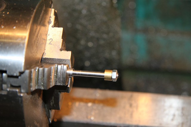 Img_4768 Img_4768 by Robert Shephard, on Flickr  Img_4766 Img_4766 by Robert Shephard, on Flickr The next job was to make a jig to hold the valve body for threading it to fit the boiler bush, which is 1/2” x 26 tpi. This is the jig to hold the body, and note how the tortional load, of threading, is taken…the shaped piece of 1/8” x ¼” steel was shaped with a 3mm endmill and one mounting hole was drilled a close fit on a 4BA hex head screw, and the other mounting hole was drilled with a 0.2mm clearance over the screw thread. This allowed the locating piece to be pushed tight against one of the screw bosses of the body. Ignore the 3 threaded holes that have nothing in them. They were drilled and tapped and then I changed my mind as to how to make it:  Img_4774 Img_4774 by Robert Shephard, on Flickr The body fitted to the jig, ready for cutting the thread:  Img_4769 Img_4769 by Robert Shephard, on Flickr Once the body was threaded, the next job was to turn it around to clean up the surfaces of the valve chamber. Another jig had to be made to hold the body, concentric, in the 4-jaw. This was just a piece of 20mm brass bar with a 1/2” x 26 thread, tapped in it. Thje first 2 threads were then bored out so that the valve body could be screwed in tightly against the underneath surface of the short length of body diameter. The sealing face of the valve body was clocked up to make sure it was close to square to the spindle centreline, and concentric. The surfaces of the valve body, need the absolute minimum metal removed. Probably not more than 3 or 4 thou on each surface max:  Img_4779 Img_4779 by Robert Shephard, on Flickr  Img_4780 Img_4780 by Robert Shephard, on Flickr 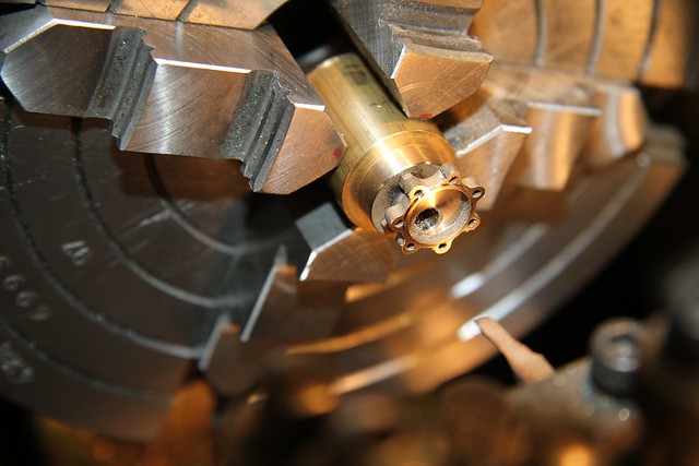 Img_4776 Img_4776 by Robert Shephard, on Flickr The finished valve body:  Img_4778 Img_4778 by Robert Shephard, on Flickr The next job is to clean up the cast cover for the valve. I took a piece of brass bar, and faced off the ends. On one end I drilled and tapped a M4.0 hole in the position shown on Mike’s drawing, for the 4mm dia hole. This helped to position the cover roughly central on the bar. It was locked in place with a M4.0 cap screw. With the casting locked in place on the end of the brass bar, a 1.3mm dia drill was used to spot through 3 of the mounting lugs on the cover. These were then used to drill and tap 3 holes 12BA x 5/16” deep. I found the heads of the 12BA screws were a fraction too large so had to ‘turn’ them down a bit, using a new, flat swiss file, until they just fitted below the central raised sealing surface of the valve cover. Again; the absolute minimum is removed to provide a flat sealing surface for the PTFE valve disc. This face will be further smoothed with 2500 wet n’dry paper, to provide the valve sealing surface. Finally, an endmill was used to relieve the middle of the mounting face, so that the cast, outside boss of the cover, could sit in it, and the cover casting sit down flat:  Img_4790 Img_4790 by Robert Shephard, on Flickr  Img_4792 Img_4792 by Robert Shephard, on Flickr  Img_4799 Img_4799 by Robert Shephard, on Flickr  Img_4802 Img_4802 by Robert Shephard, on Flickr The cover with it’s 2500 grit polished surface:  Img_4803 Img_4803 by Robert Shephard, on Flickr The next operation is to machining the O-ring socket for the valve shaft. The cover, in it’s jig, has to be adjusted in the 4-jaw, to bring the 2.5mm shaft hole, concentric with the lathe spindle centreline. This does need to be as accurate as possible because the O-ring is so small in diameter and section. There is no room for error here, though it is possible to ‘save the day’ if the socket goes too deep….I KNOW(!!) I found it difficult to get the depth exactly right because there was almost no room for measurements. I had to rely on the boring tool cutting perfectly to size….It didn’t!! The O-ring didn’t seal when the stainless steel valve was fitted. The stainless valve was made from a piece of 20mm dia S3126 stainless steel. I picked this spec because it is more rust resistant than S304. It is also easy to machine with HSS tools, which can be made really sharp. The first job was to turn up the main shaft, concentric with the centre of the 20mm bar. If your chuck is not guaranteed dead true, then let the stainless bar protrude from the chuck sufficient to turn the OD for around 25mm as a chucking diameter that is dead true to the valve shaft. The bar was then reversed in the 4-jaw and clocked up again. A 3mm hole was then drilled with a carbide PCB drill, carefully, to ensure the hole was dead centre below the valve shaft at the other end. This hole was then opened up to 1/8” dia with another carbide PCB drill. This produced a dead to size 1/8” hole, as if it had been reamed. This hole could then be used as the location for machining the PTFE valve disc socket. I forgot to take any photos of the actual machining of the valve shaft, but it was a simple turning job. This is the embryo valve fitted to the rotary table for shaping the valve and boring the socket for the PTFE seal disc. The photo is thje start of shaping the curved outline of the valve itself: 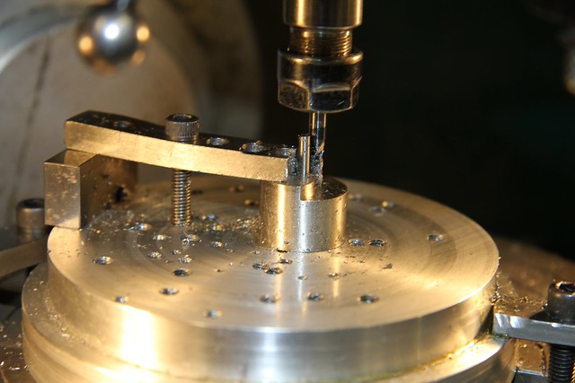 Img_4815 Img_4815 by Robert Shephard, on Flickr This is the valve with the base now roughly shaped, and with the PTFE disc socket bored using a carbide endmill.  Img_4818 Img_4818 by Robert Shephard, on Flickr The next op was to machine the square for fitting the valve handle. Mike’s cast handle only needed the socket lightly swiss filed to get tiny burs out of the square socket. This was then used to check the machining of the square shaft. 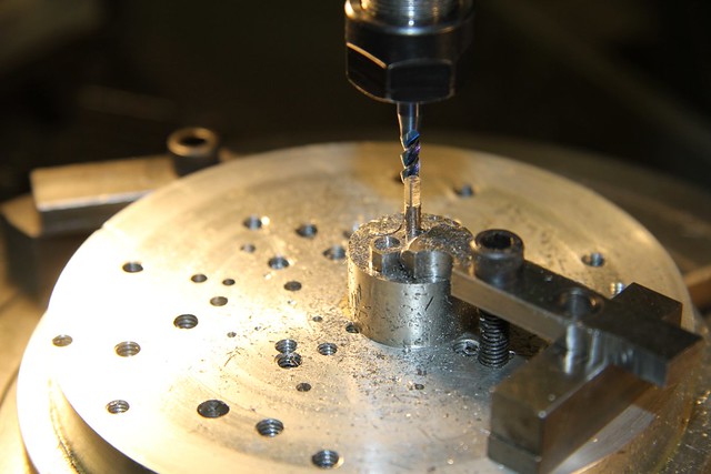 Img_4819 Img_4819 by Robert Shephard, on Flickr  Img_4821 Img_4821 by Robert Shephard, on Flickr The waste material was then cut off the handle casting and ity was tidied up with a fine swiss file. That is all thje work necessary on the handle. The next job was to machine the thread for the handle locking nut, on the end of the valve shaft. The lump of stainless was taken off the mill and put back into the Griptru chuck. For anyone who doesn’t have a chuck they can guarantee is concentric within 0.001” T.I.R., should set it up in the 4-jaw and clock it concentric. There is almost no latiotude for error here because square is almost exactly 2mm and the nut thread is eather 2mm, or as I did, 9BA. I used a 10BA nut and drilled and tapped it 9BA, which worked a treat. The 10BA nut looks scale when compared with my photos of the fullsize.  Img_4823 Img_4823 by Robert Shephard, on Flickr  Img_4828 Img_4828 by Robert Shephard, on Flickr The valve was now parted off, leaving a few thou to clean up after parting off:  Img_4834 Img_4834 by Robert Shephard, on Flickr The finished valve. Note the small diameter at the base of the shaft, for the seal to work on:  Img_4838 Img_4838 by Robert Shephard, on Flickr The shaft was now fitted with the )-ring and assembled into the valve body. The handle was fitted and locked on with the 9BA nut. Oh dear!! It doesn’t seal. Actually easy to get over if you have some brass shimstock of varying thicknesses. I made up some shim washers that would fit into the O-ring socket to make sure they were the right size, and not too big. This is how I made shim washers from 0.004” and 0.008” brass shimstock. I cut pieces of ½” x 1/16” mild steel flat, into pieces about ½” long. I guillotined a strip of 1/2” wide shim and further guillotined it into 1/2” long pieces. These were all then clamped together with the smallest toolmakers clamps, sandwiched between 2 pieces of 1/2” x 1/16” steel. A 2.5mm hole was drilled through the centre of the steel and brass sandwich. A piece of ½” mild steel bar was drilled and tapped M2.5, and a piece of 2.5mm dia steel rod was cut to about 5/8” long. Each end was threaded M2.5. One end was 1/4” long and the other end 1/8” long, and the 1/4”.long end was threaded into the tapped hole in the steel bar, and locked with Loctite. A pair of spacers were turned up to fit the 2.5mm shaft. The steel/brass sandwich was then pushed on and locked with 2 nuts and a spacer each end: 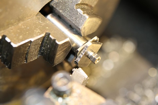 Img_4851 Img_4851 by Robert Shephard, on Flickr  Img_4854 Img_4854 by Robert Shephard, on Flickr The pieced were then carefully turned down until they were 4.4mm O.D., and would fit into the O-ring socket. Different thickness washers were fitted onto the valve shaft BEFORE the O-ring. This made sure that the O-ring would seal between the valve body and the shaft. Another couple odf washers were made up that were drilled 2mm to just fit over the corners of the square. One of these was used either side of the handle to ensure it was held securely. Mi8ke recommends spring washers but I couldn’t get any spring washers anywhere near the size I wanted, so I just made up shim washers of varying thicknesses and used the best one found by trial and error. The valve now seals against me blowing through it, so under boiler pressure, will definitely seal. The finished valve, ready for fitting to the boiler:  Img_4857 Img_4857 by Robert Shephard, on Flickr  Img_4856 Img_4856 by Robert Shephard, on Flickr  Img_4855 Img_4855 by Robert Shephard, on Flickr I forgot to mention…The 12BA hex heads that initially were used to fit the valve cover to the valve body, looked a bit big when compared with the fullsize photo. I found I had some 0.078” A/F hex steel rod, and I made up some 12BA screws, which sit better than the standard screws, and look close to scale.  Img_4858 Img_4858 by Robert Shephard, on Flickr The finish doesn’t look brilliant, but that is because of the high magnification of the photo. I thought the Everlasting Blowdown Valve was finished…….Not quite. I have just remembered, the mounting flange, for the valve, is not round as machined; it is triangular. I will have to make up a jig to hold it at an angle, while it is machined, on each of the 3 sides. I will cover the making and machining, a bit later. Bob |
|