Post by rrmrd66 on May 2, 2020 21:12:49 GMT
Good Evening to you all.
 fullsizeoutput_c1a by Malcolm HARWOOD, on Flickr
The next posting of progress on the 5" gauge Don Young Hunslet build.
Apologies for this being a bit disjointed as I seem to have hit various hold ups and deliveries from suppliers have understandably taken several days longer than normal due to the current crisis.
So let us begin with the steam manifold construction.
This is the bottom half of the manifold constructed from the gun metal cast rod ex Reeves and a piece of standard copper pipe. You may recall I have in the past had doubts about my silver soldering techniques and when i look at this close up shot you can see why. (In my defence I think its recently got a lot better. However still not perfect.)
The two small blocks are the "ears" to be soldered on following by drilling and tapping for pressure off-takes for various items.
One of the problems with the silver soldering of small items onto larger ones and at the same time trying to encourage the capillary flow of the solder ( by gravity) is holding everything still whilst the flux "boils off" and the solder melts. Roger's tip of placing lots of thick flux on the surfaces and allowing it to dry prior to soldering is a good one (The Tippex trick works as well). However in this case I decided to knock up a mini G clamp. This worked well. What didn't work at all well was I must have quenched the assembly too quickly and managed to crack the flange across the screw holes. So back to square one.
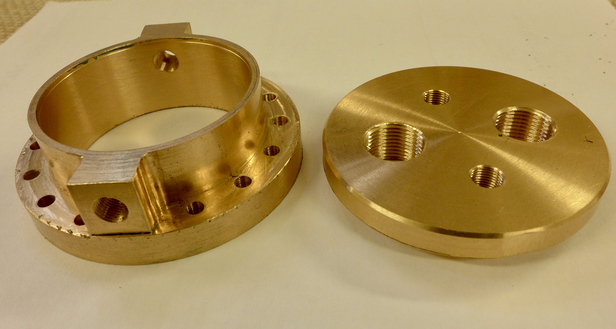
You will recall my moan in my last post about the amount of metal that was left over following the flange being turned up (which you pay for from Reeves as part of the castings set), well there was sufficient metal left over to make the bottom half of the manifold from solid and avoiding the soldering of the "ears" onto the manifold body.
Here is the part finished article. Note that I increased the thickness of the flange in case of the previous trouble. The radius in the corner of the ears went badly awry when I think i tried "down" milling into the corner and the cutter picked up. Hence the markings on the of of the flange. The ears were fished by hand so no real harm done and something not to be repeated in future!
Last post I discussed the removal of the "tongue" on the regulator body as I did not want to drill though fixing holes into the boiler barrel.
I made the plug on top of the regulator thicker that drawing and Loctiteted a 6B stud into it.
A copper disc was then fashioned so that it engaged on the hexagonal plug head. The disc with suitable steam escape holes was in turn clamped to it. This would locate the top of the regulator form sideways movement . A thin walled spacer was inserted between the disc and the underside of the manifold top limiting and tendency to move vertically ( at least upwards.)
Subsequently Andy Higham has come up with a much more elegant locating method in his refurbishment of his Hunslet. I am jealous. Well done Andy.
The disc btw does sit centrally in the bore. It's the old parallax gremlin again in the photograph.
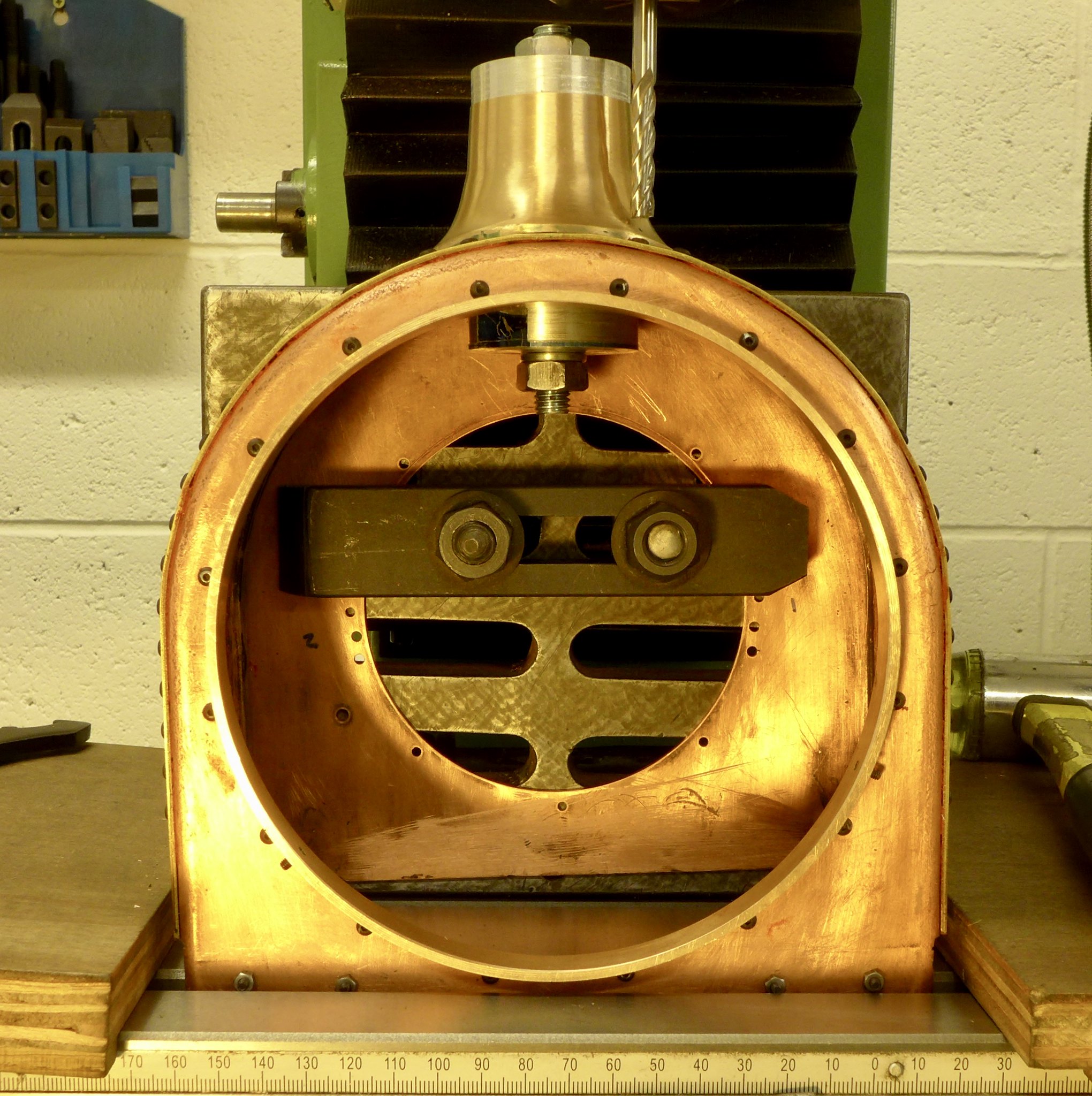
Another wait for something so I next decided to fit the chimney saddle to the smoke box. Here I am cutting a spot face (x4) on the double curvature saddle to enable a 6BA button head screw to fit the saddle to the smokebox passing through to a spacer piece (again wit a double curvature) that will hold the lower portion of he chimney together with its petticoat piece. The chimney is nipped by 2x6BA grub screw in this spacer piece ( hidden for view in this shot) to make sure if doesn't move about. I have a feeling it will make a fine handle that some kind soul may grip one day when I'm not looking. The Alu. discs and M10 stud/nuts are part of the clamping arrangement.
Back to the boiler and the coaxial super heaters.
Shown here are the outer and inner tubes (x2) together with their complimentary plugs.
Next we get to attempting to screw the steam pipe into the regulator body whilst at the same time screwing the other end into the super heater header . This some how seems to contradict the laws of engineering to my mind, but what the heck!
A large "darning needle" was made from 9mm rod and a suitable radius was turned on the end. This was inserted into the boilers steam pipe and placed until it went into the screwed hole in the bottom of the regulator (3/8" dia).
The steam pipe was then slid along it and the screwed portion of the flange at the left had end was screwed into the boss on the boiler, at the same time screwing the other end into the regulator.
Problem is after having done that there is no way of actually tightening up this joint, so a strip down was again necessary and four flats were milled on to the flange. The flange already had 4 stud hole tapped into its face so the trick was to get it tightened up with the 4 holes equispaced and at 12 o'clock.
Eventually success was achieved , but this is a real B****R.
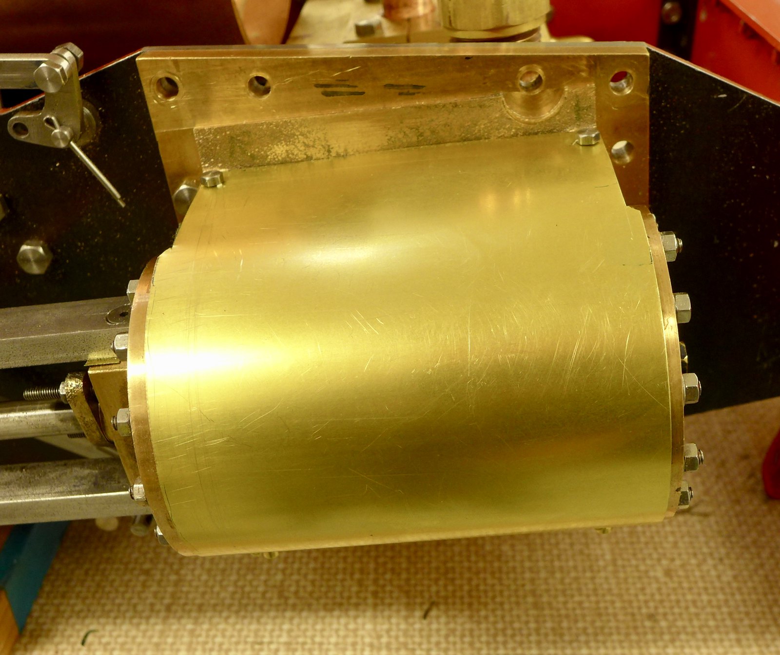
Thinking about the logical order of eventually finishing this locomotive I decide during another lull in the fighting to make the cladding for the cylinders.
Note to anybody about to try and make one of these is to drill and tap the webs of the cylinder casting prior to fitting to the frames and not afterwards.
Drilling 6BA tapping holes hand held in 1/4"thick webs is not to be recommended as the drill does have a tendency to wander!
Therefor behold my horizontal boring machine. Never underestimate the usefulness of that little Dremel drill you bought your beloved for Christmas one year to do the electrics on her dolls house.
Yes, i know the drill is upside down on the drill stand. it's meant to be!
Mission accomplished I am glad to say with no broken drill or taps.
I am still considering whether or not to fit those little triangular spacers to hide the cylinder mounting bolts. Seems a bit unnecessary to me.
Yet another mini diversion.
Someone pointed out that should the engine whilst under steam ever end up on it's side or worse inverted there was little to stop the boiler coming out of the frames. The smokebox end is well tied down but the grate end not so well.
Thus a small retaining plate was made to ensure that once in it's correct longitudinal position the boiler was still free to move horizontally but but vertically.
Finally a few pictures of the connections to the common steam pipe from the super heater header. This is the final shot which I feel will explain the next couple of pictures.
Firstly, note the slight upward angle of the steam pipes into the common manifold. How to get the angles correct for soldering?
This shows how to obtain the the correct alignment by constructing a soldering jig that locates the 1/2"ME union in the common manifold.
Sensible people would make a jig that did both ends at once. I however only has one spare 5/8" BSCY union onto which to mount the manifold
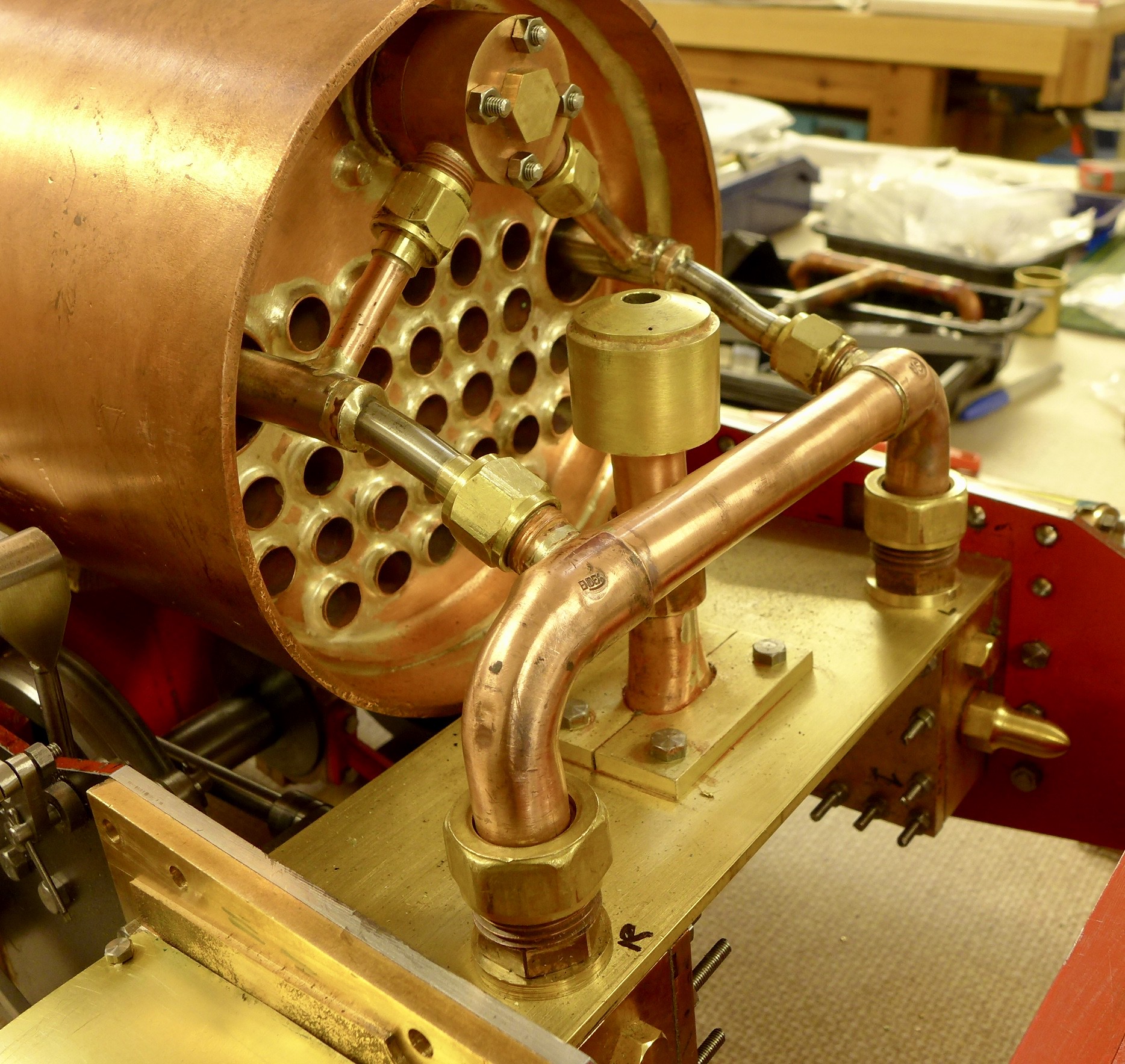
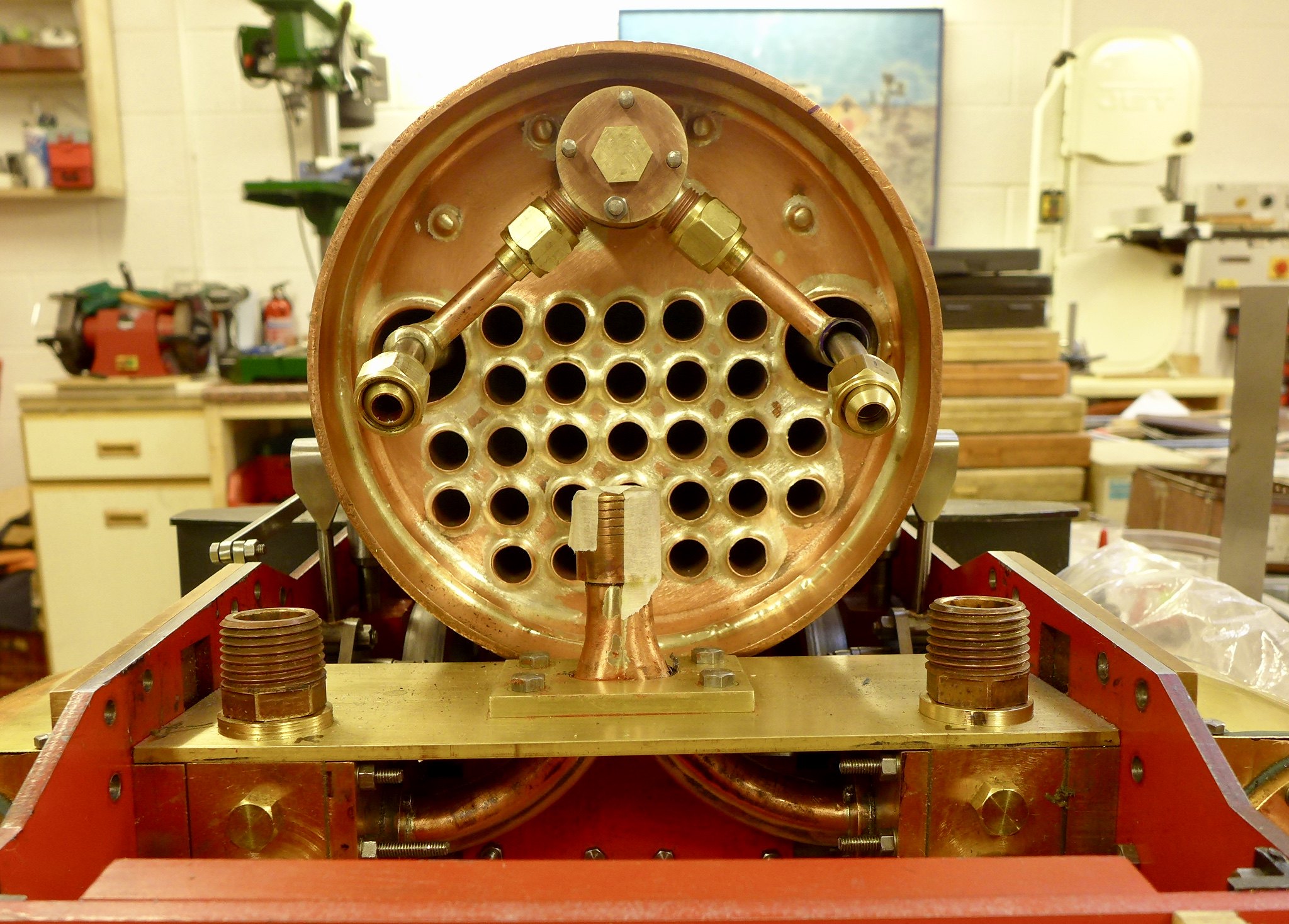
This shows the two coaxial super heater elements joined to the super heater header.
Another note of warning. Don Young suggests that that the angular displacement of the two connecting pipes is 90° (2x45). it is in fact about 96.6°. Both by scaling of the drawing (tut tut) and by dead measuring with rulers and squares etc and a bit of trigonometry.
The first header I made was nearer to 85° plus the header only wanted to tighten up at about 7° past 12 o'clock and you can see that you end up with one pipe much shorter than the other and with a dog leg in it.
I made another and then forgot that in effect it is now "handed" so again it was wrong. However I rescued it by drilling through, turning if round and putting a threaded plug in it.
Eventually we arrive at this last shot where everything appears to be in its correct place.
Nest time I will tell you all about getting it to all mate up with the smoke box and the fight to get your hands and spanner into the smoke box door to finish fitting it.
The blast nozzle is placed just to make sure it all fits and there is room for the steam delivery pipe.
 fullsizeoutput_c1a by Malcolm HARWOOD, on Flickr
Thank you forbearing with me.
Hope you found it of some interest
Regards and stay safe
Malcolm


