|
|
Post by terrier060 on Oct 30, 2020 14:49:30 GMT
I need a lesson on how to solder and cleanup from some of you. I never was very neat at soldering! The marks are where I used soft iron binding wire to hold it all together while soldering. However here is the finished injector body ready for the cones which I am not looking forward to making. I am not sure whether to use the Myford, which is well used and a bit shaky, or whether to use my watchmakers lathe. It is interesting to see how small the injector is compared with the commercial equivalent.  Comparison Comparison by ed cloutman, on Flickr |
|
|
|
Post by Roger on Oct 30, 2020 18:39:54 GMT
Hi Ed,
I think the only thing that matters when it comes to the lathe is whether the tailstock lines up well with the centre line of the chuck. Other than that, I don't think it matters what you use.
|
|
|
|
Post by terrier060 on Oct 31, 2020 12:55:17 GMT
Good thinking Roger. My old Myford has done some hard work and I know it does not line up very well. It's good enough for clocks, but may not be so good for fine work. It is surprising what you find when you have a tidy-up. These were at the bottom of one of my many drawers and are about 50 years old! The taper reamers must be for my LBSC injectors, although I seem to remember a bell-mouthed one which I could not find. The D-bits are for various clacks and pumps (I use end mills now for that job). The odd-shaped file at the bottom - anyone making the Quorn cutter grinder will recognise these. They were to make the spherical parts of the various levers. I turned all mine in free-cutting stainless which has remained nice and bright (see my page 47).  Reamers Reamers by ed cloutman, on Flickr |
|
|
|
Post by terrier060 on Nov 1, 2020 23:26:24 GMT
|
|
|
|
Post by terrier060 on Nov 8, 2020 0:20:49 GMT
The cylinder drain cock levers on the Terriers are quite complicated, being operated from the cab by a lever on top of the LH rear tool box. These were moved on Fenchurch during the A1X conversion, the sanding lever being removed and replaced by steam operated sanding gear. Only the drain cock lever remains and is further forward. The hand lever in the cab is attached to a long flat rod which runs along the underside of the LH running board, along its outer edge. This is accompanied by a similar rod for the sanding gear on the A1 version of Fenchurch. The drain cock levers are further complicated because the actuating lever couples first to the steam chest drain. This drain is lower down than the cylinder drains hence requires a shorter crank. This requires a slotted coupling rod to the front and rear drains. The front and rear drain cocks are coupled by a single axle running across the cylinders. The top diagram shows the positions of the levers when the drains are open, half-way, and closed (from top to bottom). The image at the bottom shows the levers.  Drain Cock Levers GA Drain Cock Levers GA by ed cloutman, on Flickr  Drain cock operating rod Drain cock operating rod by ed cloutman, on Flickr  Stepney 049 Stepney 049 by ed cloutman, on Flickr |
|
|
|
Post by terrier060 on Dec 22, 2020 18:44:07 GMT
Well I recon I must be the only model engineer who can sit on the lav and work on his loco at the same time! With the help of my neighbor Derek and my ME friend Nick, who has the twin of this engine, (but the non-cab version that ran on the quarry terraces, rather than the inclines), we managed to get the engine through the narrow cottage door, and then with the aid of a big lever, wrestled it into the utility room! I made a former and reckoned we had 1/2 inch to spare without hitting the wall. It is amazing how delicately Derek used the lever and we never touched the wall. The cottage has steps so I had to make a temporary wooden floor to take the weight. I suppose taking into account the trolley it must be getting on for 1/2 a ton.  Loco in Utility Room 02 Loco in Utility Room 02 by ed cloutman, on Flickr It was taking too long trying to finish off the loco at the club. Now being shut down and thanks to Nick I have the loco just across the hall from my workshop. I have already made the clacks and am working on the injectors with the help of Roger. (see thread above). The loco was extremely well made by Royston, who really knows what he is about. It has a John Ellis copper boiler and a very well made chassis, so I have my work cut out to keep up the high standard. The paintwork needs to be seen to be believed and I cringe every time I have to drill a hole through it! I imagine Royston looking over me! The loco was all but finished when I bought it, but needed some pipework and other odd bits like a whistle (which I made for one of the Terriers). Having lost Jan, this was the therapy I needed to keep me sane. I wanted something I could run at our track while I was building the Terriers. I will get back to them - I promise. I have had the loco running and it runs extremely well and has passed muster by all the steam enthusiasts at the club, with a nice crisp and even beat (sounds Christmassy!). I need to finish the tender, and fit vacuum brakes, fit a larger whistle - the present one shrieks a bit! Also I could not understand why the two cylinder lubricators stopped working. They seemed OK on the first few runs. Then I saw that they were connected to the valve rods, so when the loco is notched back (and at the moment with a light load it runs fully notched) the stroke was not long enough to operated the mechanical lubricators properly. So I need to make some holes further up the operating levers. I may at some point take the power from one of the valve eccentrics. But that would mean removing the boiler, so that is some way ahead when it (if ever) needs a major overhaul. There are a few uneven bits of track where the loco bounces quite a lot, being an 0-4-0, and one of the springs jumped out of its locating cup. So it may mean lifting the loco with an engine hoist that I have in the shed and fitting slightly longer springs. I may also fit an electric water pump in the tender as an alternative to the injectors. The commercial injectors work OK but are a bit fiddly and don't like working at pressures above 80psi. The working pressure is set at 100psi and the injectors do not like that, so I try and keep it around 80, but it is so free-steaming that by the time it gets to the top our long and steep gradient, all hell brakes loose, even with the door open and the damper shut! So I will take pictures of the progress (if I remember). I am still no further understanding how the Terrier injectors work, so if anyone has any connection with Stepney or Fenchurch at the Bluebell and has taken one apart I should love to hear from them. |
|
|
|
Post by terrier060 on Dec 23, 2020 15:47:17 GMT
Just setting up the Tormach to cut out the collar for the drain cock pipes. On the North Wales Hunslets the pipes varied. Some had none, some short stubby ones, and others long ones.  Drain cock collar Drain cock collar by ed cloutman, on Flickr Now have to decide where to cut off the pipes. |
|
|
|
Post by terrier060 on Dec 26, 2020 16:56:45 GMT
Drain cock pipes are now fitted. I decided to keep them short of the buffer beam, as many of the photos I looked at either had no pipes, or short ones. So I have made these long enough to blow the steam cleanly past the buffer beam. The collar is hard-soldered to the pipes and makes quite a rigid setup.  Mwfanwy with drain cock pipes fitted Mwfanwy with drain cock pipes fitted by ed cloutman, on Flickr I bought a cheap vacuum gauge; I think it was about £7. I saw no reason to pay £50 for a brass-covered one! Why not make my own cover to fit? Just a bit of nice easy machining on the lathe.  Vacuum Gauge in situ Vacuum Gauge in situ by ed cloutman, on Flickr. Please, if anyone has a plan of the operating vacuum brake lever I should appreciate it very much. There is a graduated version that I would prefer. Julian said there was a series by Brian Hughes in ME, but unfortunately I do not have copies of that year. |
|
|
|
Post by steamer5 on Dec 26, 2020 18:57:58 GMT
Hi Ed,
Nice work on the vacuum gauge, must remember that idea.
On the cylinder drains, a small suggestion if I may, having them point forward is great, you can see them working, the only issue is if the discharge along the rail! You soon find that you start to have traction issues & the others drivers get grumpy! Have seen were a 5” loco discharge pointed out nicely only to hit the 7 1/4” rail!.
Cheers Kerrin
|
|
|
|
Post by terrier060 on Dec 26, 2020 23:06:12 GMT
Cheers Kerrin - I will keep an eye on that. In fact they are well outside the rails as the wheels are between the frames. They also are elevated like the cylinders, but it is a good point. We do not have trouble with it's twin Hunslet, which has the pipes running through the buffer beam so should be OK. Yes the gauge cover worked well except that the cover glass is the plastic one it came with.
|
|
|
|
Post by David on Dec 27, 2020 3:07:27 GMT
The gauge looks great - excellent idea.
|
|
|
|
Post by terrier060 on Dec 27, 2020 11:06:55 GMT
Thanks David. Today I am going to cut out a special spanner to tighten the lock nuts on the drain cocks. It has to be very slim. The Tormach is very good for these tedious jobs. On the list are a box spanner for the blowdown and several other special tools. You know how it is looking for a spanner when you are running at the track. The one you want is always at the bottom of the pile and it takes an age to get the correct one. Well it does if you are as badly organised as I am. I know some of you have a really good organised toolbox!  Drain cock lock nut spanner Drain cock lock nut spanner by ed cloutman, on Flickr Drain cock lock nut spanner by ed cloutman, on Flickr |
|
|
|
Post by terrier060 on Dec 30, 2020 1:41:54 GMT
It's mostly bits I am making now to finish off the engine. The LH and RH injectors needed pipes fitting to their overflows, because it was not possible to see the ends of the pipes while driving, and I am too deaf to hear the chirping noises when they have picked up properly! I have turned the ends down so that they do not blow sideways and scald passers-by. You can just see them beneath the running boards. They actually are quite long as they bend 90 degrees and travel the width of the running boards before bending another 90 degrees. 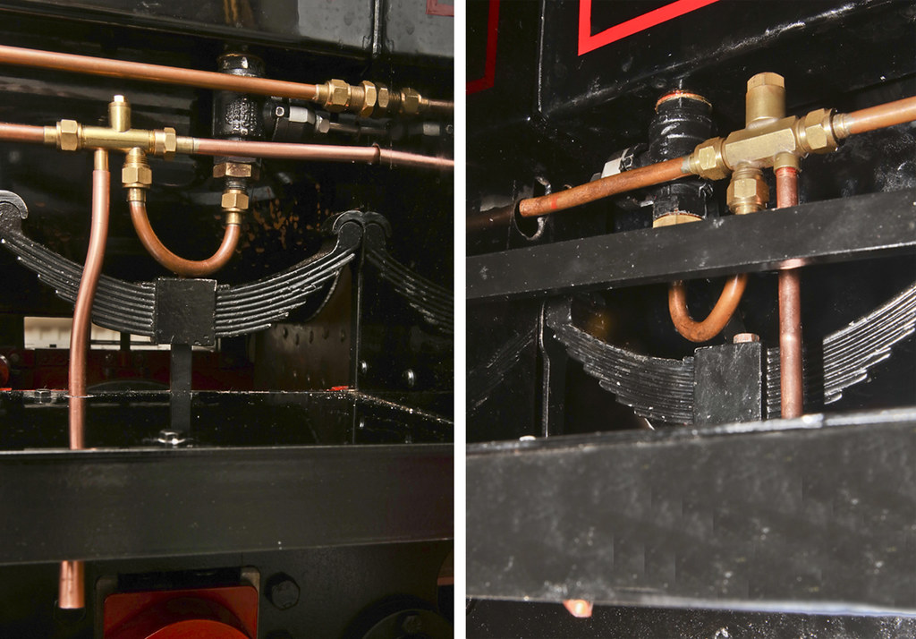 LH & RH Injectors with overflow LH & RH Injectors with overflow by ed cloutman, on Flickr I made some stainless 2BA nuts, as I did not have any in stock and I needed a couple. It is easy to set up and machine on the Tormach just by centring a 1/2 inch diameter bar and then after machining the hexagon, drilling and tapping in the lathe, putting on the chamfer and then parting off. Final operation is to mount in a three-jaw and chamfer the other end. The nuts lock the levers to the valves that control the water to the injectors.  2BA stainless nut manufacture 2BA stainless nut manufacture by ed cloutman, on Flickr The final pieces that I have made are the stanchions to steady the water valve levers. I could not attach them to the boiler lagging as I had no way of telling how strong the lagging was, so decided to make them stand-alone. I used stainless, but did not have the right flux. After a couple of attemps I did manage to solder them using Easyflo or something similar that I had on the shelf. I still have a few rods of the old cadmium-based solder and I cannot believe the difference in the way it flows compared with the modern stuff. The other job was to make the drain pipes to the water gauges. These had to be short enough to miss the rear firebox damper. Otherwise it was fairly simple pipework, with the ends curved away from the rear axle and valve eccentrics. Just a final comment. Though working in 7.25 inch gauge, I notice that my stanchions and levers look a little 'light'. I think I am so used to working in standard gauge with 'Terriers', that I find it hard to adjust to narrow gauge, and particularly 4 inch scale which produces a even large locomotive. I will have to work on that one!! Happy New Year to you all, and let's hope 2021 is and improvement on last year!  Cab with stanchions Cab with stanchions by ed cloutman, on Flickr |
|
|
|
Post by terrier060 on Jan 3, 2021 18:07:04 GMT
A really fiddly job today. Probably easy with the boiler and smokebox off, but with big shaky hands the air was blue at times! Basically I had to remove the rocking levers and drill and tap a couple of holes in each so that I could increase the stroke when the loco is notched back. The lubricators were delivering oil when in full gear but the clutches were not working when the lever movement was small. This is the disadvantage of taking the power from the valve rod.  Cylinder lubricators Cylinder lubricators by ed cloutman, on Flickr |
|
|
|
Post by terrier060 on Jan 4, 2021 22:36:56 GMT
just maybe it is not such a bad idea. It introduces more oil into the cylinders when the engine is working hard! Would be nice to have a sight feed.
|
|
|
|
Post by terrier060 on Jan 8, 2021 18:17:02 GMT
I am going to make a start on the injector cones now, though I hardly dare after the very detailed and skillful thread by Roger! Mine are conventional though, and Roger and Bob Bramson helped me with the initial design (see previous page of my thread). It requires making a very fine parting tool so I first have to modify my Quorn cutter grinder which I have been meaning to do since 1985. I have made a new mandrel to accommodate C3 type collets, which I believe were used in the Boxford lathe. They are very neat. I also need a mandrel with a square hole through the middle to take tool steel. Not so easy to make unless you have a large broach. Probably easier to make it in two halves and solder it together. The Quorn, which is a mark 1 version, looks very dated now, but I still love all the round-ended knobs and fine scales. I remember getting a phone call or stopping to have tea with a friend and messing up one of the scales, but I can't find the error now so it can be a test for an observant model engineer who comes to own it after I am gone!  C3 collet and holder in Quorn C3 collet and holder in Quorn by ed cloutman, on Flickr |
|
|
|
Post by terrier060 on Jan 9, 2021 10:20:41 GMT
This is the one fitted to Fenchurch - as you say it could be a later model, but it is all I have to go on so I will try and make one to this model. May have the same problems as Roger though, when departing for the standard model design.  Injector 01 Injector 01 by ed cloutman, on Flickr |
|
|
|
Post by terrier060 on Jan 10, 2021 16:25:54 GMT
OK you have got me going now. I fancy having a go at making one of these injectors in miniature, because they are so neat. I expect Roger will think me crazy, but like Roger I like to try something new unless of course one of you knows whether it has been tried before. The basic design is so neat and gets rid of the ball and chamber so that you have the very tidy arrangement as in the photos of Fenchurch above. OK it may be a pipe-dream, but seeing as several of you are having a go at innovative designs it seems a good idea to try another one. I must admit that if you can get the one-piece cone to work it does simplify the making of injectors, but it would be difficult to make a scale one look right on a Terrier because of the ball chamber. Dave, I hope you don't mind because I have used your photo. If you object I will remove it immediately.  Terrier Injector Plan Terrier Injector Plan by ed cloutman, on Flickr The basic operation is ingenious, because Roger and I had to scratch our heads to see where the overflow water went as the injector started. Then I looked closely and spotted the spiral vanes which we equate to the blades on a lawnmower cylinder. This will allow water to pass as well as spinning the mixing cone as it shuts. The basic operation is that in the cone's present position it allows water to pass from the tank or tender freely through the overflow. As the steam is turned on and the injector picks up, the mixing cone moves to the left (or vertically when on the Terrier) and the valve seats, shutting off the water flow from the tank, but still allowing passage through the spiral flutes until there is a full flow out of the delivery. Scaled down to 7.25 inch gauge it looks like the drawing underneath, but I am surprised at how large the bores in the cones are, and I expect a lot of experimentation will be required. Now those of you with technical knowhow my say that this cannot possibly work in miniature, in which case it is a non-starter. But it may just be worth a try. |
|
|
|
Post by Roger on Jan 10, 2021 17:13:20 GMT
Hi Ed,
This is a really interesting design, and I think it could be made to work in miniature. It's quite a challenge to design it such that it's possible to keep concentric in a body. My guess is that the floating cone wouldn't need to be an especially close fit, and it could even possible be made from Fluorosint which might resist scale attaching to it. I'd be very interested to see a miniature design for this type fleshed out into something practical.
|
|
|
|
Post by terrier060 on Jan 10, 2021 18:32:44 GMT
Thanks Roger. I will give it a go. First I will make the cones for the previous design that you and Bob helped me with. I have got the Quorn going and have just made the 30 thou parting tool that I require for splitting the combining cone. Apologies for the state of the grindstone, but I have to take the machine in the garden to dress the stone as I don't like the stuff going all over the workshop, and it is dark and cold outside! I have already ground the 1 degree taper on the sides of the tool and am set up for grinding the 3 degree clearance on the end of the tool. What I have already found is that my eyesight is terrible compared with when I last used it some 30 years ago. I find it very difficult to see the scales and need an eyeglass. The rotary table scale is very clumsy as the detent is in a bad position. In fact it really could do with two registers at 90 degrees to each other.  Grinding 3 deg front rake on parting tool Grinding 3 deg front rake on parting tool by ed cloutman, on Flickr |
|


