Hi All - I have decided to have a go at making my own injectors during this lockdown in Wales. It is considered a bit of a 'black art' by my fellow model engineers at the club. I have had a lot of help from Roger Froud and his thread, and the author Bob Bramson who designed these injectors. Bob is a fine model engineer, as well as a professional one, and I am really glad I have met him (not yet in person, but one lives in hope that this dreadful virus will eventually be conquered). Roger, most of you know is just amazing and got me hooked on CNC but unfortunately not to his standard. He, like me, likes a challenge and to try something new. I still have not got a 3D printing machine, but I suspect I shall give in eventually!
It will be a 26oz injector to conventional design, with a working pressure of 100psi. If I can get one to work, I shall then try to make smaller ones for my A1X version of the Terrier, which has a neat design as you can see from the photo (yes a genuine photo taken on film)!
If anyone has a drawing of the inside of one of these vertical Terrier injectors I would be eternally grateful.
 A1X injector
 by
ed cloutman, on Flickr
The present design is made to fit existing pipework on my Hunslet, which I have accomplished by lengthening the ends of the cones, but not the critical measurements. It was also important that the steam and water connections were in exactly the same place to fit the existing pipework. I am making the body parts a press fit before soldering, though I may change to Derek Brown's method of using a jig, when I make the second one. The cones are designed with help and discussions with both Roger and Bob. Roger convinced me that End Regulation was the way to go, and I must admit I like the design of a stubby steam cone rather than the fine exit cones that are fitted to commercial injectors. Bob then kindly looked at my drawings and revised them for me. Any deviation from his design are entirely my own and I take full responsibility for them.
I have made injectors before, to LBSC design, and they have been reliable, but usually required adjustment of the water feed to get them working sweetly. Also they were designed to work at lower pressures. This was many, many years ago when I was a member of the Soton Society at Cobden Meadows (1960s).
Bob explains in his book the principals of how injectors operate, and although much of it is above my head, it does help in the understanding of these 'magical' pieces of engineering, with no moving parts, that can take steam at boiler pressure and pump water into the same boiler! Also I like a challenge and hope that this machining is not out of my comfort range, being more like watch-making that model engineering!
The basic dimensions are shown below and as Bob has said to me, final adjustments of the steam cone come with experimentation to find the sweet spot. I like the design which is very small and neat for quite a large delivery. Roger is making the taper reamers for me so I know they will be excellent. Also that is the hardest part, and something I could not do in HSS. Mine were made in silver steel and hardened.
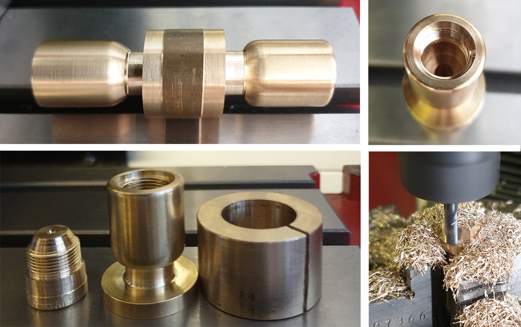
The body shown below is part-made. The ball chamber is soldered, but the overflow and water entry have yet to be soldered on.
 part made body
 by
ed cloutman, on Flickr
The method of designing the cones is taken from Roger's thread which you can follow to get a more thorough understanding. It is his thread that got me really interested after reading Bob's book. Well worth a read.
The notes below are my interpretation of Bob's book and the help Roger and Bob gave me. So if there is any disagreement it is purely my fault. It does help to explain how I produced the drawings, but we shall have to wait and see what results it produces in practise.
Critical measurements of the design:
Steam cone diameter = 0.048" (taken from graph in Fig 20 in the book) - No.56 drill
Combining cone diameter = 0.043" (taken from graph)
Delivery cone diameter = 0.033" (taken from graph) - No. 66 drill
Exit diameter of condensing cone = 0.076" (explained in text note 1) - No.48 drill
Gap between steam cone and combining cone = 0.005" (adjusted when testing - see note 2)
Gap between condensing cone and mixing cone = 0.040" (explained in text note 3)
Gap between combining cone and delivery cone = 0.064" (determined using CAD)
Taper angle of steam and combining cones = 9 degrees (given)
Taper angle of delivery cone = 6 degrees (given)
Length of mixing cone = 0.170" (determined using CAD - see text note4)
Length of condensing cone = 0.150" (explained in text note 4)
Length of delivery cone = 0.450" to 0.550" (explained in text note 5)
Length of steam cone = 0.175" (determined using CAD - see text note 6)
Explanation of notes:
1. The main consideration here is that the ratio D/d should not be below 1.35 or there is a complete failure to raise a vacuum in the ejector part of the injector. A ratio of between 1.38 and 1.45 is suggested, although ratios larger than this are acceptable. Bob amendment my drawing with a diameter of 0.076" which gives a D/d ratio of 1.58.
2. This gap needs to be refined by experiment, but 0.004" is shown as a starting gap in Fig 24 of his book for this size of injector. This can be adjusted as required using a test rig or on the model to find the sweet spot.
3. A gap of at least 0.040" for an injector of this size.
4. Bob does state that with injectors working at pressures over 90psi and greater flow rates, the length of the mixing cone should be longer than the condensing cone. The lengths of the condensing and mixing cones are given in table 4 of the book as 0.150" and 0.185" respectively for an injector of this size, but these are a guide and should not be regarded as exact dimensions.
5. Other than the throat, the taper angle and length of the delivery cone are not critical, but Bob usually makes the taper 6 degrees and the length between 0.450" and 0.550"( pers comm).
6. Bob has determined that the exit diameter of the steam cone should be about the same diameter as the exit diameter of the condensing cone. Thus the length of the steam cone is determined by drawing a 9 degree taper in CAD from the throat of the steam cone to an exit diameter of 0.075". This gives the steam cone a length of 0.172". He also states that a parallel hole can be used from the entrance of the steam cone to just before the throat without affecting performance.
Injector Cone General Arrangement
 LH Injector GA
 by
ed cloutman, on Flickr
Cone Dimensions
Top to bottom - steam cone, combining cone, delivery cone
 RH Cone dimensions
 by
ed cloutman, on Flickr
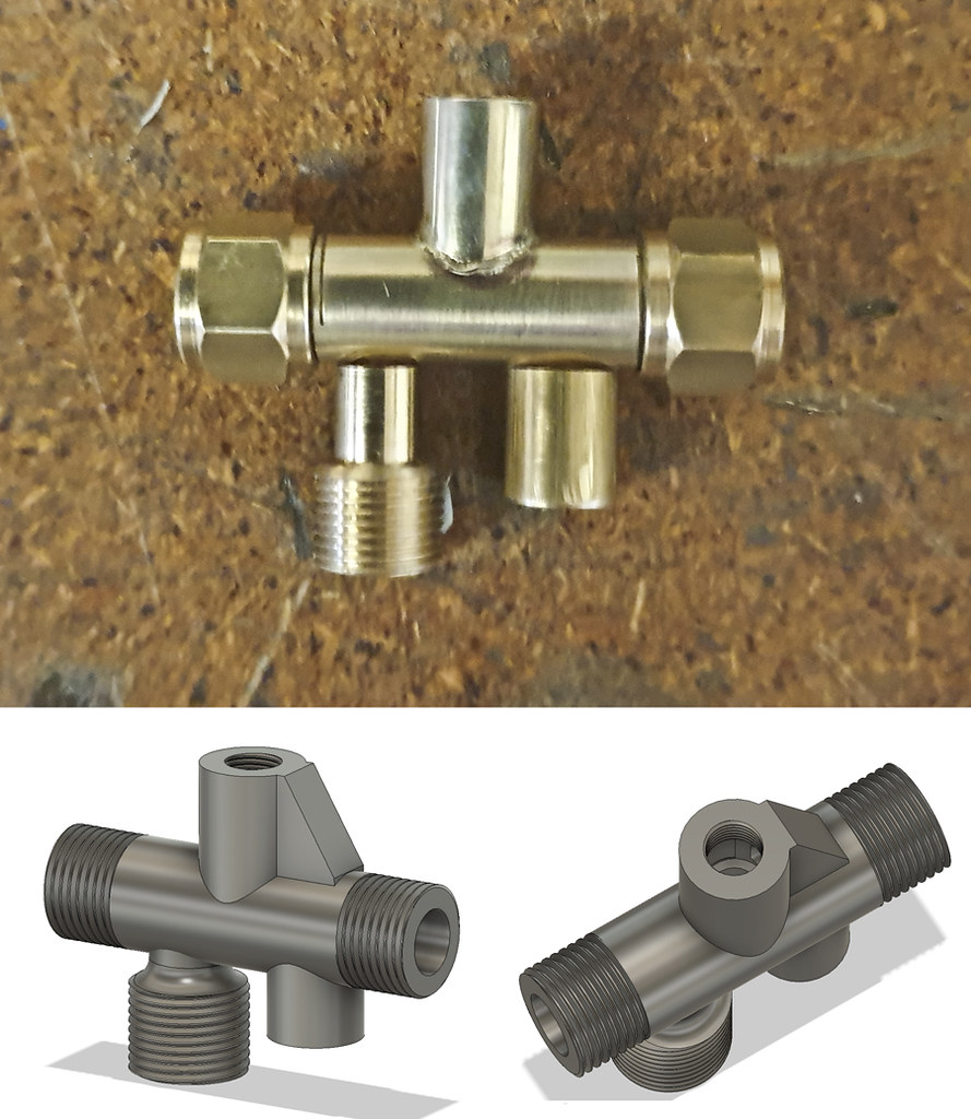
Injector bodies - these were made to fit existing pipework
 RH Bodies
 by
ed cloutman, on Flickr