|
|
Post by terrier060 on Jun 5, 2022 21:03:49 GMT
I sorted the G-code and with fingers crossed loaded it into the machine. Then I went away out of earshot and got on with judging some prints. All went well. I set up the workpiece upside-down and machined the bottom first. If I had machined the top first I would have machined away my origin and would not have been able to perform the second setup. The bottom has a step in it so that when viewed attached to the valance angle, it appears to be the same thickness as the angle (about 40 thou). The workpiece is then set up facing upwards and the recess machined for the angle. This will be fixed with two very small rivets and soft-soldered. After soldering, the end piece and rivets will be machined and polished flush before painting. Only seven more to go, four being mirror images.  End of valance End of valance by ed cloutman, on Flickr |
|
|
|
Post by terrier060 on Jun 10, 2022 13:40:00 GMT
Finished machining all the ends and the first is riveted and soft-soldered in place. Only seven more to go! Then I think I will glue the valance to the running board, held by a few very small rivets. Stroudley used flush riveting, which looks very tidy but makes modelling more difficult as the rivets have to be hidden as in clock work. And I hate soldering with the unpleasant smell and mess of the flux.  Valance ends Valance ends by ed cloutman, on Flickr |
|
|
|
Post by coniston on Jun 10, 2022 20:28:53 GMT
Nice neat job there Ed.
Chris
|
|
|
|
Post by terrier060 on Jun 11, 2022 23:43:09 GMT
Thank you Chris. It's the thought of doing the lining that is worrying me. There is not much room for the lines on either the A1 or A1X versions!
|
|
|
|
Post by terrier060 on Jun 24, 2022 21:01:40 GMT
The A1X running boards are now in place and it looks more like a loco. I can now fit the splashers and the cab. Then the reversing lever which is very elegant but is part of the cab. The vallances are attached to the buffer beams with very small allen grub screws.  Running Boards S Running Boards S by ed cloutman, on Flickr |
|
|
|
Post by terrier060 on Jun 30, 2022 23:01:40 GMT
After keeping clear of it for nearly three years I have got the dreaded Covid so I am spending my time designing the splashers and side tanks for the Terriers, using the full size drawings. The Terriers have a lagging sheet on the outside of the tanks, which was there when they were using the condensing apparatus. They were not required for the later engines as they were fitted with injectors rather than crosshead pumps. It could be useful on the models, as I could use a thin outer skin of. steel covering the internal brass tank. The lagging means that the top of the tank has a 1/16in recess, useful for storing irons etc. It also has the handrail stancheons fitted to it housing the hollow handrails through which the blower and lubricator are controlled from the cab. Very neat and clever. Stroudley was a brilliant engineer, just a pity the looks of the engine were spoilt somewhat when the ugly pipe was attached for the later braking system. I am sure with a bit of thought and care this could have been avoided.
Pictures to follow.
|
|
|
|
Post by terrier060 on Jul 4, 2022 9:53:13 GMT
I have spent quite a lot of time preparing these drawings. I should be able to machine most of them on the Tormach. I am not sure yet how to go about bending the sheets as I am using 2mm brass.  Side Tanks Side Tanks by ed cloutman, on Flickr |
|
|
|
Post by terrier060 on Jan 15, 2023 16:44:04 GMT
Ordered some of the brass for the side tanks at last. There are slight difference between the A1 and A1X versions
|
|
|
|
Post by terrier060 on Apr 24, 2023 1:03:49 GMT
Bruce from Oz has been asking me about the Terrier roof so I had a look at what I had done on my Pages 32 and 33. George quite rightly reminded me that the roof was made in two parts, which I see I had shown on the drawing. I appear to have had a bug at the time and was not thinking straight!
My idea is to make the roof in two halves, though the frame which includes the gutter will remain at the front and sides to stiffen the cab sides. The strip will be soldered to the front half, inside and out, leaving a groove for the rear of the cab roof to slide into. The rear spectacle plate will be attached to this, the base of which will be located in the top of the coal bunker. I have not finalised the design or drawn it out yet. I will do some thinking and sketches.
This will make driving the loco possible and still keep some resemblance of the roof present.
|
|
|
|
Post by terrier060 on Nov 9, 2023 23:39:50 GMT
Thought I would have a go at CNC machining the cab beading. I am going to use mild steel as it is not painted on Fenchurch. I have the measurements from the full size drawings. It is a T-section riveted to the inside of the cab. I am machining it in three stages, and fixing it to a dowelled jig to ensure correct location when I turn it over to machine the other side, as recommended by Roger. 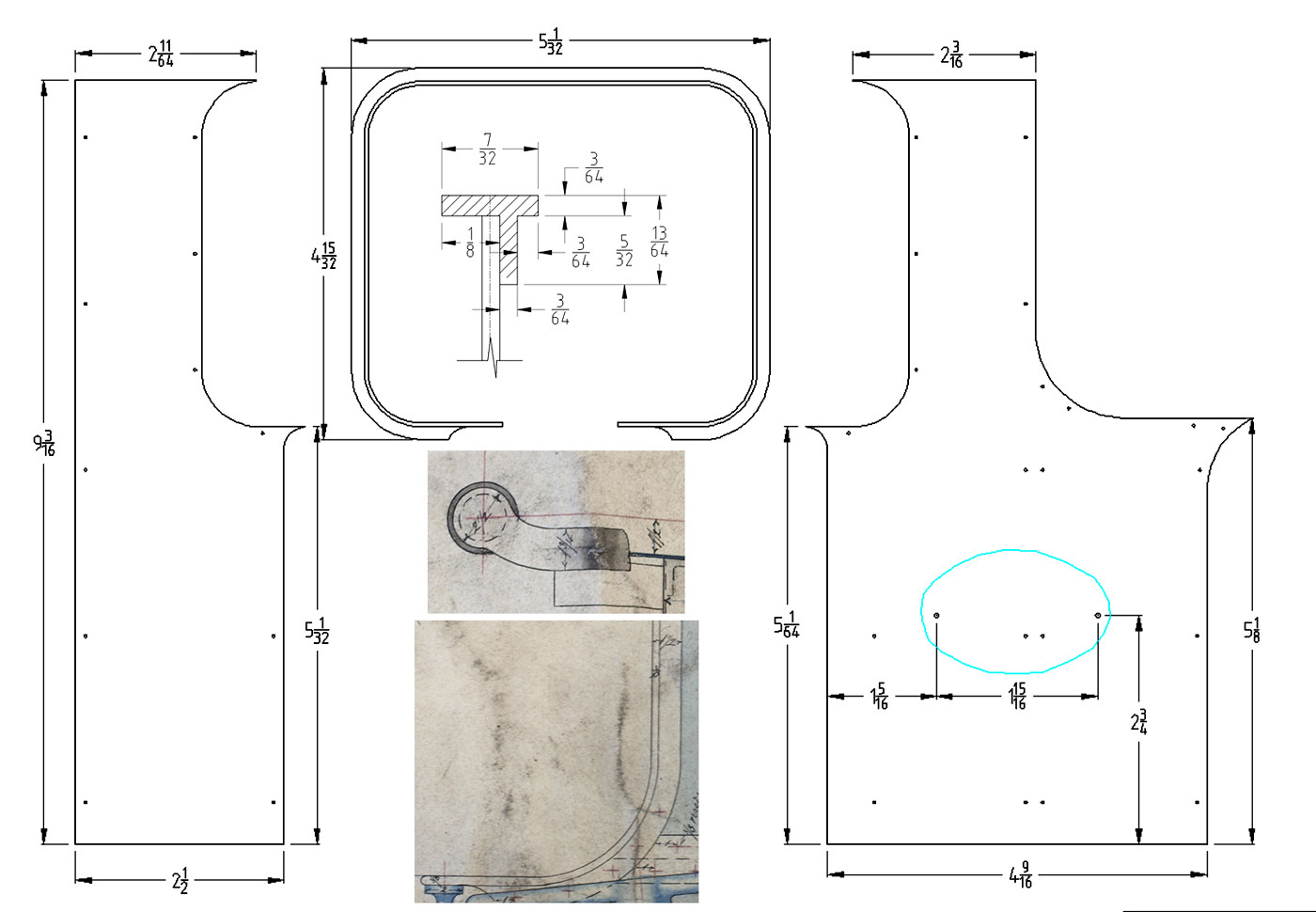 Beading detail Beading detail by ed cloutman, on Flickr |
|
|
|
Post by terrier060 on Nov 10, 2023 0:00:30 GMT
Stage 1 forms the outside of the beading and allows for the thickness of the cab side. Stage 2 cuts the inside, and stage 3 profiles the outside. The lower part of the handrail is extended to allow it to be bent to fit the stancheons.  CNC process for all beading CNC process for all beading by ed cloutman, on Flickr |
|
|
|
Post by terrier060 on Nov 29, 2023 1:47:13 GMT
I machined the first piece of beading for the cab handrail. I did wonder whether it was worth all the trouble, but was surprised at how accurately the beading fitted the cab sides. They are not yet riveted, but fit exactly. I was very pleased at the accuracy of the Tormach. There is no doubt that CNC is the way to go, though it may take longer than more traditional methods. I first made the jig with the two pins to register the work accurately. I machined the jig and the work sheets individually rather than using the jig to drill through, as the machine is so accurate that they all registered perfectly. The pins were glued using Permabond. The base plate was clamped to the bed of the Tormach and centred on the centre-pop. It will remain there until all eight beadings are machined. There is only one change of tooling required, as the two sides are cut with an 8mm end mill and finally cut out with a 4mm end mill. By machining this 'I' section in mild steel and riveting it to the cab sides, it makes the cab very rigid, as I have used 36 thou brass for the sides to keep as near scale as possible. With hindsight I wish I had used steel, but brass does have the advantage of being able to soft solder it together. I am using very thin brass angle for the corner and roof joints and there are four boxes in each corner of the cab, so it should give ample support for the brass. 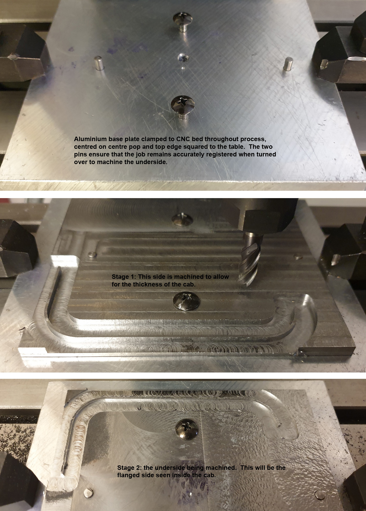 Machining beading Machining beading by ed cloutman, on Flickr  04 Cab beading 04 Cab beading by ed cloutman, on Flickr |
|
|
|
Post by terrier060 on Dec 5, 2023 14:42:09 GMT
This is the final Stage 3 for the remaining cab sides on Loco No 1. The Cab beading has been machined to depth on both sides and this final stage has contoured around the beading leaving tags to stop the pieces falling out. I now need to saw through the tags and clean up before riveting them on to the cab sides.  Stage 03 Stage 03 by ed cloutman, on Flickr |
|
|
|
Post by Roger on Dec 7, 2023 17:40:47 GMT
Excellent! That's a great way to do it.
|
|
|
|
Post by terrier060 on Dec 9, 2023 23:01:01 GMT
Thanks Roger. Yes it has worked better than I thought. Pity I couldn't have made it in freecutting stainless, but you seem to only be able to get it in rod or hexagon in the UK.
The cutters have arrived from China so we shall se how good they are. I managed to use a single 2mm cutter for all four final cuts, but the 6mm cutters will only just about do 2 of the first stage.
I have had some very bad news which has shocked me a bit. My friend Brian with the steam launch has died. We have been working together on that boat for about 5 years, and put a new boiler in it. We have had many nice trips up the Taff and Ely Rivers and up to the Norwegian Church. He is a great loss to South Wales Historical Societies, as his knowledge of industrial archaeology in the Valleys was second to non. He had also just received a substantial grant to put a compressor in the Hetty winding house, which I believe is the only engine left that could run on steam still if they had a boiler. I hope someone can still carry on the project, but he had made it his life since retirement as well as giving many lectures.
|
|
|
|
Post by Roger on Dec 11, 2023 16:44:28 GMT
Thanks Roger. Yes it has worked better than I thought. Pity I couldn't have made it in freecutting stainless, but you seem to only be able to get it in rod or hexagon in the UK. The cutters have arrived from China so we shall se how good they are. I managed to use a single 2mm cutter for all four final cuts, but the 6mm cutters will only just about do 2 of the first stage. I have had some very bad news which has shocked me a bit. My friend Brian with the steam launch has died. We have been working together on that boat for about 5 years, and put a new boiler in it. We have had many nice trips up the Taff and Ely Rivers and up to the Norwegian Church. He is a great loss to South Wales Historical Societies, as his knowledge of industrial archaeology in the Valleys was second to non. He had also just received a substantial grant to put a compressor in the Hetty winding house, which I believe is the only engine left that could run on steam still if they had a boiler. I hope someone can still carry on the project, but he had made it his life since retirement as well as giving many lectures. That's such a shame, I was looking forward to meeting him and seeing his Steam Boat. Sadly, nothing stays the same for long. You have to make the most of every day, you never know what's coming around the corner. |
|
|
|
Post by terrier060 on Dec 11, 2023 22:17:20 GMT
How true! I checked and we worked together on the boat for over eight years. I have known him much longer as he asked me to overhaul the three clocks in Pontypridd Museum where he was the curator. He was so into the industrial revolution, that he had two longcases by local makers side by side, one on local time and the other on mean time to show people how confusing it became with the coming of the railways.
|
|
jma1009
Elder Statesman

Posts: 5,901
|
Post by jma1009 on Dec 12, 2023 0:43:52 GMT
I’m sorry to hear about Brian.
Our paths must have crossed as I was a regular visitor to the excellent Pontypridd Museum pre Covid for by 2019 some 18 or 19 years.
|
|
|
|
Post by terrier060 on Mar 14, 2024 22:25:24 GMT
Hi Roger
If you look at my page 33 you will see the shape of the Terrier roof which is domed to stop drumming. I intend to make it in two halves, the rear part removable to facilitate driving, the join behing hidden by the convenient strap which runs across the roof.
If I 3D printed a male and female die and annealed the brass sheet which is 38 thou thick, would it be strong enough to press out the roof section? The die would have to be made of solid plastic.
Ed
|
|
|
|
Post by Roger on Mar 23, 2024 11:35:57 GMT
Hi Roger If you look at my page 33 you will see the shape of the Terrier roof which is domed to stop drumming. I intend to make it in two halves, the rear part removable to facilitate driving, the join behing hidden by the convenient strap which runs across the roof. If I 3D printed a male and female die and annealed the brass sheet which is 38 thou thick, would it be strong enough to press out the roof section? The die would have to be made of solid plastic. Ed Hi Ed, Sorry for the late reply, I haven't been on the site for ages. It's hard to know if a 3D printed former would work, but it's definitely worth a try. I'd use PLA, and 100% infill so it's solid. PLA is pretty rigid, so that's probably as good a material as any. You'll want to make the former as small as possible, else it's going to use a lot of filament. |
|


