|
|
Post by RGR 60130 on Feb 1, 2019 12:28:22 GMT
And that's despite going to Spec Savers 😄
|
|
|
|
Post by Jim on Feb 1, 2019 19:05:35 GMT
You're not alone Reg. I'm seeking a refund on my specs.
|
|
|
|
Post by runner42 on Feb 2, 2019 5:22:31 GMT
Brian, Looking at the photo of radius rods they appear to be identical. Does the design not require a handed pair? Hopefully I'm missing something. Regarding the cylinder pattern, it should be fine for cast iron or gunmetal. The difference in shrinkage will be neglegible. Reg Hi Reg, what you see is two photos of the same radius rod. My Error was after cropping and splicing the photos I picked the best two for clarity, my camera has the habit of producing out of focus pictures and these happen to be two sides of the same radius rod. Having deleted the other photos I can't correct my error until I have chance to take another photo of the other one. Brian |
|
|
|
Post by runner42 on Feb 4, 2019 5:52:38 GMT
|
|
|
|
Post by runner42 on Feb 7, 2019 7:30:32 GMT
Once again I am foxed by DY's drawings. The crosshead doesn't appear to be able to accommodate the connecting rod. Any ideas on how the two items are connected together? Also how deep is the hole for the piston rod? Brian 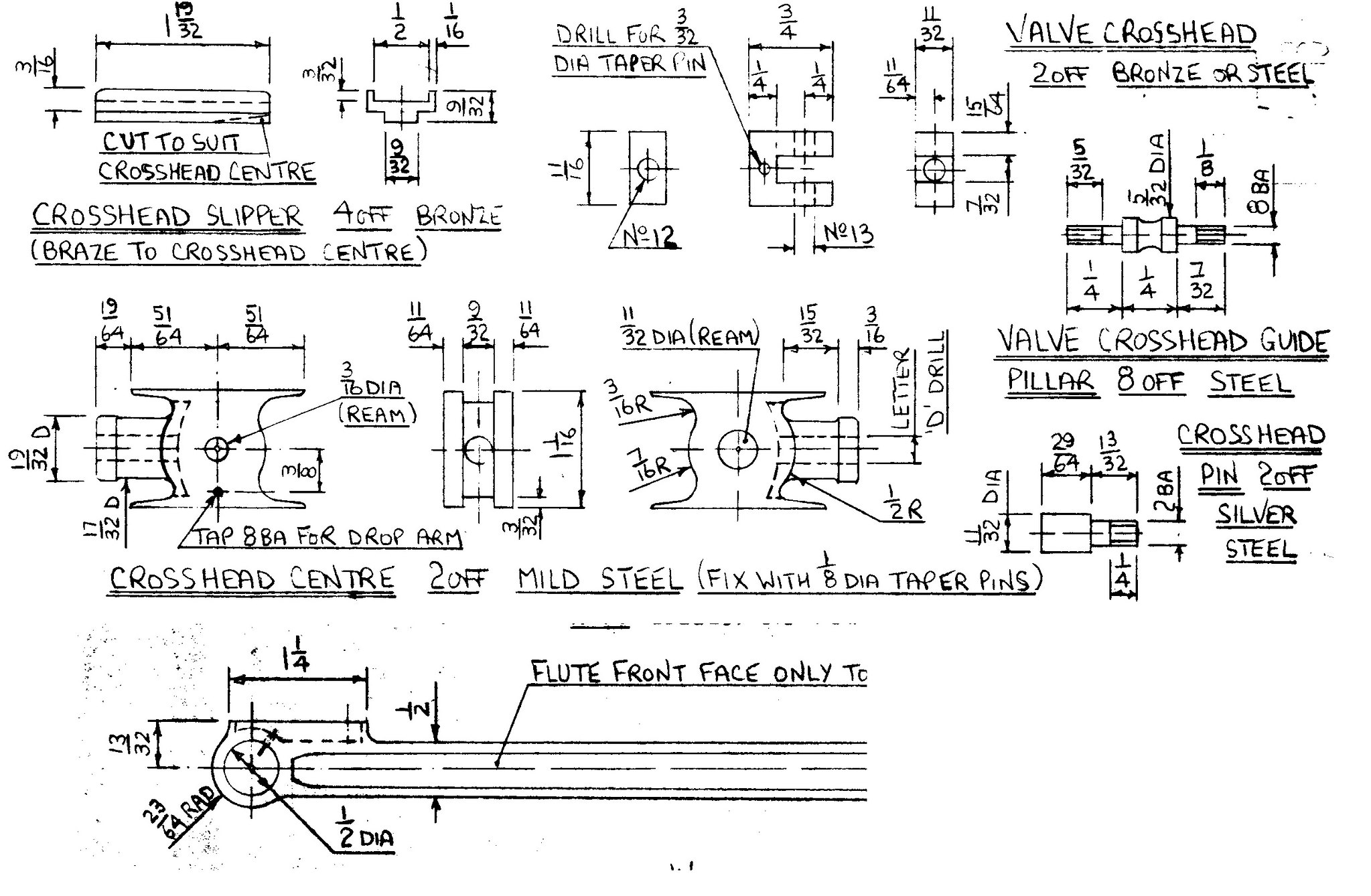 crosshead crosshead by Brian Leach, on Flickr |
|
|
|
Post by ettingtonliam on Feb 7, 2019 8:00:13 GMT
Yes. Can you see the curved chain dotted line just inboard of the piston rod boss? Thats the end of 9/32" wide slot shown in the end view, into which the con rod end fits. Then the crosshead slippers, top and bottom are brazed on, as per drawing, to close the slot top and bottom, but leaving it open at the end for the con rod. You don't need to know a depth for the drilling for the piston rod, it just goes through till it hits fresh air in the slot.
Don appears to be using third angle projection in these views.
|
|
Lisa
Statesman
 
Posts: 806 
|
Post by Lisa on Feb 7, 2019 8:06:28 GMT
Brian, if you look at the 'crosshead centre' drawings, there's a left, rear, and right view; the rear view shows a 9/32" slot cut right through the back of the crosshead for the connecting rod to fit into. The piston rod hole would just go right through into this slot. A 'crosshead slipper' would then also fit into the top and bottom of this slot, and the slidebars would run in the slippers. Here's a really rough 3D model of it, to help give you some idea:  |
|
|
|
Post by runner42 on Feb 7, 2019 22:44:49 GMT
Thanks Liam and Lisa, it now makes sense.
Brian
|
|
|
|
Post by runner42 on Feb 12, 2019 6:24:15 GMT
Apologies to the DY purists but I have again borrowed heavily from LBSC's Doris for the construction of the crossheads. The overall dimensions remain the same as specified by DY except that the inner cut out where the small end of the connecting rod enters is 1/2" instead of 9/32" which means a couple of thrust washers will be required to hold the connecting rod central. I have used two screws to hold the 3 piece fabrication together, however when I am confident that the connecting rod can operate its full angle of movement in the cut out I shall silver solder the parts together. Brian 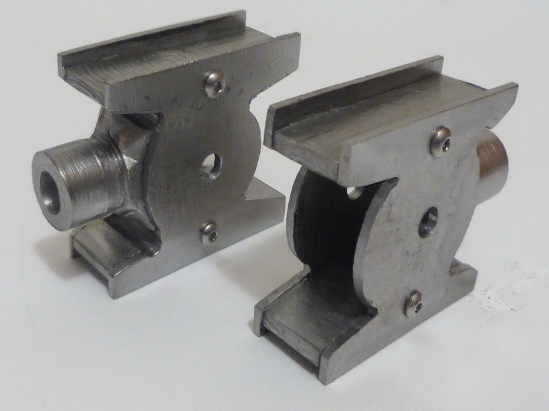 crossheads crossheads by Brian Leach, on Flickr |
|
JonL
Elder Statesman
   WWSME (Wiltshire)
Posts: 2,991
|
Post by JonL on Feb 13, 2019 9:08:32 GMT
More than one way to skin a cat!
|
|
|
|
Post by runner42 on Feb 15, 2019 6:44:57 GMT
I was hoping to have received after 6 weeks on order the driven and coupled wheels but they're still awaiting being cast at the foundry, obviously they have plenty of work which is a good thing, I would hate to see such places close due to lack of work. So I have to content myself in doing the many little jobs on a locomotive which being small don't require commensurate time, sometimes they take a much time as the bigger ones. But having the main wheels on gives one a greater sense of achievement. So the drop arms have been added. I made a small jig to enable the distance between the crosshead centre and the hole in the drop arm to be exactly 1.156". Brian 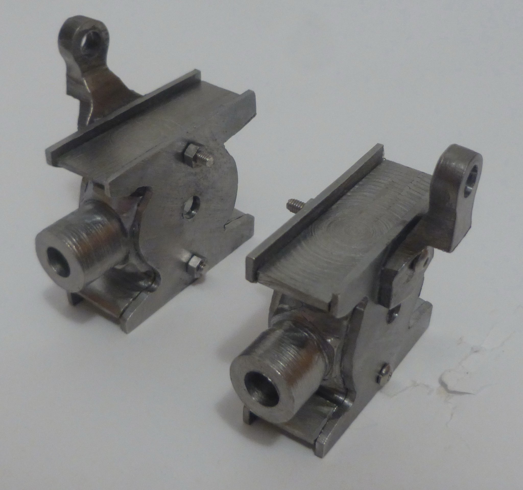 crosshead_droparm crosshead_droparm by Brian Leach, on Flickr |
|
|
|
Post by runner42 on Feb 18, 2019 6:18:24 GMT
I thought I might try a WIP section thereby exposing my model engineering skills (or lack thereof) to all and sundry. A big challenge for me is the connecting rods mainly because of the size and the amount of milling required. My approach is based on what raw material I have that is suitable. I have a length of 50mm x 12mm steel flat bar which if cut to length would not quite make two because the height required at the big end would be 1.2187", which twice that is greater than 50mm (1.968"). But the big end can be extended by silver soldering a piece on, which would not affect the strength because the hole size required for the big end bush is contained within available material. See drawing.  connecting rod connecting rod by Brian Leach, on Flickr The only means of cutting the bar lengthwise is a hacksaw, but attempting to cut by this means for over 12" is out of the question, so chain drilling is used instead. My first task is to drill the holes for the small and big ends, the small end diameter is 0.5" which is the limit of my drill size so the big end hole size of 11/16" will have to be bored on the mill using my boring head. (thanks to Lisa that I acquired one else I would have met an impasse). 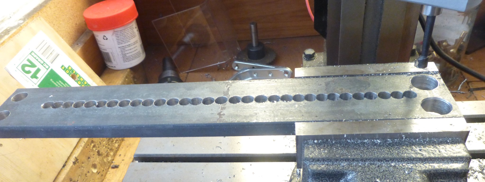 connecting rod step1 connecting rod step1 by Brian Leach, on Flickr The chain drilling was used within the middle section leaving gaps at each end and the distance from each end is governed by the requirements of the profile. These sections were hacksawed for separation.  connecting rod step2 connecting rod step2 by Brian Leach, on Flickr After separation  connecting rod step3 connecting rod step3 by Brian Leach, on Flickr I now have two blanks that I can mill hopefully in my mini mill Brian |
|
|
|
Post by Deleted on Feb 18, 2019 12:04:37 GMT
Hi Brian
Not knowing the material concerned, you may find it prudent to normalise before doing any machining or the metal may bend/warp/
Pete
|
|
|
|
Post by Roger on Feb 18, 2019 14:03:24 GMT
Out of interest, I made an extension for the frame and blade for one of my hacksaws so that it's possible to saw much longer items than would usually be possible. It's not the sort of thing that gets used very often, but it's invaluable for the sort of job you're doing.
|
|
|
|
Post by terrier060 on Feb 18, 2019 14:30:43 GMT
OOOOH! that's a lot of holes Brian - well done! Done the same many times when making clocks. Then used a piercing saw to cut out.
|
|
stevep
Elder Statesman
  
Posts: 1,073
|
Post by stevep on Feb 18, 2019 17:11:34 GMT
Normal hacksaw frames allow the blade to be mounted at 90 degrees - so sawing down the row of holes would be easy.
Doesn't work so well on wide materials.
|
|
|
|
Post by runner42 on Feb 19, 2019 6:27:23 GMT
Yes I am aware that the separation could have been done using a hacksaw, but I chose the chain drilling method because it could be accomplished much sooner, hacksawing through a 12mm thick bar for 12" is NOT easy, also the size of drill I chose was the largest I could accommodate that could be used without impinging on the profile of each connecting rod. A hacksaw blade width is small so I would have to remove more metal on each side after separation. So effectively I used a labour saving method that leaves the blank closer to the required profile. A bit of a wasted day, I am not ready to undertake the milling of the connecting rods. Although I scratched my head wondering how I was going to set them up, after a lot of poncing around for half a day, I came up with the setup shown which appears to give a rigid holding. However, the milling machine is my nemesis because it doesn't do what I expect. It maybe due to lack of experience or more likely being a mini mill that it requires a greater understanding of its limitations to be able to use it effectively. The setup shows that the most typical movement would be to operate the X axis wheel and have the cutter traverse the full length of the connecting rod. To operate the X axis wheel for that length requires a lot of turning. i.e. 152 rotations. If the turning is done by cranking the handle this causes a crabbing action of table which is deleterious, so to have to put the gib screws up tight to minimise this but then the turning effort becomes much greater. I have been told by Jason not to crank the handle but to grasp the handwheel and turn it that way. This is slower and on a 12mm wide bar using a 8mm endmill requires two passes for each metal removal, so 304 rotations plus 152 rotations returning the table to the beginning so as to avoid climb milling. Well that's the nature of the beast you say that's what you've got to do, but everything that was setup at the beginning doesn't last for the full 12" transition, vibration occurring during the run causes the gib screws to undo and the crabbing action is again evident. Lastly, the mill has a little 3 mm or 4 mm clamp for the X and Y axis, which is useless, it doesn't stop the table moving in the Y direction when traversing the X direction. What you see in the picture is a connecting rod blank that had the metal ground off using an angle grinder, I can achieve more using this than poncing around using the mill. It cannot be used for precision work but it gets you to that point quicker. Please if there is any suggestions on what to do with improving my milling experience/machine then let me know. Brian 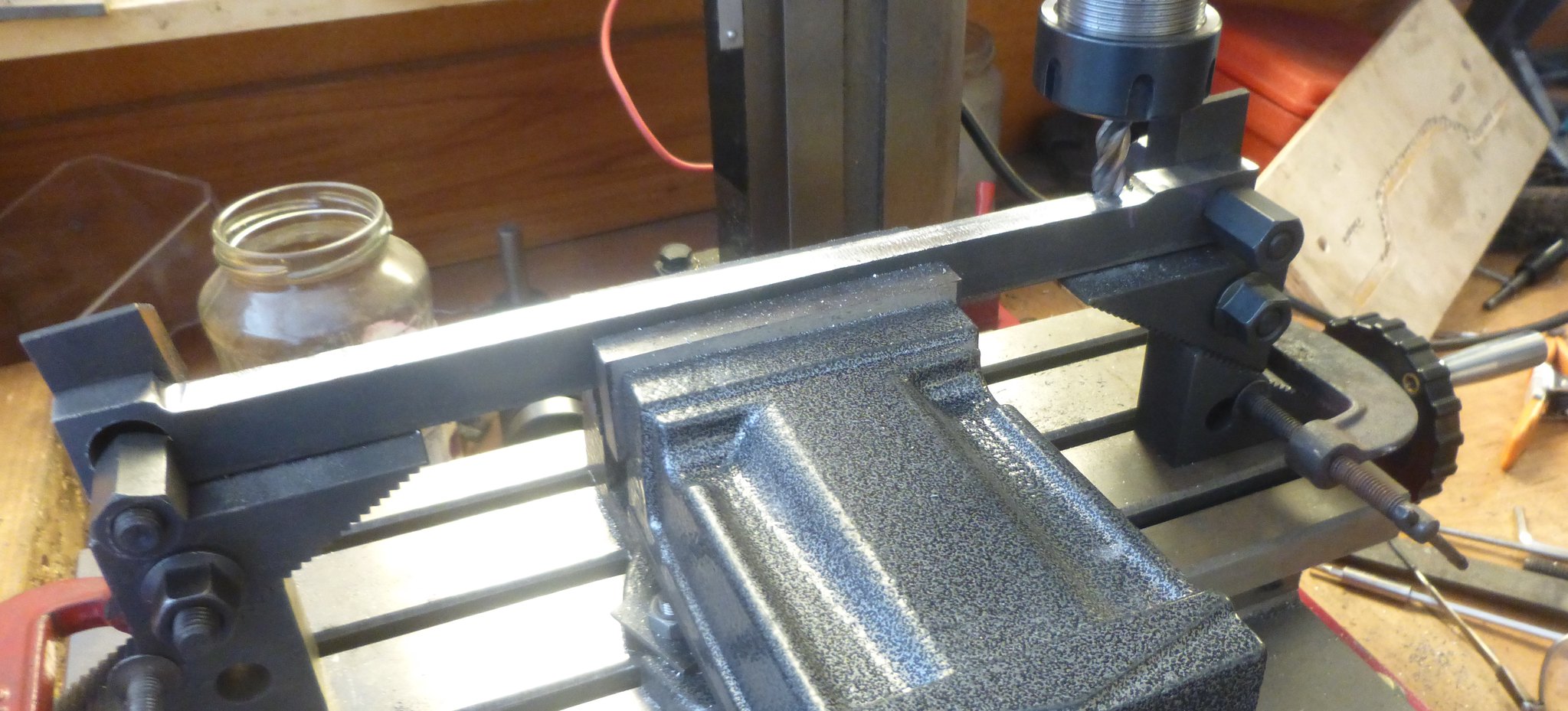 setup connecting rods setup connecting rods by Brian Leach, on Flickr |
|
|
|
Post by ilvaporista on Feb 19, 2019 8:59:24 GMT
I confess to also using the angle grinder for mass material removal prior to milling. Best done outside if you can as the dust goes everywhere. One thing I do is drill a number of small holes to act as a guide when you are close to the surface, this is not so relevant if you have chain drilled to rough shape. These tell tale holes let you know when you are close to the required size and when they just about disappear it's time to stop. Like you the idea of sitting at the mill with multiple hand turns for hours put me off. To overcome the boredom I fitted an old style windscreen wiper motor (those with the crank mechanism external to the motor) with a small pinion and replaced the hand wheel on one end with a large mating gear. The motor is held on Dexioin type slotted angle and when required is bought in to mesh with the large gear on the feedscrew. The motor is controlled by a model railway speed controller so I have variable feed and reverse direction. Took a couple of hours to 'bodge' together and was meant for one job. It's still there 10 years later... Cost was next to nothing as I had all the parts sitting round me. Extra refinement is by microswitches on the table to stop the motor. I can leave a big job by itself whilst I do something else close by. I hope this link works which shows the drive unit in the foreground. i1290.photobucket.com/albums/b534/ilvaporista/DSC_0074_zps2g3vpnqh.jpg |
|
|
|
Post by Roger on Feb 19, 2019 10:21:43 GMT
Hi Brian,
Just s few thoughts...
You might be better off clamping the rod directly to the bed in the other orientation and machine it from the side. It could be supported by some scrap material or hanging over the edge of parallels. The point being that you could them clamp it in multiple places for a really rigid setup.
I wouldn't use ball nosed cutters on a manual mill unless absolutely necessary. I presume you're using that to get the end radius?
It sounds like you might benefit from modifying the gib strip locking screws so they can't vibrate undone.
Yes, moving the handle by grabbing the outside and carefully and smoothly passing it from hand to hand is what's necessary in my opinion. That's how I'd do it manually on the lathe too.
I suspect that an 8mm end mill is too big for the mill, it looks pretty light. You would probably be better off going with say 5mm cutters. Yes, you would have to change to a bigger one to get the end radius, but it doesn't matter what the size is for the flat part.
I'm afraid it's going to be a long and tedious job because the machine just isn't rigid enough to let you crack on with it. You might consider doing what Doug has done to his mill ie add some substantial channel to the column to made it more rigid. CNC on a light machine makes life a lot easier because you can set it to do lots of tiny cuts that you'd never have the patience to do manually, but the machine will cut smoothly and easily.
|
|
|
|
Post by Deleted on Feb 19, 2019 11:36:50 GMT
Hi Brian
Just to add to what's been said, you would find it quicker in the long run if you make a jig to hold the rods, you can see what I did in my own thread as an example. In essence, it was a large piece of steel, perhaps 2 x 3 inch and long enough for the rod in hand, alas I can't remember it's exact size. There are a number of advantages, it will act as a heatsink to help reduce heat build-up which is why the steel bends, it will give a much more rigid setup but of much more use is it gives you a datum to machine multiple rods from. What I mean is once the jig is set in the machine vice (or whichever fixing method you prefer) you can do a number of cutting procedures without needing to remove the jig or reclock the rod's position. So for the job you're doing now, with the jig set, you can machine the top, bottom and both sides without worrying about stopping the cut in the correct place as it will be the same for the top/bottom and the sides will also need to be equal to each other. All you do is undo the bolts that hold each rod through its holes and either turn the rod over or change one side for the other when machining the sides. With the end start positions noted you just do each side the same and then repeat for the next rod, once the profile is done you also use the same jig for machining the flutes. This alone saves an awful lot of time messing around setting up for each operation.
Just trying to pass on my own methods, I'm sure there are plenty of other ways of doing things, at the end of the day, it all comes down to what's best for the machinery that you have to hand....regards
Pete
|
|