|
|
Post by odc on Oct 31, 2008 9:21:17 GMT
David, are you member of my North London club  Looks like another one........Dave if you talk to Derick Perham and Brian Apthorpe they are both building Black 5s. Brian hopes to run his next year. I don't know whos plans they are building from, however. Owen, see you are my talk next week?  |
|
dscott
Elder Statesman
  
Posts: 2,440
|
Post by dscott on Nov 4, 2008 11:48:42 GMT
And there is possibly another in the shape of the standard 5, which is the modernised black 5 which may be drawn out by Doug Hewson one day, as once the standard parts are produced these will fit all the B.R. Standard designs to total scale.
Saying that the black five is a wonderful engine.
David.
|
|
|
|
Post by Laurie_B on Nov 4, 2008 17:37:58 GMT
And there is possibly another in the shape of the standard 5, which is the modernised black 5 which may be drawn out by Doug Hewson one day, as once the standard parts are produced these will fit all the B.R. Standard designs to total scale. Saying that the black five is a wonderful engine. David. A few years ago I acquired this very nice 5" gauge BR Standard 5 that had been built by a guy in Cheshire,and I've now restored it to running order. I believe there are two more 5" gauge Standard 5's under construction in the Bournemouth/Poole area. I'm not sure Doug Hewson is planning on designing a Standard 5 at the moment-I think his next project might be the 2-6-0 Class 4 tender loco-the ones numbered in the 76xxx series. Doug tells me he is planning to write a book on models of BR Standard steam locos.  |
|
dscott
Elder Statesman
  
Posts: 2,440
|
Post by dscott on Nov 6, 2008 12:56:33 GMT
Lovely positioning of the loco in the background, of course the Black 5 is a much easier to maintain GWR hall painted black!!!!!!!!
David.
|
|
sapper
Involved Member
  
Posts: 73
|
Post by sapper on Nov 13, 2008 18:37:40 GMT
A number of componts that were used on the Stephenson version of the Black 5 ie 4767 became standard on the BR version. For example the springing arangement on both the tender and loco are more or less indentical. The castings that Doug Hewson used for his Class 4 tank are also the same.
|
|
abby
Statesman
 
Posts: 927
|
Post by abby on Nov 16, 2008 18:14:57 GMT
Hi all , having read all of your posts regarding the cost of castings I have started a project to manufacture cylinder castings for Don Youngs Black 5 , hopefully at a price you will not be able to complain about . I am presently at the 3D cad modeling stage and seek opinions on the provision of inlet passages. The inlet passages , as builders will be aware , are shown on the drawing as being 2 off each end , sized at 1/4"x 3/16", and spaced so as to clear the cylinder end cover bolts. My problem is this , if the passages are arranged as per the drawing they break into the cylinder wall quite some way down the bore , can anyone enlighten me on this point and the shape of the ports as from a front view ?  |
|
|
|
Post by drjohn on Nov 17, 2008 9:44:29 GMT
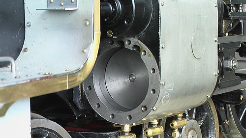
Horror upon horror, he's back! And I promise to try to suppress the acerbism!  However, when I see that Abby is kind enough to try to help Black 5 makers, if it is of any help, Abby, I do have the Reeves castings for the Black 5 cylinders and can send you detailed photos and measurements if that would be any help. Here's a pic of the front view:-  As you can see, the Reeves ones do not have any casting indents for the cylinder steam ports which you are showing on your post. DJ (on his best behaviour) |
|
|
|
Post by circlip on Nov 17, 2008 13:54:41 GMT
How long before it drops back to the normal acerbism ;D Whose taking bets  |
|
Myford Matt
Statesman
  There are two ways to run a railway, the Great Western way, and the wrong way.
Posts: 621
|
Post by Myford Matt on Nov 17, 2008 14:04:22 GMT
Hi Abby
Does this mean you are now doing CI as well as GM castings?
Cheers
Matt
|
|
abby
Statesman
 
Posts: 927
|
Post by abby on Nov 17, 2008 17:01:45 GMT
Many thanks for the picture DJ , have you machined these yet ? I would be interested to hear your views , and comments on any improvements you may think possible.
Sorry Matt no cast iron as yet , the drawings specify CI or gunmetal and I will go with the latter.
|
|
|
|
Post by baggo on Nov 17, 2008 17:43:31 GMT
Hi Abby,
Don's construction notes say about drilling the passages:
"file flats at the top of the bore as the start of the steam passages, centre pop and then drill No.11 (0.191")."
The drillings are then elongated with a 3/16" endmill.
My understanding of that is that the drilled holes must be almost completely in the end wall of the cylinder as it would be very difficult to drill a hole half in the end of the casting and half in the bore! However, the flat filed to start the drilling will be at an angle to the end of the cylinder and the bottom edge will enter the bore slightly.
I think the drawings are a bit deceptive. The general arrangement of the cylinder shows the passages reaching right to the very end of the cylinder bore but the cross section of the cylinder does indeed show the passages breaking out part way along the bore.
I presume you are thinking of casting in the passages?
John
|
|
abby
Statesman
 
Posts: 927
|
Post by abby on Nov 17, 2008 20:43:14 GMT
Hi John , yes it is my intention to include all the passage ways in the casting, but my 3D model shows that the inlet passages as drawn , ie. within the pitch circle of the cylinder bolts ,would break out almost 1/4" down the cylinder bore, if the passage way was formed by drilling it would have to be centered on the edge of the bore - I would do this , like most , by plugging the bore - but the edge of the hole will still be well down the bore. I suppose what I am really asking is if this is correct ! I should hate to produce something that is wrong. I hope these pictures explain my thoughts.   |
|
44767
Statesman
 
Posts: 539
|
Post by 44767 on Jan 8, 2009 9:54:51 GMT
Hello Everyone,
I have just been browsing this forum and found this thread. As you can see from the thread "My George!" in Images, I am building 44767 to Don Young's drawings. Tomorrow, when it is light again, I'll take the front cylinder cover off and photograph what I have done as far as the ports go.
Any other info I'll try to help with too, but once one has found a mistake and rectified it, the drawing doesn't always get noted with "as built" alterations. There is one I do remember though on the 4767 version is the amount the lifting crank is offset. I made a beautiful job of them at first and found that when I assembled it the expansion link was out of position by about 3/32 to the valve rod.
I have scores of photos of the full size if anyone needs details not on the drawings. Just PM me or post a note here.
Regards to all other builders, Mike
|
|
44767
Statesman
 
Posts: 539
|
Post by 44767 on Jan 10, 2009 5:08:54 GMT
As promised a view of the cylinder with the cover removed:  I am fairly sure that I started the hole almost entirely on the face. Then I milled the passage from the holes to the bore making that about 0.125" deep. The end cap has a 1/16th spigot on it so this leaves an orifice 1/16" wide. I will also mill a pocket corresponding with this in the end cap to allow a better flow. I'm not sure how you'd arrange the core in the casting- maybe have it stop short of the end and then just break through with an end mill once the bore has been machined. |
|
abby
Statesman
 
Posts: 927
|
Post by abby on Jan 10, 2009 6:29:46 GMT
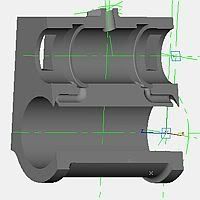
Many thanks for all the input, my main thought was that the breakout into the cylinder end face seems a bit pointless as the clearance for these that is made on the end covers is minimal. I appreciate Drjohn's comment that the engine has adequate porting but I wanted to do something a bit more elegant , even though it is hidden. Perhaps this cut-away will explain my thoughts !  This keeps the faces intact and lessens the risk of steam leaks - if any |
|
dscott
Elder Statesman
  
Posts: 2,440
|
Post by dscott on Jan 12, 2009 11:08:03 GMT
For a complete change, I bought this months Railway Modeller as in my youth did build several models of railways, but got fed up in the end over the my gauge and scale is best problems in the early 80's. 16.5mm 18.00mm or 18.85mm or 9mm or 9.45mm gauge???
Well this month shows the building of a Black Five and the great thing about looking at a model made, is that all the research is done for us and all we have to do is copy it into a bigger size.
It is also interesting to note that there are 18 preserved, and there is a lovely drawing within the text.
David.
A long time admirer of these engines.
|
|
abby
Statesman
 
Posts: 927
|
Post by abby on Jan 20, 2009 0:11:46 GMT
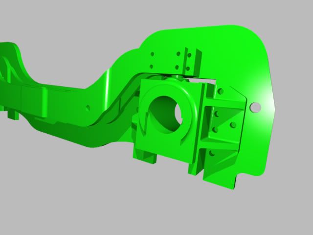
Can any one sort out a small problem that I have encountered , the equaliser beam on my model does not fit. I have checked the parts to drawing and cannot find any mistake in my work so is the mistake on the drawing ? this photo should explain , with the balls located in their respective sockets the bolt holes are miles out.  |
|
44767
Statesman
 
Posts: 539
|
Post by 44767 on Jan 20, 2009 9:47:37 GMT
I have just checked my drawing and everything ties up OK. The axle center is 6 29/32. The equiliser beam is 7 17/32 O/A - 2 x 3/32 - 2 x 7/32 = 6 29/32. Have you allowed for the joggles in the side plates when they were marked out before they were bent?
|
|
abby
Statesman
 
Posts: 927
|
Post by abby on Jan 20, 2009 11:45:23 GMT
Problem sorted , after getting some sleep I realised that I had made a mistake converting fractions to decimals ... oops ! but having done the correction the beam fits perfectly into the housings,
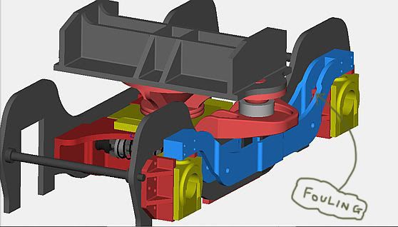
Now the beam just fouls the horns with the bearings in the raised position ..... grrr
|
|
abby
Statesman
 
Posts: 927
|
Post by abby on Jan 22, 2009 7:14:44 GMT
I have just completed the 3D cad model of the bogie for Don Youngs Black five in preparation for designing a G1 version, As I said in my last post I find the equaliser beam fouls the horns at each end. Whilst I can work around this I wondered if any one had found this problem or have I made a mistake somewhere ? everything else fits perfectly. Are the nylon sockets for the bolster fixed in any way ?other than by the weight of the loco.  |
|