|
|
Post by David on Nov 6, 2023 9:53:48 GMT
Thanks guys. I did put a groove in the middle of the axle shoulder for this purpose but not the crank pins. I did twist the crank pins as I put them in so with luck some loctite got into whatever bits of rough were left by the reamer. Here's how I put the wheel back onto the mill to ream the hole. Think of how much easier this would have been RIGHT AFTER THE LAST DRILL as all the others were done! I was able to put this wheel over one of the others and have both crank pin and axle go through so it's pretty good. That only worked for one other wheel so there are tiny differences between them - hopefully less than 0.001"  The wheel is sitting on the wheel making jig which has a 1/2" reamed hole to locate the axle hole and another one of those at crank pin distance on one side, and a clearance hole for drilling and reaming opposite - which is under the crank pin hole in this photo. Then a centre was used to put the crank pin hole under the spindle and everything locked down. Here are the other new bits.  |
|
|
|
Post by racinjason on Nov 6, 2023 22:16:20 GMT
Those wheels look good David, it's satisfying machining wheels from solid and that exhaust should let it breath. when I use Loctite on pins or axles, I leave the finish a bit ruff a drilled hole is good then make the shaft a push in fit this give a surface for the Loctite to key to also put the Loctite on the shaft not the bore this will push it down the shaft as it goes in.
Regards Jason.
|
|
|
|
Post by David on Nov 7, 2023 6:23:13 GMT
The tyres look fantastic in person, a really great finish. The steel wasn't anything special, just MS covered in mill scale.
I wish I'd left the counterweight flush with the boss and tread - would have saved time, wear, and looked better! I'd also make the spokes thinner. Pretty happy with them for a first attempt and only scrapped one because I used the wrong cutter.
I'm considering making 3mm bosses for them because I think they'll look a bit silly with a 3mm bush bringing the rods out to the correct spacing.
|
|
|
|
Post by racinjason on Nov 7, 2023 8:15:54 GMT
David,
did you turn the tread on the mill?
|
|
|
|
Post by David on Nov 14, 2023 9:53:54 GMT
Yes, the treads were done with the CNC lathe head.
I've made the front crank pins just a bit too long, thinking too long was better than too short. I was wrong! The instructions do say the crankpin is very close to the crosshead and that is true. The crankpins are loctited into the wheels now so it's going to be a bit of a mess getting them out but I assume some heat will do it so I can shorten them. I'd have been tempted to file them back but they have a counterbore in them that a top-hat bush goes into and the bush will bottom out if I do that so the excess has to come off the rear of the pins. I might re-measure in the light of a new day and see if that will work because it will (may?) save a lot of faffing around. Unless I get it wrong and have to buy a new length of silver steel to make new ones.
Far worse is that I read a drawing incorrectly and thinned the front axleboxes down to 1/2" over all rather than 5/8". I didn't check the existing ones to confirm the measurement either. This means they're too thin to have the spring pockets drilled into them. So that's many hours and much careful work wasted. I took great care and thought through the process to make all four in a way that would cancel out errors and I reckon I probably got them all within 0.001". There's no chance I can repeat that given the centres are a little off fore-aft, but they were all off the same amount! Plus I need to buy another stick of cast iron and machine a great deal of it away, again.
Quite a frustrating session with the measuring sticks finding all that out tonight!
|
|
uuu
Elder Statesman
 your message here...
Posts: 2,856
Member is Online
|
Post by uuu on Nov 14, 2023 11:06:52 GMT
At the Pump House we've found removing crankpins with an arbour press is effective. A bit of heat helps, but we've never had to get them really hot - the press seems to do the work.
I think we're on the third set of pins for John's loco, (so far).
Wilf
|
|
stevep
Elder Statesman
Posts: 1,073
|
Post by stevep on Nov 14, 2023 12:32:08 GMT
Can't you clamp the wheels on their back to the milling table, and gently machine off the excess?
If you need to drill and tap them deeper, you could 'clock' them true to the spindle.
|
|
|
|
Post by David on Nov 17, 2023 8:15:09 GMT
Steve, that probably won't work for various reasons. I don't have enough material to make new ones so I'm trying to go the safest way.
|
|
|
|
Post by David on Dec 2, 2023 10:56:19 GMT
Nearly back to where I was 2 weeks ago! I got one more axle box out of the original cast iron and my father-in-law gave me a scrap of his that I could get the other from.
As expected they have a different error to the originals. I still don't know why I can't get these holes in the middle - it should have been a simple case of an edge finder on the jaws of the vise but damned if I could get it. I was close on the originals as evidenced by the rods going over the axle ends ok (a few thou out) but these ones are much worse, relatively.
The design calls for 8.625" between axle centres. Using an edge finder on the milling machine I ended up with 8.641" +/- 0.001. So I reckon I managed about 0.012" error on these ones!
As best I can measure the current rod boss centres are 8.633".
I'll knock the front bush out, put a new undersized one in and try to bore it at the correct length and see what happens.
I also cleaned the axle boxes up height-wise. I trimmed the bottoms all to the same length from the axle centerline and then did the tops. I hope this means distortion of the geometry due to the axles being at slightly different heights will be minimised. Why weren't they all the same already? I have no idea, I tried very hard but didn't get it.
Spring pockets and oil galleries still need to be done on the axle boxes too.
|
|
|
|
Post by David on Dec 7, 2023 8:14:10 GMT
Spring pockets are done. The old axleboxes didn't have oil galleries to get oil to the sliding faces. I think I might add some on the new ones because the axle oil goes in the end of the axle rather than in the top of the axlebox so I have some room. I could use the CNC machine to put a fancy pattern on them.
All the measuring I did seems to have come to nothing. I made a new bush for a coupling rod, drilled while it was in the rod clamped on the mill, indexed against the middle of the rear bush, and it's sticking in the same place the old one did - when it pins are furthest from the front. Back dead centre?
Doesn't make sense to me. I might put off worrying about it until the wheels are quartered. Trying to move a rod when there's only wheels on one side seems to be a bit iffy.
|
|
|
|
Post by racinjason on Dec 7, 2023 9:51:42 GMT
Yes, trying to rotate the assembly with only one side on will jam up every time it's too easy for the wheels to get out of phase. I wouldn't worry about fancy pattern the oil goes everywhere anyway.
|
|
|
|
Post by David on Dec 12, 2023 9:51:02 GMT
In an attempt to recover from this axlebox misadventure I've made a measuring stick to check the distance between axles. I still can't quantify the distance but I'll try and use these to scribe a mark where the hole needs to be in the bush.  |
|
|
|
Post by racinjason on Dec 12, 2023 10:39:36 GMT
David
You could machine a flat on the outer edges leaving it say 5mm from center then you can easily measure with a vernier and subtract 10mm to get the correct distance.
|
|
|
|
Post by David on Dec 12, 2023 20:28:38 GMT
I don't have a vernier long enough!
|
|
mbrown
Elder Statesman
Posts: 1,786
Member is Online
|
Sisyphean
Dec 12, 2023 23:22:20 GMT
via mobile
Post by mbrown on Dec 12, 2023 23:22:20 GMT
I am going to have to locate the vertical plane of my driving axle in order to attach the expansion link brackets at the right distance from the axle. Like you I haven't got a vernier or caliper long enough, so a copy of your trammel would be just the job.
Thanks for the idea - I'll put it on my 99 3462 thread when I get back in the workshop and have a chance to make one.
Malcolm
|
|
|
|
Post by David on Oct 28, 2024 9:27:04 GMT
I've been spending my workshop time helping a (retired) work mate build a little horizontal single cylinder engine. That's nearly finished, just the valve rod to go and details here and there. It seems quite free and I think it is going to run really well.
I was quite discouraged by the axlebox stuff up so haven't been doing much on this loco.
I decided I wasn't going to get it fixed without doing another 4 boxes and that wasn't happening. I bodged the originals by screwing some 3mm steel on the rear faces of the boxes I'd machined too narrow which allowed the spring pockets to fit. I really wanted this loco to go back together without such kludges but it will always find a way to thwart me.
I quartered the wheels yesterday using a janky setup on the lathe but it seems to have worked. No eccentric bushes and the rotation with the rods on is not too tight so I expect they'll wear in quickly. Or the crank pins are moving. I'm not sure which yet.
I wanted to post some photos but imgur isn't allowing facebook logins and their instructions for working around that don't work either. So no pictures :(
But that's all good news. Wheels on, new slip eccentric bits made (and on the axle!), eccentric straps are refurbished. Time to put the cylinders on and make new valve rods. Everything needs valve rods ATM.
|
|
|
|
Post by David on Nov 4, 2024 8:43:11 GMT
Both valve rods were made in a 9 hour marathon on Sunday. How it took 9 hours I don't know, but it did. They must be longer than the originals because I had to extend the thread on the valve spindle that goes through the valve nut to bring the valves back. I may shave 1mm off the flat part of the eccentric strap to help out here.
It should be able to run on air again soon. One side is timed, but I ran out of puff before the second got done.
I fixed the broken off screw at the left-front cylinder. Careful drilling with a 1.6mm carbide drill got the process started and a 2.5 mm drill finished it. I ran a tap through and the original thread seemed undamaged. I had to take rear cylinder cover off (so piston out) to sit the cylinder upright in the vise so I cleaned off the mating surfaces and used a Loctite flange sealer when I put them back together to see how it goes.
I took the boiler & fittings out of the bin they've been sitting in since late last year and they look awful! I'll have to make some clean pickle, clean as much crud off as I can, and try again. Slime, caked on crud, paint coming off, copper furry bits, you name it! I was either going to repaint or clad it anyway so no great loss.
After a lot of head scratching (and Autodesk having misplaced my wheel model so I couldn't cut raised bosses anyway) I have decided to shorten the front crank pins by about 2mm. The rear of the little end pin is so close at present - basically touching - there is no way of fixing the rods on that won't foul. So I'll trim the pins short then drill right through and tap 5BA, then make retainers like the 24 class has which I prefer in any case. I think the problem is I have allowed too much side-play on the front axle but nothing to be done about it with the wheels loctited on. I guess that will wear the rod bushes more but so it goes.
|
|
|
|
Post by David on Nov 8, 2024 8:55:00 GMT
I machined the crankpins on the front wheels down, tapped them more deeply, and made new retaining screws from 19mm steel with a head only 1mm thick. There's a couple of holes in the face for a pin spanner. The loco ran on air today, and seemed to run well until a stop collar slipped. I have tried to not crank down on the set screws too hard so it's wasn't surprising. Pretty good progress this week. 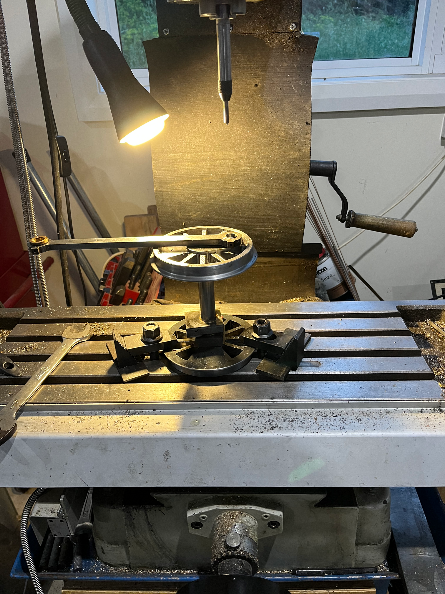 |
|
|
|
Post by David on Nov 9, 2024 9:21:36 GMT
A couple of photos taken while redoing the valve timing. Not related to the photos, I put brass slugs between the set screws and axles this time so I wouldn't be so worried when tightening the screws. The first shows the new bolts holding the coupling rods to the front wheels, the second the new eccentrics, stop collars, etc. 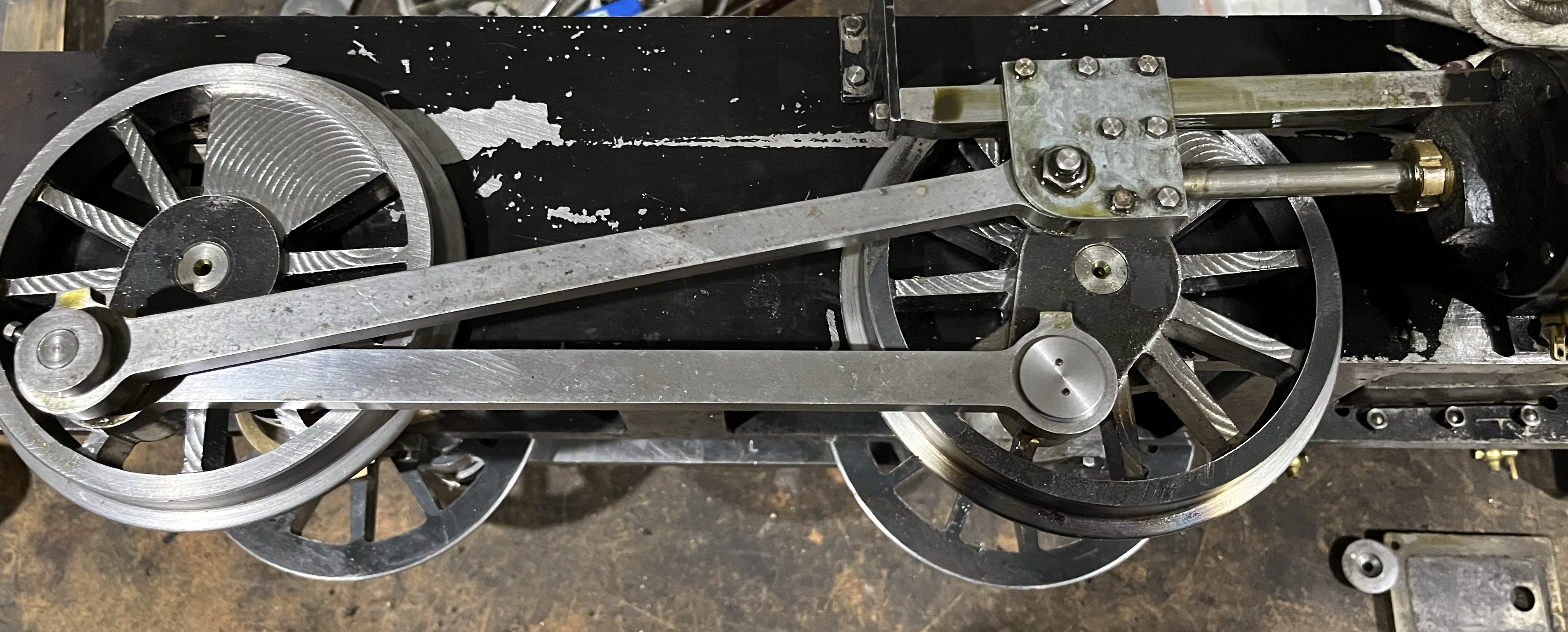 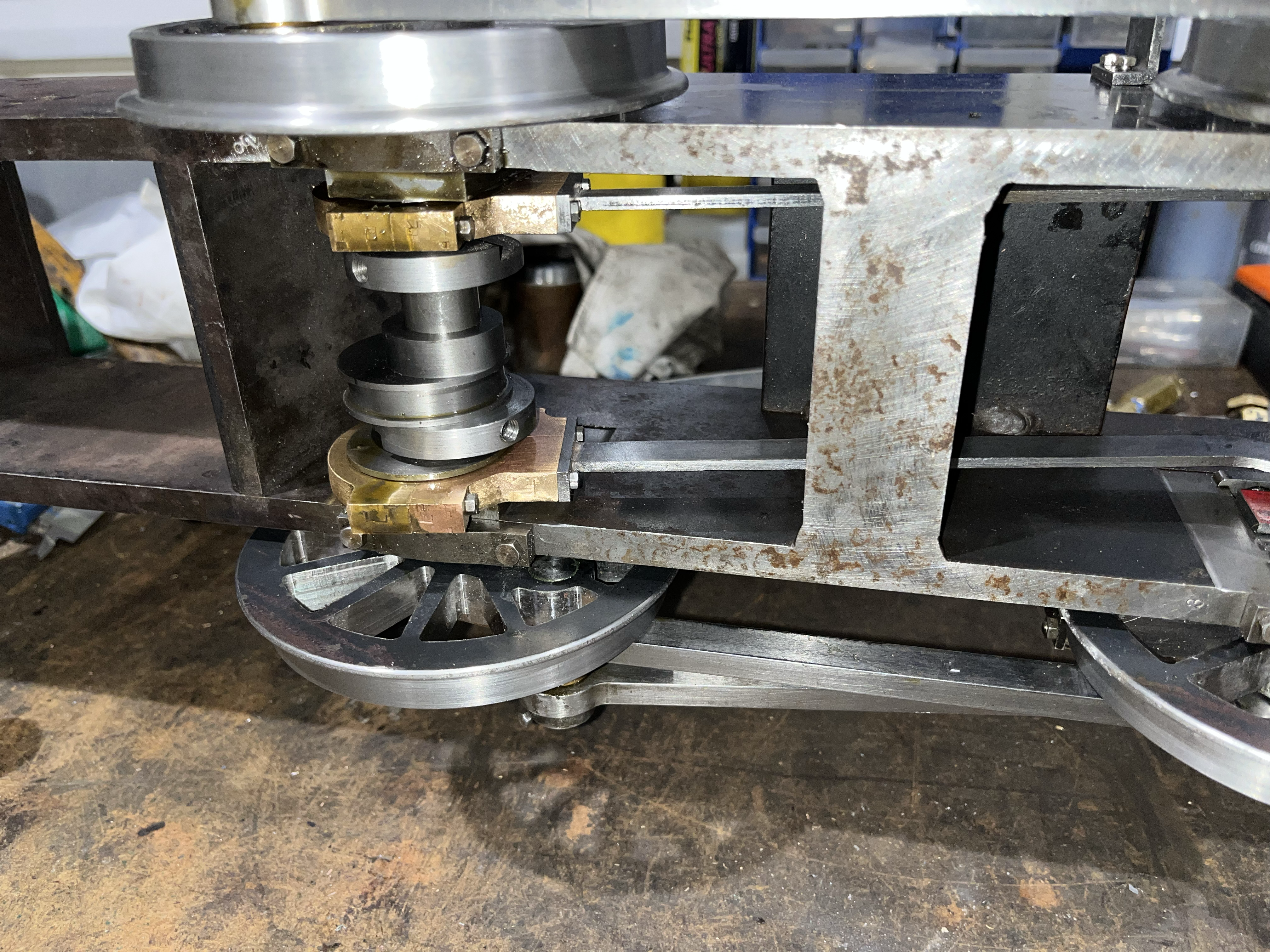 |
|
stevep
Elder Statesman
Posts: 1,073
|
Post by stevep on Nov 9, 2024 10:11:42 GMT
Do your eccemtrics have two grub screws? If so, after you have the valves set correctly, I would remove one set screw, and the brass pad, and put the screw back in so that it bites into the axle, ensuring it won't slip. (Make sure you use grub screws with points). Then do the same with the other screw.
With the brass plug in between the screw and the axle, there is a risk it will slip.
|
|


