jasonb
Elder Statesman

Posts: 1,209
|
Post by jasonb on Feb 5, 2020 7:36:12 GMT
Ignore what I said about your 0.1mm cut, I missed that you had sawn out the waste and were edge milling. Also as you are holding the cutter in a drill chuck light cuts would be the order of the day!
|
|
uuu
Elder Statesman
your message here...
Posts: 2,808
|
Post by uuu on Feb 5, 2020 8:37:12 GMT
... I'd go for Aluminium between the jaws and the part because soft material is likely to relax... An old venetian blind yields a lifetime supply of suitable material. Wilf |
|
|
|
Post by keith1500 on Feb 9, 2020 18:45:03 GMT
The next job on the flywheel was the six holes. Fairly easy stuff given a mill with a DRO and a PCD routine. My mill is fitted with Chinese rules and the Shumatech DRO kit. It’s not been bad but does have it moments. The rules don’t like oil and other contaminates and have the habit of jumping to a new number which basically means you have lost your reference and this is just what it did. Still a good squirt of brake cleaner and blow out with air cured the problem. Hole drilled out to my biggest drill. Then bored to 15mm dia.  Simple single cylinder steam engine Simple single cylinder steam engine by GL5Keith1500, on Flickr A simple drop in gauge confirms the measurement is 14.75mm the first step, the second is the 15mm diameter. It’s good to see light coming through each side which give reassurance that everything is going to plan.  Simple single cylinder steam engine Simple single cylinder steam engine by GL5Keith1500, on Flickr Next was a small grub screw. I used a vice in a vice to notionally set the angle. Clocked of the 8mm silver steel to get the centre of the boss.  Simple single cylinder steam engine Simple single cylinder steam engine by GL5Keith1500, on Flickr Attached to the silver steel using the grub screw the wheel is given a polish. This fibre stick worked well polishing in the where the holes are ( the other side is 16mm deep and too easy to damage or break a finger trying to do it by hand! The fibre stick also knocked off the burrs left from boring the six holes.  Simple single cylinder steam engine Simple single cylinder steam engine by GL5Keith1500, on Flickr As per the drawing  Simple single cylinder steam engine Simple single cylinder steam engine by GL5Keith1500, on Flickr |
|
don9f
Statesman
 Les Warnett 9F, Martin Evans “Jinty”, a part built “Austin 7” and now a part built Springbok B1.
Posts: 960 
|
Post by don9f on Feb 9, 2020 21:42:01 GMT
Looks really good and I like your "vice in a vice"!
Don
|
|
stevep
Elder Statesman
Posts: 1,070
|
Post by stevep on Feb 10, 2020 10:08:50 GMT
Looks really good and I like your "vice in a vice"! Don So do I. |
|
|
|
Post by coniston on Feb 12, 2020 21:39:22 GMT
Looks really good and I like your "vice in a vice"! Don So do I. Yet another little gem to lock away for future use. Engine is looking good, coming on nicely, well done. Chris D |
|
|
|
Post by keith1500 on Feb 12, 2020 22:07:34 GMT
Working on the con-rod. Started by placing the two holes. Then added the four holes that will form the 2mm radius. One nicety of having these holes is it is dead easy to scribe a line between these holes to show the shape and something to work to. Tonight I have been machining away metal bring the part to right thickness.  Simple single cylinder steam engine Simple single cylinder steam engine by GL5Keith1500, on Flickr |
|
|
|
Post by Deleted on Feb 12, 2020 22:37:09 GMT
Working on the con-rod. Started by placing the two holes. Then added the four holes that will form the 2mm radius. One nicety of having these holes is it is dead easy to scribe a line between these holes to show the shape and something to work to. That's similar to how I did the handles that I recently made...holes first, on my case I then placed wilmots ( think that's the word?) that fitted the holes and had the correct rad on them for producing thr handle outline.. then as you, just scribed lines between them for machining...I failed to give these details in my update though...if I detailed everything I'd never have time to make anything...  |
|
|
|
Post by keith1500 on Feb 14, 2020 20:46:08 GMT
Working on the con-rod. Started by placing the two holes. Then added the four holes that will form the 2mm radius. One nicety of having these holes is it is dead easy to scribe a line between these holes to show the shape and something to work to. That's similar to how I did the handles that I recently made...holes first, on my case I then placed wilmots ( think that's the word?) that fitted the holes and had the correct rad on them for producing thr handle outline.. then as you, just scribed lines between them for machining...I failed to give these details in my update though...if I detailed everything I'd never have time to make anything... Wilmots ? You got me there. Yes, you are quite right if you detailed everything you’d never make much progress with the model especially a big build like yours. Still, I think you have the balance about right. Keith ps I have enjoyed looking back at your middle cylinder work. Incredible! |
|
|
|
Post by keith1500 on Feb 14, 2020 21:03:45 GMT
Machining the first edge between the holes that form the radius. The part is bolted in place using purpose made bolts through the working holes. The 4mm hole has been positioned to align the machined edge on the x axis.  Simple single cylinder steam engine Simple single cylinder steam engine by GL5Keith1500, on Flickr To machine the other side the part was flipped over and some packing used underneath before clamping down. The DRO was set to zero on the final cut of the first side and used on this side. I was pleased with the outcome. 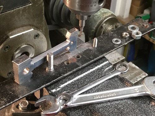 Simple single cylinder steam engine Simple single cylinder steam engine by GL5Keith1500, on Flickr The triangle conundrum The radius hole positions where worked out. Then it was a matter of finding the length of the edge to be machined and it’s angle. The same angle would be used to position the 4 mm hole relative to the 7 mm hole and so it’s co-ordinates x and y. Ignore the workings to the right. This was the previous workings! 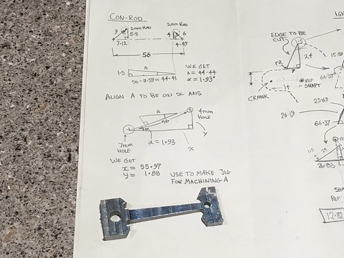 Simple single cylinder steam engine Simple single cylinder steam engine by GL5Keith1500, on Flickr |
|
|
|
Post by Roger on Feb 14, 2020 21:40:41 GMT
That's coming along very nicely. I can't help but think you would save a lot of manual working out if you just drew this up in CAD and used that to provide you will all the coordinates and dimensions you needed.
|
|
|
|
Post by keith1500 on Feb 14, 2020 22:58:44 GMT
Ditto, Roger. I have often thought how useful a cad programme would be. So far these have been relatively simple calculations which I hope have been of some interest and inspiration to others... and I use triangle calculations web sites to run the calculations. All you need is three items in a triangle to get the others. So no real pain.
I know when I was trying to improve my speedy’s valve timing autoCad, which I had at work, was invaluable.
|
|
|
|
Post by ettingtonliam on Feb 15, 2020 0:16:46 GMT
That's coming along very nicely. I can't help but think you would save a lot of manual working out if you just drew this up in CAD and used that to provide you will all the coordinates and dimensions you needed. Roger, you may find this hard to believe but we don't all have access to CAD, or, as in my case, the ability to use it. You are right though, if it is available it would save a lot of manual working out. |
|
|
|
Post by springcrocus on Feb 15, 2020 7:21:50 GMT
That's coming along very nicely. I can't help but think you would save a lot of manual working out if you just drew this up in CAD and used that to provide you will all the coordinates and dimensions you needed. Roger, you may find this hard to believe but we don't all have access to CAD, or, as in my case, the ability to use it. You are right though, if it is available it would save a lot of manual working out. Or, indeed, as in my case, the inclination to even bother learning. Regards, Steve |
|
|
|
Post by Cro on Feb 20, 2020 8:54:47 GMT
That's coming along very nicely. I can't help but think you would save a lot of manual working out if you just drew this up in CAD and used that to provide you will all the coordinates and dimensions you needed. Roger, you may find this hard to believe but we don't all have access to CAD, or, as in my case, the ability to use it. You are right though, if it is available it would save a lot of manual working out. There are so many basic and free packages out there its available to anyone so there is never an excuse. I have seen people who in the modern day are essentially 'PC illiterate' learn how to produce 3D cad models with very little effort - ok might not be the best or most efficient design from someone like my point of view who does it for a living and optimises the way we draw these things but its all doable. For what Roger is trying to suggest to aid in the machining of these parts even simple 2D drawing would allow you to draw the part up and then capture all your critical dimensions which is how a friend did all his Duchess valve gear on the Bridgeport until he learnt 3D cad and then stepped up to CNC. It's all a personal choice but as the motorised lathe was sent here to help us in the time of a treadle lathe CAD is here to improve the drafting desk! Love reading your updates by the way Keith, just because I love locos doesn't mean I don't enjoy seeing models coming together in all formats! Adam |
|
|
|
Post by ettingtonliam on Feb 20, 2020 12:07:23 GMT
The excuse is that like Steve (springcrocus) I don't have the inclination.
|
|
|
|
Post by keith1500 on Feb 20, 2020 13:41:17 GMT
The con rod and crank pin are now complete. I tweaked some of the dimensions on the crank and the con rod to prevent the con rod scraping the crank. I guess I could have fitted a thin shim in there. Anyway, here they are assembled.  Simple single cylinder steam engine Simple single cylinder steam engine by GL5Keith1500, on Flickr I guess the next job is the cross-head slider... |
|
|
|
Post by Deleted on Feb 20, 2020 15:56:36 GMT
That's looking great Keith... very smart indeed...
Pete
|
|
|
|
Post by keith1500 on Feb 23, 2020 22:32:57 GMT
Started working on the cross- slide. It strikes me that there’s a lot that can go wrong with this part. So, much criticality in the relationships of the guides to the piston rod, to the pivot of the con- rod. I started with the piston rod boss. This was drilled and tapped, and assembled. The piston rod was then clocked in the four jaw and the boss machined with a nice radius.  Simple single cylinder steam engine Simple single cylinder steam engine by GL5Keith1500, on Flickr Then piston rod was clocked level in the mill and set on centre. The guide slots milled in using a 3 mm cutter. Measurements relative to the piston rod were taken using a slip gauge and a feeler gauge to get the depth right. Both sides done leaving a few thou for fettling.  Simple single cylinder steam engine Simple single cylinder steam engine by GL5Keith1500, on Flickr The black marks aid fettling. The slot is being opened out to suit the 5mm guide. The bottom one already done. Note the scrap of 5mm square to prevent the vice squashing the machined slot in!  Simple single cylinder steam engine Simple single cylinder steam engine by GL5Keith1500, on Flickr |
|
|
|
Post by keith1500 on Feb 24, 2020 21:39:35 GMT
I should have noticed this earlier. The 5mm hole that forms the 2.5mm radius wasn’t in the right position. Odd, as this was placed at the same time as the threaded hole for the piston rod. Two choices, either start again or try to recover the job. I decided to try and recover the job by silver soldering in place a plug. The. Machine out the slot and see how it looked.  Simple single cylinder steam engine Simple single cylinder steam engine by GL5Keith1500, on Flickr Happy with the result the cross slide was then finished to size. I used two lengths of 5mm square which located nicely in the guides mainly due to the scale left from silver soldering. These sat on a pair of parallels which in turn clamped the part in place. This ensured everything was relative to the guides.  Simple single cylinder steam engine Simple single cylinder steam engine by GL5Keith1500, on Flickr The last job was the file the 6mm radius. Some of the filing was done with a file in the vice and the part moved along the file. Final filing was draw filing with a needle file followed by emery cloth guided by the roller ( filing button).  Simple single cylinder steam engine Simple single cylinder steam engine by GL5Keith1500, on Flickr The cross slide fitted beautifully and runs nicely in the guides.  Simple single cylinder steam engine Simple single cylinder steam engine by GL5Keith1500, on Flickr |
|


