mbrown
Elder Statesman
  
Posts: 1,790
|
Post by mbrown on Mar 5, 2021 11:53:12 GMT
What an inventive lot the forum members are!
I shall do some experimenting this werkend and report back... but I suspect the Jack Russell option will be drawn on only when all else has failed!
Best wishes
Malcolm
|
|
mbrown
Elder Statesman
  
Posts: 1,790
|
Post by mbrown on Mar 6, 2021 18:30:39 GMT
So today was about experimenting with felt pads in the axlebox underkeeps. I made a punch as suggested by ettingtonliam, out of 1/2" BMS with a sharply chamfered edge and a smaller hole running the length of it so that I could push the felt plug out after the cut. As you can see below, it worked a treat - cut through the felt like a knife through butter. I punched it into the grain end of piece of timber. It would certainly have done a few more cuts in felt but the cutting edge is not robust.  IMG_20210306_151130 IMG_20210306_151130 by malcolm brown, on Flickr However, when it came to cutting the felt into little pads with a radiused side to run against the axle, my problems began. Even with a super-sharp blade, the felt distorted, making a straight cut impossible, let alone one to accurate dimensions. In the end, I gave up on the idea of a radiused edge to the pad as I found that, if the felt was cut to give a bit of lateral lee-way in its recess, it was flexible enough to mould itself the the axle when assembled. So Gary is right, a curved surface is not necessary, but the contact area is a lot wider than just line contact. Next job was the axles which were simply faced off lengths of Precision Ground BMS. I took this idea from Don Young's Hunslet design but adapted it. Don used plain axles with no turned seats or shoulders and the wheels Loctited in place. The articles came out when I was building LYN and I decided to try it - but then there was an account in LLAS of a Hunslet derailing badly after one of the wheels moved inward on the axle. At Don's suggestion, I added 4 BA grub screws through the wheel hub into dimples in the axle. These are really belt and braces as I have had no trouble with the wheels moving at all. But when it came to the Burma Mines loco, which has no carrying wheels to relieve the leading coupled axle of lateral stresses, I developed the approach I am using now on 99 3462. It retains the simplicity of a single diameter for the whole axle, which ensures that reamed holes in the axleboxes, wheels and fly cranks all provide good fits, with the wheels and fly cranks secured with Loctite and (in the case of the cranks) keys, but it nonetheless prevents the wheels moving inward. Even if the Loctite bond fails, the wheels will stay to gauge. So here are the wheels, the axles, and the spacer which is a length of 15mm steel tube drilled and reamed out to 1/2" dia then faced to the back to back measurement. The sleeve and the wheels will be Loctited onto the axle.  IMG_20210306_171309 IMG_20210306_171309 by malcolm brown, on Flickr On the leading axle, which carries the pump eccentric. the spacer is simply divided in two, dimensioned so that the two halves plus the eccentric width add up to the back to back measurement. 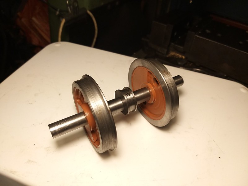 IMG_20210306_171558 IMG_20210306_171558 by malcolm brown, on Flickr I haven't yet secured all the bits together as my aerosol of Loctite Activator, unused for some years, had run out. The new order won't be here for a week or more. But in due course, the wheels will be quartered by their balance weights so that they are eventually in phase opposite the crankpins. I can't finish the flycranks until I have designed the valve gear and worked out the throw of the return crank, as this will be set when the crankpins are fitted. And I can't design the valve gear until lockdown is eased and I can visit a friend who has the right programs and sit with him to do it on screen. So flycranks and crankpins will have to wait. Nevertheless, with the wheels and axles push fitted together, the loco is now on its own wheels for the first time - a bit of a milestone!  IMG_20210306_172226 IMG_20210306_172226 by malcolm brown, on Flickr  IMG_20210306_172309 IMG_20210306_172309 by malcolm brown, on Flickr Best wishes to all. Malcolm |
|
|
|
Post by steamer5 on Mar 7, 2021 7:58:03 GMT
Hi Malcolm,
Nice work! Like the axel spacer idea!
On the felt cutting front, I had the same issue with not being able to get a decent cut, mind you your hole cutter worked a treat, I asked on another forum & was told to use a wood chisel, make sure it’s sharp & wider than the material if possible, I didn’t have one wider but had no issue, a quick wake on the end & jobs done.
Cheers Kerrin
|
|
timb
Statesman
 
Posts: 512 
|
Post by timb on Mar 7, 2021 8:13:31 GMT
On the understanding that the only stupid question is the one you do not ask....
How does the weight of the loco transfer onto the bearing surface of the axleboxes at present it appears both top and bottom are open from the photo?
Tim
|
|
mbrown
Elder Statesman
  
Posts: 1,790
|
Post by mbrown on Mar 7, 2021 10:02:02 GMT
Hi Tim,
Not a stupid question as it isn't obvious from the photos.
In the photo with the chassis upside down, the hornstays are missing as the axleboxes are only in position temporarily.
In the "right way up" shot, you can see the tops of the boxes because I haven't made the springs yet. These are leaf springs with the buckle bearing on the top of the axlebox and the ends supported by pins which are fixed to the frame by the little pockets just fore and aft of the axlebox. The spings between the first and second and third and fourth axles are compensated so you can see the pivot brackets for the compensation levers in those locations.
Not sure when I will do the springs but I can't put them off much longer.
Malcolm
|
|
timb
Statesman
 
Posts: 512 
|
Post by timb on Mar 7, 2021 12:16:21 GMT
So will the weight be on top of the axlebox as the bearing surface - presumably the bronze - will be on the bottom?
Tim
|
|
mbrown
Elder Statesman
  
Posts: 1,790
|
Post by mbrown on Mar 7, 2021 12:51:04 GMT
That's right - the brass keep doesn't bear any weight, it just contains the oil reservoir, lifting the oil to the journal via the felt pad. The steel axle runs in the cast iron box with the loco's weight transmitted via the over-hung springs, and oil is fed from the recess on the top of the box, via small holes to the bearing surface and thus collects in the reservoir within the brass keep.
Hope that makes sense!
Malcolm
|
|
timb
Statesman
 
Posts: 512 
|
Post by timb on Mar 7, 2021 12:52:48 GMT
It does Malcolm, thank you. Great work, looks fantastic!
Tim
|
|
mbrown
Elder Statesman
  
Posts: 1,790
|
Post by mbrown on Mar 7, 2021 18:24:03 GMT
For some reason the prospect of making 12 leaf springs (8 for the loco, 4 for the tender) and another 16 spring pins didn't appeal to me today.... I don't enjoy repetition work at the best of times. So I started work on the fabricated structure which sits between the cylinders and incorporates the steam and exhaust pipes in one unit. As you can see, I shall be using commercial 6 mm and 8 mm elbows. How I am approaching this will become apparent at a later stage, I hope. But today's work was cutting out and drilling various pieces prior to assembly. There is a fair bit more drilling and boring to do yet. Eventually, the steel block will be welded into the base of the steel smokebox and the steam pipes will pass through it and serve to bolt down the smokebox to the fabricated pipework. At least that is the theory - watch this space.... More next week, all being well. Malcolm  IMG_20210307_175549 IMG_20210307_175549 by malcolm brown, on Flickr |
|
mbrown
Elder Statesman
  
Posts: 1,790
|
Post by mbrown on Mar 13, 2021 18:20:06 GMT
I like simplyloco's idea of giving the posts on a build log proper titles, so this one is called.... Steam and Exhaust Connections - Cont. ....I haven't made as much progress today as I had hoped as I had to work (the proper job) this morning, but the top parts of the assembly are almost done. I bored the holes for the breeches pipe for the exhaust to the required 3/4" diameter as I don't have a drill that size and a drill would probably have wandered anyway. With the bits threaded onto the breeches pipe, the concept begins, I hope, to make sense. The 3/16" thick top plate has been scalloped at the corners - which is necessary in order to access the cylinder fixing bolts as the cylinders have to go on after the piping assembly is in place. The steam and exhaust elbows will be fixed into the under side of this plate. Then comes a 3/8" thick brass block which will be tapped for the steam pipe connectors (the two holes to the rear). The breeches pipe has a groove for an O ring as the steel block behind will slide over it, the O ring providing a seal for smokebox gasses, and the steel plate will be bolted down to the brass plate via the steam pipe connections. As I said last time, the steel block will be welded into the bottom of the steel smokebox, so (all being well!) everything should seal nicely.  IMG_20210313_174950 IMG_20210313_174950 by malcolm brown, on Flickr Here you can see how the exhaust pipes from the cylinders will enter the bottom of the breeches pipe and how the holes merge into the base of the blastpipe. The blastpipe proper screws into the top of the breeches pipe from within the smokebox.  IMG_20210313_175229 IMG_20210313_175229 by malcolm brown, on Flickr here it all is laid in place on the loco frames. You can also see how the drilling jig, which was used to drill the cylinder flanges and the frames, is now bolted in place again and will be used to drill the side pieces of the steam and exhaust assembly. The way that lot all comes together between the frames will, I hope, come clear next time....  IMG_20210313_175013 IMG_20210313_175013 by malcolm brown, on Flickr More tomorrow, I hope. Malcolm |
|
mbrown
Elder Statesman
  
Posts: 1,790
|
Post by mbrown on Mar 14, 2021 18:48:24 GMT
Steam and Exhaust Connections Cont. 2 - Rain stopped play....Today I got the top sections silver soldered together - this will be quite a complicated assembly and doing all the joints at once will be challenging, so I am planning on three soldering operations. One to do the top sections as here, one to put in the sides and cross member, and a third heat to put in the pipe elbows and connectors. However, my brazing hearth is outside the workshop back door and before I could do the second soldering job, the heavens opened, the wind was howling and going out didn't feel like such a good idea after all... Anyway, here it is ready for the second soldering operation. The side pieces were drilled from the jig shown yesterday and then opened out by boring in the lathe. The holes are 1/16" all round larger than the spigots on the cylinders as these holes will ultimately form the pockets for O rings. The cross member keeps everything square and a nice sliding fit between the frames, and the end pieces will allow it to be screwed to the frame stretchers to keep everything rigid. 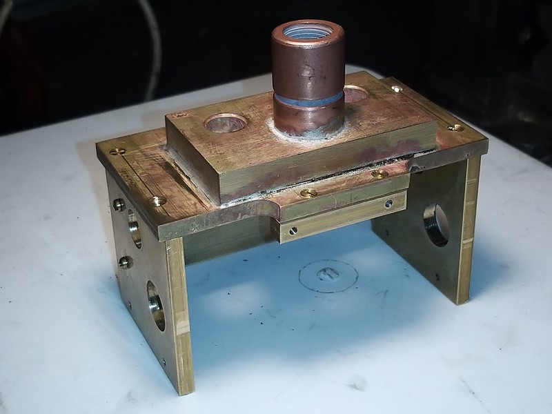 IMG_20210314_173249 IMG_20210314_173249 by malcolm brown, on Flickr 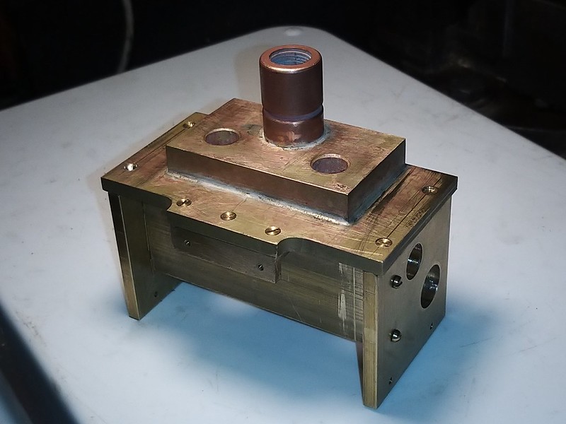 IMG_20210314_173303 IMG_20210314_173303 by malcolm brown, on Flickr Brazing this up and adding in the elbows and connectors will be a job for next weekend. Best wishes Malcolm |
|
mbrown
Elder Statesman
  
Posts: 1,790
|
Post by mbrown on Mar 20, 2021 19:05:31 GMT
Steam and exhaust connections - Cont. 3The rain which put paid to further progress last Sunday was fortuitous - over the intervening days I decided that I needed to rethink various aspects of this part. I also realised that if I silver soldered the sides and cross members as a second operation, I wouldn't be able to assemble the pipe elbows. All the remaining soldering would have to be done at one go. The rethink concerned the fitting of the O ring seals. It will be easier to show what I have done tomorrow when the assembly should be in place and the fittings are obvious. But the first thing to do was to open out the steam pipe holes in the frame from 5/16" to 7/16". For this, I made a pin drill and, running it at a very slow speed and supporting the frame carefully, it worked fine. Here's the pin drill from 1/2" silver steel. Because of the new approach, I remade the side pieces. I had run out of 3/16" brass, so they had to come out of a piece of 1/4" thick stock. I had had this lying around for ages without using it as it was slightly bowed. But as the thickness wasn't critical, it was easy enough to run an end mill over the surface which would sit against the frame. A few thou cleaned it up to be true. As a result of doing the sides again, I achieved a better fit between the frames and the whole assembly slid home like a hand into a glove.  IMG_20210320_154012 IMG_20210320_154012 by malcolm brown, on Flickr After a good deal of wangling, I managed to get the elbows and connections all assembled. I didn't photograph them until after the soldering operation. Because of the inaccessibility of the elbows etc., I made sure all the joints has rings of silver solder fitted before fluxing. It took a while to reach the right temperature but eventually all the solder pieces fused nicely. I filled a few joints that looked a little starved of solder with a stick, but I suspect it wasn't really necessary. Anyway, here it is after pickling and with a bit of cleaning up with wire wool. It will need some more cleaning, but getting into the corners is impossible for normal fingers!  IMG_20210320_181934 IMG_20210320_181934 by malcolm brown, on Flickr  IMG_20210320_181953 IMG_20210320_181953 by malcolm brown, on Flickr It should be possible to finish and fit it all tomorrow - once I have done my census return! Best wishes Malcolm
|
|
mbrown
Elder Statesman
  
Posts: 1,790
|
Post by mbrown on Mar 21, 2021 18:15:56 GMT
Finishing the steam and exhaust connections.The picture below shows how I modified the O ring seals for the steam pipes. You can see the exhaust pipe socket below, with a Viton O ring trapped between the frame and the pipe assembly. This is OK for the exhaust where only low pressures are involved, but for the steam pipes, I wanted to be able to adjust the squeeze on the O ring and to be able to remove the O ring relatively easily if necessary. So, having opened out the hole in the frame to the outside diameter of the O ring, you can see how the silicon O ring is let into the brass side piece of the pipe assembly. To give it a squeeze, I have added a collar on the steam pipe stub from the cylinder. By adjusting the thickness of the collar, I can put a greater or lesser squeeze on the O ring. And if the O ring needs replacing, "all" I have to do is remove the cylinder.  IMG_20210321_161441 IMG_20210321_161441 by malcolm brown, on Flickr Once again, the lighting and camera have exaggerated the rough finish on the frame - the scratches are just those left by medium emery cloth! Below is the collar on the stub for the steam inlet to the valve chest. The stub slides nicely into a reamed hole in the pipe assembly between the frames.  IMG_20210321_164549 IMG_20210321_164549 by malcolm brown, on Flickr And here is the whole assembly which goes between the frames, all cleaned up and with the steam pipes, which protrude into the smokebox, now fitted. 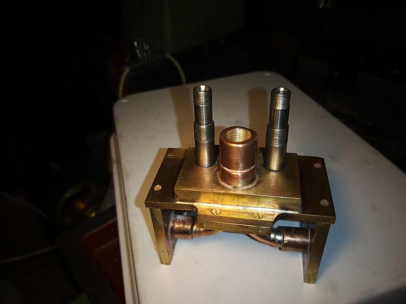 IMG_20210321_155412 IMG_20210321_155412 by malcolm brown, on Flickr And below, assembled into the frames with the cylinders pushed into place and held simply by the stub pipes at this stage. They need a strong push to mate up to the frames, so it feels as if the O rings are getting a good squeeze and should be steam tight. With the assembly between the frames screwed to both frames and both cross stretchers, it makes the whole frame assembly around the cylinders very rigid and solid.  IMG_20210321_164918 IMG_20210321_164918 by malcolm brown, on Flickr I have also assembled the steel block which will form part of the smokebox base. This is held down by the nuts on the steam pipe upstands (7/16" x 32) and the exhaust pipe stub is sealed in with an O ring. The blastpipe will be screwed into the exhaust stub (1/2" x 32) when I have worked out the draughting. Just out of interest, here is how it is done on the real thing. Here are the exhaust elbows with the steam elbows just visible at the top. But no way could I assemble all those bolted flanges between frame sonly 3.75" apart"  DSC00505 DSC00505 by malcolm brown, on Flickr That's another stage done. I really must bite the bullet and get on with the springing... I want to get that done before I finally bolt up the whole cylinder assembly as the whole thing is getting quite heavy and it will be easier to do the springs while the frame can be picked up and swing around easily. Meanwhile, as life takes its first faltering steps back to normality, all the things that have been on hold during lock down look like they are coming back. Our rowing club resumes training in a couple of weeks which will occupy my Saturday mornings (and afternoons recuperating...) and there is even some hope that trains will be running on the Talyllyn by May. So future progress might not be quite so rapid as the last year or so has been! Best wishes Malcolm
|
|
timb
Statesman
 
Posts: 512 
|
Post by timb on Mar 24, 2021 7:28:00 GMT
Some fantastic work there Malcolm, looking just great!
Tim
|
|
mbrown
Elder Statesman
  
Posts: 1,790
|
Post by mbrown on Mar 27, 2021 18:45:59 GMT
Turbo-generator experimentsToday I thought I would dig out the little turbo generator that I described a while back and see what it could do. Having got it to work, I built a simple test rig with a valve and pressure gauge on the air side and an arrangement of switches, resistors and LEDs to try various combinations. The little push button on/off switches (lower picture) are rather neat and were bought from a model railway supplier. With a bit of wangling, I think I can build them into a scale (or almost scale) switch box like the one in the loco's cab in the picture below:  DSC00478 DSC00478 by malcolm brown, on Flickr This was a standard Deutsch Reichsbahn fitting with switches to control the headlamps, tail lamp(s), cab lights and train lighting. I am planning to have the standard three headlamps, one tail lamp (which seems to have been usual on the MPSB as they had turntables at Anklam and Friedland and a triangle at Wegezin-Dennin, so the locos rarely ran in reverse. In preservation, she acquired three tail lamps), and cab lights for the water gauge and cab roof/pressure gauges. To that end, I wanted to experiment to see how the generator worked with one LED (tail lamp), two LEDs (cab lights), three LEDs (headlamps) and combinations of all six. Here is the result. At 50 psi, the generator lights all six LEDs at full brightness. Turning the pressure up further has no effect. Switching out the LEDs you can hear the generator pick up speed as the load decreases. On no load, the generator races, so it seems like a good idea to keep at least one light on permanently. (Ignore the splashes of white pain - it was the only piece of board I had to mount it all on!)  IMG_20210327_155452 IMG_20210327_155452 by malcolm brown, on Flickr I can turn the pressure down to 20 psi and all six LEDs still glow, although at less than full brightness, but 20 psi will still illuminate three of them pretty well. Below 20 psi, they all fade out. I also experimented with the exhaust from the turbine as the prototype exhaust pipe is quite narrow (scales at about 5/32") and makes several bends as it takes the exhaust up the top of the chimney. But fitting a 2" length of 1/8" copper pipe to carry the exhaust made no appreciable difference to the performance of the generator, so I can go ahead with the same exhaust arrangement as in full size. All I now have to do is make a new steam turbine. If it is to resemble the original, the steam will have to hit the wheel from the front, rather than the periphery, with the exhaust likewise exiting from the front. But given the performance of the present turbine, I reckon that will be do-able. A job for a day when I fancy something intricate and probably exasperating to make! Best wishes Malcolm
|
|
mbrown
Elder Statesman
  
Posts: 1,790
|
Post by mbrown on Mar 28, 2021 17:05:40 GMT
Starting the Smokebox I have had a piece of 4.5" steel tube hanging around for some time for the smokebox, so today I thought I'd make a start. Once the basic smokebox is done, there is lots of interesting detail on the front and the door that will be fun to make.
The tube is 1/4" wall thickness and was 5" long, whereas I needed it to be 4.4" long, The diameter is spot on for scale size.
So the first thing was to part off the unwanted 1/2". I used a 1/16" parting tool for this as I have a possible use for the offcut and wanted to save as much as I could. I also thought that a smaller cut would be less likely to dig in. The length of the tube means that it is easily knocked out of true when held in the 4 jaw chuck. I turned a bung from MDF to a tight fit and put a bolt in it for the centre to help steady the end. I pushed the bung well in with the idea that the parting tool would cut into the bung and not leave the odd end flapping around at the end of the cut. In the end, the bung wasn't a tight enough fit to offer real support, but it as probably better than nothing.
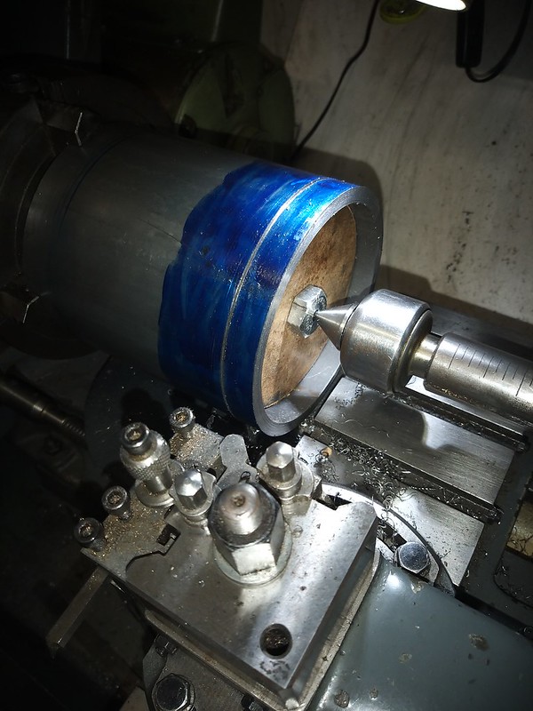 IMG_20210328_152506 by malcolm brown, on Flickr IMG_20210328_152506 by malcolm brown, on Flickr
I took the cut down until the first small witness of it emerging on the inside appeared, then ran a hacksaw down the slot to remove the last few thou without the parting tool digging in. It was then easy to face off the end nicely.
I reckoned that the 1/4" wall thickness would be unnecessarily heavy, especially as the cylinders and smokebox overhang the leading axle. So the idea is to bore it out to 1/8" wall thickness except for about 1/2" at one end which should be just the right size for the 4" dia boiler to be good fit without the complication of a separate ring. I made up a long boring bar with a tool bit ground from a broken centre drill at 45 degrees in the end.
 IMG_20210328_160415 by malcolm brown, on Flickr IMG_20210328_160415 by malcolm brown, on Flickr
This had to be taken very gently, slow back gear and the slowest feed. Each cut takes ages and I had to pack in after three passes, but it will get done eventually. Then the other end will need turning down a bit to make a seat for the cladding, and a ring of rivets put in as they were quite prominent prior to preservation. Interestingly, the prototype had a slightly uneven rivet spacing on one side - two rivets were closer together than they should be. I am not sure how to reproduce that feature and I may just try to set them out evenly!
Long weekend coming up, so more progress, I hope.
Malcolm
|
|
uuu
Elder Statesman
   your message here...
Posts: 2,858
|
Post by uuu on Mar 28, 2021 17:17:24 GMT
I wish I'd thought of the idea of leaving a ring in the back end. I've bored mine right through.
Wilf
|
|
lennart
Involved Member
   Currently building a Kennion's Chub as a first steam loco
Posts: 74
|
Post by lennart on Mar 28, 2021 19:41:44 GMT
Impressive work as always, Malcolm.
Even though it may be prototypical to arrange the rivets unevenly, I would go for an even spacing. Most certainly the people who will spot that on your model won't know about that and will think that you simply got it wrong.
|
|
mbrown
Elder Statesman
  
Posts: 1,790
|
Post by mbrown on Mar 28, 2021 19:56:08 GMT
Thanks Lennart, In the picture below (from 1958) you can see the two rivets slightly too close together at the 8 pm position if looking from the front.  99-3462-im-Bahnhof-Friedland (2) 99-3462-im-Bahnhof-Friedland (2) by malcolm brown, on Flickr Of course, my dividing system being slightly Heath Robinson, it is perfectly possible that I will get this spacing anyway - but the odds on getting it at the right point on the circumference are pretty long, I suspect! I have been trying to work out, from the visible evidence, how many rivets there are around the whole circumference. I reckon it is either 28 or 32.... probably the latter. I think I will mark them out with a scriber first and see if it looks right. Malcolm |
|
mbrown
Elder Statesman
  
Posts: 1,790
|
Post by mbrown on Apr 3, 2021 16:56:01 GMT
Smokebox - Cont.It took ages to bore out the steel tube of the smokebox to 1/8" thickness from the original 1/4" - the cuts had to be taken very gently to stop it ringing. But it was done in the end, and the front was rebated a bit further to take the front plate. Overall that has reduced the weight by about a half. Next was marking out and drilling for the rivets at the rear end. These are 5/64" dia. and the problem was finding a way to divide the circle. My rotary table is not designed to stand on its side, so doing it in the mill was out and my only recourse was to use the dividing fixture on the lathe headstock which I illustrated when doing the cylinder liners. I still couldn't work out from the photos whether there were 28 or 32 rivets around the ring - but that didn't matter as I didn't have a change wheel for the dividing fixture with either of those number of teeth or any multiple of them. So I split the difference and compromised with 30 rivets which may even have been the actual number on the prototype. Unlike the prototype, mine are evenly spaced! I used a guide in the tool post for a drill in the Black & Decker - only going in enough to start the hole and finishing them off in the drilling machine where there is less chance of breaking a No.47 drill. 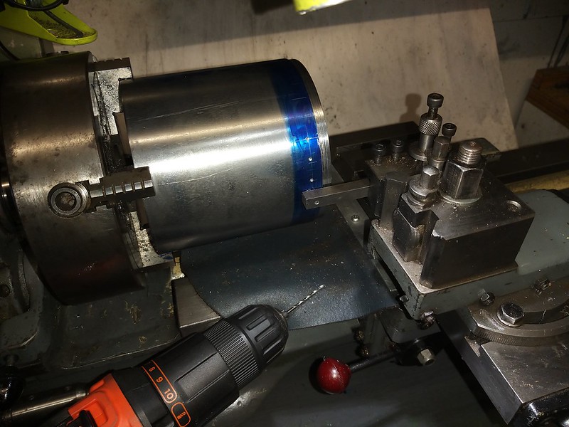 IMG_20210402_131446 IMG_20210402_131446 by malcolm brown, on Flickr In the same set-up, I marked out the top and bottom lines for the chimney and blast pipe. The blast pipe screws into the pipe assembly between the cylinders and passes through a steel block which mounts in the base of the smokebox as shown in previous posts. So with the smokebox on the mill table, a rectangular opening was cut in the base of the smokebox with ledges either side to mate with rebates milled into the block.  IMG_20210403_133351 IMG_20210403_133351 by malcolm brown, on Flickr An advantage of the fairly thick steel smokebox is that it can be held down without distorting, although the greatest pressure was exerted by the clamps at the bottom where distortion will be least. Here is the block in place. The chimney opening is pilot drilled at 1/2", and a 1/2" rod, with a bush to centre it at the bottom, passed cleanly through, confirming the alignment. I also checked with callipers that the rod was equidistant between the sides of the smokebox. Then, with the rod replaced by a long bolt and nut to hold the block in place, I welded around the joint.  IMG_20210403_144943 IMG_20210403_144943 by malcolm brown, on Flickr My welding is nothing to write home about - I only have a simple stick welder (none of your fancy TIG and MIG!) and I don't get enough practice to be confident of doing it well. So I welded from the inside for the sake of neatness. Actually, the welds came out reasonably well, although I found I had missed the corners and went back to fill them in a bit, which left a few blobby bits. The light here isn't too good, but you get the idea....  IMG_20210403_155221 IMG_20210403_155221 by malcolm brown, on Flickr And here it is, with the rivets in place and mounted on the frames. I made a small countersink on the inside of the rivet holes using a 1/8" drill in a small chuck and twisting it by hand. The rivets are Loctited in place with the shanks left a fraction over length and expanded into the countersinks with a riveting tool of the "squeeze" kind. The front plate, with its slightly raised edge around the front of the smokebox, is also in place. I turned that from a 1/2" length of tick walled steel tube. The smokebox saddle "proper" will be built up around the assembly here, just as in full size.  IMG_20210403_163136 IMG_20210403_163136 by malcolm brown, on Flickr Finally, here is the embryonic smokebox door, turned from a steel blank. Turning the domed middle part is not all that easy when the edge is flat. I roughed it out freehand with a round nosed tool, then turned it by hand with a scraper as illustrated. Getting the angle of the scraper edge just right, it is surprising how easy to is to remove metal, and by using the flat edge of the scraper, one can avoid grooves which can be almost impossible to polish out. I finished it with various grades of emery cloth and couldn't resist polishing it up with a bit of Auto-Sol chrome cleaner!  IMG_20210403_155054 IMG_20210403_155054 by malcolm brown, on Flickr There is a great deal of detail to add to the smokebox and its door, but that is all for today. Best wishes Malcolm
|
|