mbrown
Elder Statesman
  
Posts: 1,790
|
Post by mbrown on Jun 18, 2022 18:39:22 GMT
Setting the Return CranksAfter giving a lot of thought to the jig for setting the driving crankpins and correctly orientating the return cranks, the plan came together once I had looked closely at the dimensions. The idea was to put a close-fitting peg in the axle hole of the fly crank, with a vertical surface against which, the eccentric rod pin on the return crank would be pressed to set the throw of the pin exactly. The surface would have to be the diameter of the throw of the eccentric rod pin, minus the diameter of the pin itself, in order that the centre of the pin was exactly the right distance from the centre of the axle. As it turned out, this figure worked out at 0.509" - and as the axle hole was reamed to 0.5", I just needed to keep the diameter constant and put a 5 thou feeler gauge between the pin and the surface (the feeler gauge adding 5 thou to the radius rather than the diameter). Here, then is the simple 0.5" dia jig. I had to make an undercut to accommodate the return crank itself. The bottom of the slot for the return crank is made to the right length so that, with the jig and the crankpin both resting on a flat surface under the fly crank, the crank pin length is correct.  20220618_180958 20220618_180958 by malcolm brown, on Flickr And here is the jig in use, with the crankpin in place and the pin for the eccentric rod touching the diameter of the jig. When I had added a smear of Loctite, I pressed them together with my fingers, with the 5 thou feeler gauge between them.  20220618_181302 20220618_181302 by malcolm brown, on Flickr Finally, once the Loctite had cured, a 3/32" pin was put into the back as a key to prevent the crankpin turning, should the Loctite fail. The right hand one just needs final dressing off. 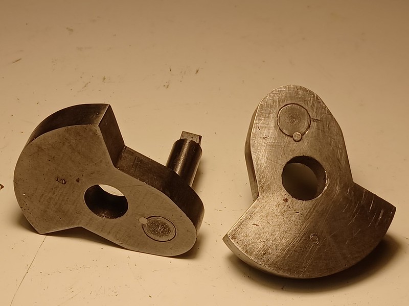 20220618_185440 20220618_185440 by malcolm brown, on Flickr By close of play today, I had also fitted all the LHS fly cranks to their axles with Loctite. Unlike on the prototype (at least as it now is) my fly crank weights coincide with the balance weights on the wheels! Tomorrow, I hope to use the quartering jig to fit the RHS flay cranks - and then the loco can be wheeled properly. Best wishes Malcolm
|
|
mbrown
Elder Statesman
  
Posts: 1,790
|
Post by mbrown on Jun 19, 2022 17:23:48 GMT
Quartering the cranks and wheeling the chassisThe crankpin quartering jig, shown in an earlier post, needed a bit of modification as the pressure from the screws locating in the axle centres was pushing the vertical jig faces out from the vertical. A length of aluminium angle, as seen below, dealt with that. Another design oversight was that the jig needs dismantling to release the axle, wheels and cranks once they are fixed. But that only takes a few minutes. Here's the driving axle sitting in the jig after the second fly crank has been Loctited in place.  20220619_145827 20220619_145827 by malcolm brown, on Flickr All four axles were dealt with, then one crank on each axle was pinned to prevent anything moving of the Loctite failed. The line of the pin is shown in blue marker below - this should give the optimal security. You can just see the end of the 1/8" pin through the fly crank where it has been dressed off. I am not going to pin the other side until I am sure that everything rotates smoothly once the rods are made and fitted - just in case there is some slight error in quartering.  20220619_153810 20220619_153810 by malcolm brown, on Flickr With the axleboxes re-fitted to the wheel sets, the chassis could, at last, be wheeled properly and the horn keeps fitted. So, that's another small milestone passed. With the chassis in one piece and capable of being lifted and moved without the wheels or anything else falling off, I can put it aside for a bit and get on with something else. I have the materials to tackle a number of different jobs next, so it is all down to how I am feeling next time I am in the workshop. 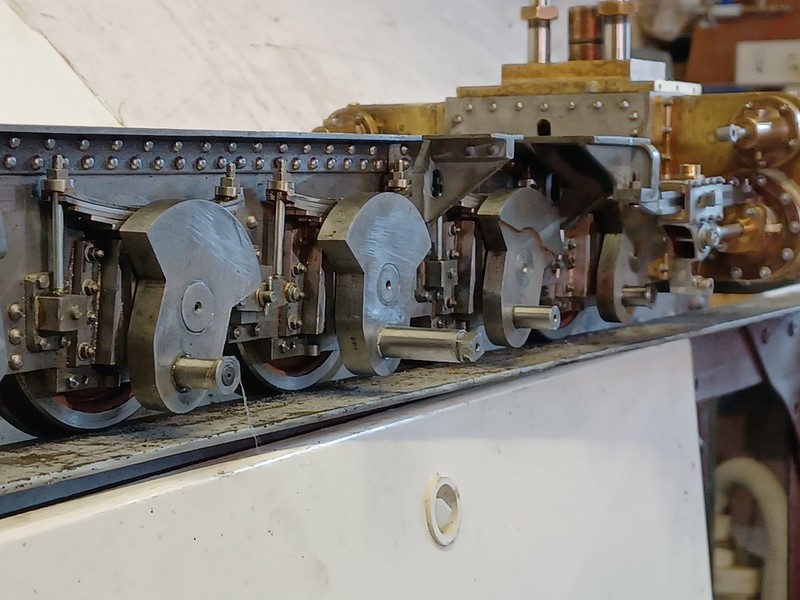 20220619_173903 20220619_173903 by malcolm brown, on Flickr The weight is beginning to mount up, even without the boiler and smokebox. I need to resurrect the rotating building stand I made for the Burma Mines loco (out of two old screw-type car jacks....) but the arrangement for attaching the loco will have to be altered as the buffers and buffer beams are rather different. Best wishes Malcolm
|
|
mbrown
Elder Statesman
  
Posts: 1,790
|
Post by mbrown on Jun 26, 2022 17:37:01 GMT
Connecting the pump.There hasn't been much workshop time this weekend, but I have managed to connect the axle pump to its eccentric, both of which had been made earlier. Because the axles are so close, and because I wanted to reproduce the complex staying between the frames, the only place for the pump was under the smokebox. This is not ideal, as it is driven through two sets of coupling rods, but it is not a big pump - just enough, I hope, to maintain water level with the injector as back up. In terms of accessibility it is not too bad . The eccentric strap is the pump strap casting from the 3.5"g Tich - which has the advantage that the bolting flanges are at an angle and this will allow me to take down the eccentric from below. The small end, however, is completely inaccessible when the loco is on its wheels so lubrication is a problem. I have tentatively managed that by fitting a small (1/8" bore) ball race in the end of the rod. I am not sure how it will stand up to push and pull motion as well as a few degree of rotation, but if it doesn't work I can replace it with a bronze bearing and try to devise some way of getting an odd drop of oil to it.  20220626_163201 20220626_163201 by malcolm brown, on Flickr Here is a view of it assembled, looking from beneath. The lower horizontal stay has been removed - and is removable precisely so that things around the front end can be got at. With the loco inverted, the eccentric strap can be dismantled easily.  20220626_163642 20220626_163642 by malcolm brown, on Flickr And here it is from above, with the platework which goes right across the top of the frames, lodged in place. There is a kind of manhole over each axle, and with the front one removed, the oil pot for the eccentric is easily accessible.  20220626_163751 20220626_163751 by malcolm brown, on Flickr I am away for the next few weekends, so normal service should be resumed in a few weeks time. Best wishes Malcolm
|
|
mbrown
Elder Statesman
  
Posts: 1,790
|
Post by mbrown on Jul 23, 2022 18:32:47 GMT
Back in the Workshop....
After several weekends working at the day job, last weekend was far too hot to do anything active. My workshop is an uninsulated garage, so extremes of cold and heat make is uninhabitable. I am thinking that, before I retire, I need to do something about that...
But today I managed a couple of hours, wasting some of the time wondering what to tackle next. Various options suggested themselves but, as I had made the brake blocks for the loco some time ago, I decided to do the rest of the brake gear.
I didn't take any photos today -- they wouldn't have been very interesting as much of the brake gear is, exactly as on the prototype, made from lengths of steel strip with holes in them.... The brakes are only fitted to the first and third pairs of driving wheels - frame stretchers occupy the equivalent areas ahead of the second and fourth axles -- but the two sets are equalised, which will make adjustment easier.
By close of play today, I had made the brake hangers and brake beams and made a start on the equaliser links. With luck, tomorrow I will manage the pull rods and forks - and will remember my camera to add some pix to the next update.
Best wishes
Malcolm
|
|
|
|
Post by springcrocus on Jul 23, 2022 21:08:50 GMT
Back in the Workshop....I didn't take any photos today -- they wouldn't have been very interesting as much of the brake gear is, exactly as on the prototype, made from lengths of steel strip with holes in them.... The brakes are only fitted to the first and third pairs of driving wheels - frame stretchers occupy the equivalent areas ahead of the second and fourth axles -- but the two sets are equalised, which will make adjustment easier. Best wishes Malcolm I know the feeling! There comes a point in every build where, suddenly, the way forward seems a little hazy. Mundane jobs need to be done in order to progress but they are not worth trying to photograph or write about. Invariably, they are the bits and pieces that bring the neccessary detail to a model but are very hard to define as a separate topic or it's just a case of assembly and test. Either way, sometimes it's easier to just move on and get something built, then do an overview update before the next larger sub-topic. Looking forward to your next update.
Regards, Steve
|
|
mbrown
Elder Statesman
  
Posts: 1,790
|
Post by mbrown on Jul 30, 2022 21:04:42 GMT
Brake RiggingToday I finished the brake rigging on the loco. I didn't take any shots of the manufacturing of parts as they were all very straightforward - lengths of steel strip with holes in them, bits of rod with threads at the ends and some forks from 1/4" square steel. The pins are 1/8" rivets with the heads turned into flat pans and 1/32" split-pin holes drilled through the ends using a simple jig. The rigging is compensated between the two braked axles, which means that adjustment for equal pressure on all four wheel is automatic. The turnbuckles are unlikely to be used in practice as the blocks shouldn't wear much if at all. But they are there on the real loco so I have reproduced them. The rear pull rod is about 5/32" dia and, as I had both RH and LH threading gear for 3 BA, the turnbuckle works as it should. The front pull rod is 1/8" dia (to scale) and I only have RH 5 BA threading gear, so for adjustment one much take the pin out of the front brake beam and rotate the front part of the rod. But that is no real hardship. Here is a general view of the gear: 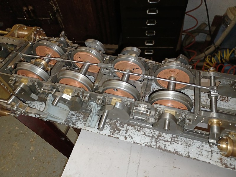 20220730_213013 20220730_213013 by malcolm brown, on Flickr I worked out the layout of the brake gear from my sketches whilst (briefly) underneath the loco back in June 2019, and also from two pictures found on the internet - one of them is a screen grab from a video. I tried - not very successfully - to reproduce these shots on the model, and here they are for whatever interest they may possess. First, looking backward from under the front buffer beam. Because I assembled the gear while the chassis was upside down, I have arranged it all back to front (Left for Right), but that can be put right tomorrow....  49616191_159657471697228_7250616215692458012_n 49616191_159657471697228_7250616215692458012_n by malcolm brown, on Flickr 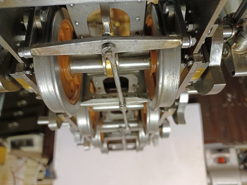 20220730_214052 20220730_214052 by malcolm brown, on Flickr Then looking rearwards from under the ashpan.... 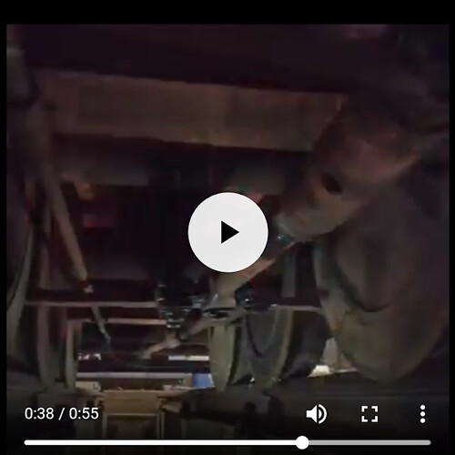 Screenshot_20190413-114354 Screenshot_20190413-114354 by malcolm brown, on Flickr  20220730_213915 20220730_213915 by malcolm brown, on Flickr The split pins on the model haven't been trimmed back yet - I need to do that as I speared myself a few times on them! Best wishes Malcolm
|
|
mbrown
Elder Statesman
  
Posts: 1,790
|
Post by mbrown on Jul 31, 2022 17:32:57 GMT
Through the Looking Glass...
As noted above, I was assembling the brake gear with the chassis upside down - and, because my mind wasn't quite in gear, installed it in mirror image to the way it is assembled on the prototype.
But having taken it all apart again today, I realised that the crank on the brake shaft, which is asymmetrically mounted to suit the angle of the pull rods, can't be turned left for right as the hole for the taper pin won't line up. I don't want to put in a new hole and pin for fear of weakening the fixing.
So it all had to go back the "wrong" way around - but as it is completely invisible when the loco is right way up, it hardly matters. Indeed, although the parts of the rigging are almost certainly original, I can't say for sure which way around they was arranged in the pre-preservation period which I am trying to reproduce.
That's my story and I am sticking to it....
So, having reassembled it all, I spent the rest of the afternoon on boring but necessary jobs like turning up the pins for the loco-tender coupling and trying to work out why the loco is slightly down on its right hand side while the tender is down on the left. All jobs to be finished another day.
Malcolm
|
|
mbrown
Elder Statesman
  
Posts: 1,790
|
Post by mbrown on Aug 7, 2022 21:23:17 GMT
Boiler Certificated....
At the 2.5" Gauge Rally at Little Hay today, I got the boiler for 99 3462 officially tested and certificated.
The rally was a great event - I have posted separately on it under "What I did today". But with the boiler officially tested, I can now get on with fitting it out.
Off to the Talyllyn for a few weeks driving on Tuesday, so no more posts for a while - and when I am back in the workshop, I shall have to think what to make next...
Best wishes
Malcolm
|
|
mbrown
Elder Statesman
  
Posts: 1,790
|
Post by mbrown on Sept 4, 2022 17:06:46 GMT
Starting the rodsAfter a few weeks away and no workshop time for even longer, I am still pondering what to tackle next. But making a start on the coupling and connecting rods seemed like a good idea, despite the amount of work involved with the ten wedge-adjusted brasses. The rods have been laser cut to outline, but still need finishing to thickness. So in an odd hour today I have made up the fixture for this job. It is a piece of substantial steel box section bolted to the mill table and with 2 BA holes at intervals on both the front and top face, to take the rods. Here it is being clocked up: 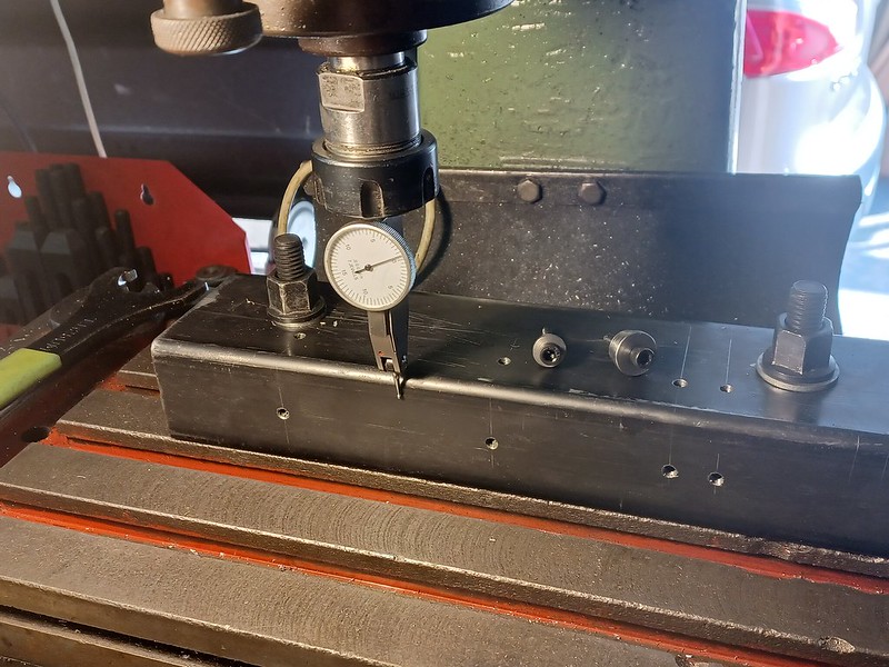 20220904_165534 20220904_165534 by malcolm brown, on Flickr Lying on top, but not very visible, are two of the stepped bushes that are a close fit in the square openings in the rods which take the brasses. These bushes will hold the rod horizontal and prevent it shifting under the milling forces. Here is the centre coupling rod section, as it now stands, attached to the fixture. It can be thinned down with the side of an end mill - and then, for sections where there is no radius, it can be transferred to the top of the box section to use the end of the cutter. 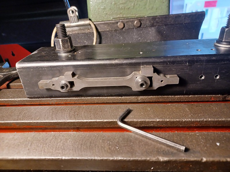 20220904_170411 20220904_170411 by malcolm brown, on Flickr Not much progress, but the psychological start that should get me motivated to complete the rods! Best wishes Malcolm
|
|
mbrown
Elder Statesman
  
Posts: 1,790
|
Post by mbrown on Sept 20, 2022 9:19:46 GMT
I haven't had much workshop time lately, but yesterday I made a start on profiling the rods.
The intermediate rods, shown in the post above, went well so next I tried the connecting rods. Again, all fine until I came to the fluting for which I used a Woodruffe cutter, pivoting the rod from the small end to get the tapered flute.
But the flute, for some reason, was not quite central to the rod - not much but enough for the eye to register the discrepancy. So I tried taking a little more off the larger side - and overdid it. On to the second rod and all was going well when one end of the rod slipped a little and I got a nasty dig in which gouged one of the ribs.
Never mind, each rod has two sides so maybe I could get away with putting the flawed flutes on the inside where no one would notice.... No such luck. Both damaged sides were on the left, so no way could I get a handed pair to look good.
There's a moral here about (a) securing the work and (b) sequencing operations to get the best chance of success.
Anyway, I have ordered another pair of blanks from Ed at MEL.
No pictures of the disasters. I'll take some when I get a better result.
Best wishes
Malcolm
|
|
Gary L
Elder Statesman
  
Posts: 1,208
|
Post by Gary L on Sept 20, 2022 22:50:00 GMT
Bad luck Malcolm, but we’ve all been there!
Gary
|
|
dalboy
E-xcellent poster
  
Posts: 235
|
Post by dalboy on Sept 21, 2022 8:24:26 GMT
I haven't had much workshop time lately, but yesterday I made a start on profiling the rods. The intermediate rods, shown in the post above, went well so next I tried the connecting rods. Again, all fine until I came to the fluting for which I used a Woodruffe cutter, pivoting the rod from the small end to get the tapered flute. But the flute, for some reason, was not quite central to the rod - not much but enough for the eye to register the discrepancy. So I tried taking a little more off the larger side - and overdid it. On to the second rod and all was going well when one end of the rod slipped a little and I got a nasty dig in which gouged one of the ribs. Never mind, each rod has two sides so maybe I could get away with putting the flawed flutes on the inside where no one would notice.... No such luck. Both damaged sides were on the left, so no way could I get a handed pair to look good. There's a moral here about (a) securing the work and (b) sequencing operations to get the best chance of success. Anyway, I have ordered another pair of blanks from Ed at MEL. No pictures of the disasters. I'll take some when I get a better result. Best wishes Malcolm I know the feeling I have remade one of my rods twice and still need to do it again. I have solved the problem like yourself, as you say "(a) securing the work and (b) sequencing operations to get the best chance of success." |
|
mbrown
Elder Statesman
  
Posts: 1,790
|
Post by mbrown on Sept 25, 2022 18:11:27 GMT
Side rodsAfter making a mess of the fluted connecting rods, I have had a bit more success with the side rods. They aren't fluted, but getting the alignments right was interesting as the sides are relieved so as to offset the bearings slightly and give clearances at the front crankpin. Each section is different in that respect. The long slots in the end sections were too deep to use a slitting saw (or rather, I didn't have a suitable one) so they were done with a 4 mm slot drill, slowly! The laser cut blanks needed a lot of cleaning up on the cut edges and the hardened surface had to be broken through with a diamond file before using a normal file to clean up. Here they are, although there is an awful lot of work still to do - including the brasses and adjusting wedges, the oil boxes and covers and the bushes for the articulated sections.  20220925_165613 20220925_165613 by malcolm brown, on Flickr At the moment they have been tidied up and the milling marks removed by draw filing, first with a fine file, then with an ultra-fine Swiss file. They will eventually be finished my usual way - with a piece of fine emery cloth wrapped round a piece of 1/4" BMS bar in the drill press and the rod touched against it. I find it much easier to get a good finish this way than using a sanding drum in the Dremel. But that will have to wait until all the rest of the work is done. Here is a repeated photo of the bearing on the second axle of the prototype. 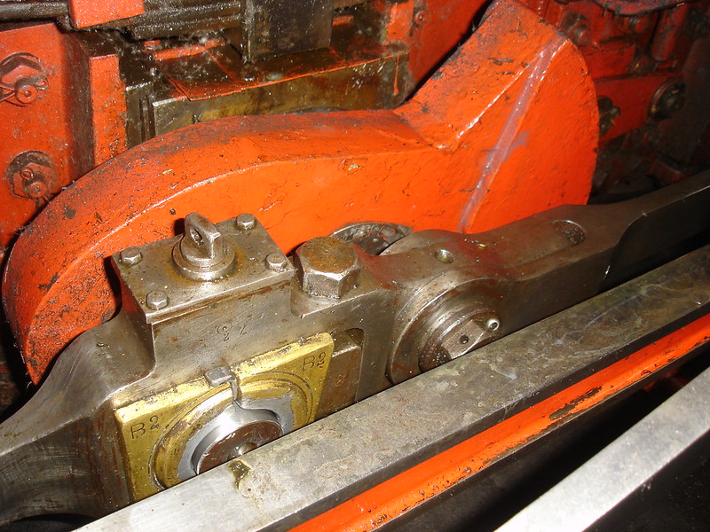 DSC00441 DSC00441 by malcolm brown, on Flickr Best wishes Malcolm
|
|
|
|
Post by ettingtonliam on Sept 26, 2022 13:03:04 GMT
At least those adjuster wedges will be easier to make than gib and taper cotter adjusters. I had to faff around with 12 of those for Locomotion, and was mighty glad when I'd finished them!
|
|
mbrown
Elder Statesman
  
Posts: 1,790
|
Post by mbrown on Sept 26, 2022 13:12:57 GMT
Thanks Richard - I think I am reassured by that as I have made several gib and cotter big ends. On the other hand, getting the wedges and adjusting screw to fit snugly may be "interesting". I need to make a fixture to ensure that the angle on each wedge and each brass is identical every time.
Malcolm
|
|
mbrown
Elder Statesman
  
Posts: 1,790
|
Post by mbrown on Oct 30, 2022 18:27:53 GMT
Connecting RodsVarious circumstances have conspired to keep me out of the workshop for several weeks - the demands of the day job, some driving on the Talyllyn, a nasty bout of Covid despite having all the jabs (variety is the spice of life!). But I managed to return today and have made some progress with the connecting rods. First time around, I messed up the fluting. I found it hard to get the flanges at top and bottom the same depth. This is much easier now that I have replaced a broken return spring on the quill of my milling machine which makes for much more sensitive feed on the Z axis. Anyway, having got replacement blanks from Ed at MES, and tidied up the profile, the fluting went according to plan this time. Here is one of the rods with the Woodruffe cutter just taking out the middle of the flute, having cut the two edges.  20221030_151209 20221030_151209 by malcolm brown, on Flickr The rod is mounted on the piece of rectangular steel tube already shown in a post above. By fixing the rod to the same holes, and using the stops on the mill table, I could get the ends of the flute to line up nicely at each cut. I haven't yet started the main bearing brasses and their adjusting wedges. But I had been puzzling how to do the oil boxes on the top of each bearing. As the photo of the prototype shows in the post above, these are covered by a thin steel plate held by four very small screws in the corners. I reckoned that the screws would be much too small to reproduce, but I wanted the effect of the plate and a substantial oil reservoir underneath it. The solution was to tap a 1/4" x 40 hole in the top of the rod and to turn up a kind of button with a short matching thread. This was then reversed and faced down until the flange (3/4" dia) was 1/32" thick. It was then screwed hard into the rod, and the edges were then filed down until almost flush with the edges of the oil box. If it moves later, a drop of nut lock Loctite should hold it all in alignment. Here are two shots showing each side of the "lid" before fitting and shaping.  20221030_170332 20221030_170332 by malcolm brown, on Flickr  20221030_170424 20221030_170424 by malcolm brown, on Flickr The top side has a small (3mm dia) pip, drilled so that oil can be fed to the reservoir. The prototype has screwed caps to each of these oiling points, but I felt that was a step too far as the cap would be like a tiny 8 BA screw and so easily lost, not to mention inaccessible to unscrew. And here are the rods with the oil box tops shaped to suit. The little ends have bronze bushes, and a small slot is also milled in the side of the rod to take a piece of bronze shim which represents the adjustable small end bearing in full size, with the horizontal adjusting screw and nuts. As the small end bearing is inside the crosshead, the effect should be realistic. The rods still need finishing with fine emery sticks. The fluting is a little uneven. although the light exaggerates that, but some work with small riffler files should get rid of the blemishes. In any case, the flute itself will be painted red eventually.  20221030_174839 20221030_174839 by malcolm brown, on Flickr Next job, the bearing brasses... and then only another 8 oil caps, bearings and wedges to do on the coupling rods.... Best wishes Malcolm
|
|
mbrown
Elder Statesman
  
Posts: 1,790
|
Post by mbrown on Nov 5, 2022 19:41:57 GMT
Big end brassesOn with the big ends today. The only bronze I had that would clean up to the right size was length of 7/8" bar so, with that on the rotary table, it was straightforward to mill a rectangle to the right size and then clean up two sides to just not fit in the opening in the rod. It rather resembled a Guage 1 axlebox at this stage - and then was parted off in the lathe. 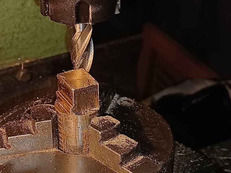 20221105_155140 20221105_155140 by malcolm brown, on Flickr Then, using the vertical slide, the slot that engages with the rear of the rod opening was put in. This is the only edge of the bearing that is flanged on both sides.  20221105_160921 20221105_160921 by malcolm brown, on Flickr To ensure that the angle on the brasses and on the wedges is identical, I made a simple template from 4 mm BMS. This sits in the machine vice on the mill and by holding the workpiece against it, the angle is generated automatically.  20221105_181715 20221105_181715 by malcolm brown, on Flickr I didn't take a pictures of this operation on the fourth side of the brass. The brass was then carefully fitted to the rod, the position of the big end bore established with a trammel from the small end and centre popped, then set up in the four-jaw on the lathe to drill and bore the hole for the crankpin. Again, I neglected to take pictures... too absorbed in the job! The wedges were machine up from some 5/16" square bar. It took a while to fit them to the big ends as the wedging action means the vertical movement is a lot more than the horizontal, so getting the length right took a while. I then drilled one rod for the adjusting screw which will be a 7 BA hex screw running right through the rod and the wedge. Unfortunately, after taking great pains to tap the hole in the edge carefully, I managed to break my one and only 7 BA tap just as it was emerging from the hole which is about 3/8" long. So that put an end to operations for a while until the new taps I have ordered arrive. Then I will also have to re-make that wedge as there is no way I can get the broken tap out of it. Anyway, here are the rods with their big ends and wedges and just awaiting the adjusting screws.... The brass in the rod nearest the camera is not sitting quite flat so I will have to investigate why in due course. 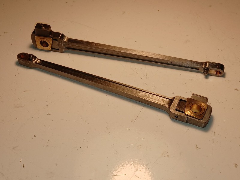 20221105_181801 20221105_181801 by malcolm brown, on Flickr Best wishes Malcolm
|
|
|
|
Post by springcrocus on Nov 5, 2022 21:50:20 GMT
Big end brassesOn with the big ends today. .... The brass in the rod nearest the camera is not sitting quite flat so I will have to investigate why in due course. Malcolm Malcolm,
Because you barely had half of the workpiece in the jaws of the vice, it's possible that the jaws lifted a little. That would cause this sort of error.
Regards, Steve
|
|
mbrown
Elder Statesman
  
Posts: 1,790
|
Post by mbrown on Nov 5, 2022 21:56:12 GMT
Thanks Steve - but I don't think it is that as all the faces of the brass are parallel to each other. I only noticed it when I saw the photo and haven't gone back to check, but it may be that the wedge, which is not tight in the picture, is sitting out of line and pushing the brass up. I will look at it when next in the workshop....
Malcolm
|
|
mbrown
Elder Statesman
  
Posts: 1,790
|
Post by mbrown on Nov 12, 2022 19:33:22 GMT
Big Ends completedA new set of 7 BA taps arrived during the week, so today it was back to the big end wedges. For what is, essentially, a little block of 5/16" thick BMS, each wedge was a lot of work and several scrap ones now litter the bench. Apart from the one with the broken tap in it from last weekend, the problem is that getting the wedge to sit tightly about half way up its travel means that even a tiny bit too much metal removed and it no longer locks the brass in place. But I think I am getting the hang of it... Here they are with the wedges and adjusting screws in place. 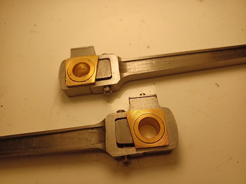 20221112_174244 20221112_174244 by malcolm brown, on Flickr The brass that was a wee bit askew in last week's photo now sits squarely in the rod. The problem was a tiny burr on the inside of the rod which just prevented the brass seating firmly on its back edge. They seem nicely tight, but when I assemble these rod ends permanently I think I will add a smear of low-strength Loctite just to keep everything from vibrating loose. Only eight more of the little beggars to do still. Plus the oil boxes on each coupling rod bearing and the pivot pins between the three sections of each coupling rod. So getting all the rods to the final state will take a while yet. Until the 1960s, 99 3462 even had adjustable wedged bearings on the eccentric rods - about 1/4 the size of the big ends. Fortunately for me, by the period I am modelling these had been changed for solid bushed bearings! Best wishes Malcolm
|
|
 20220618_180958 by malcolm brown, on Flickr
 20220618_181302 by malcolm brown, on Flickr
 20220618_185440 by malcolm brown, on Flickr
 20220618_180958 by malcolm brown, on Flickr
 20220618_181302 by malcolm brown, on Flickr
 20220618_185440 by malcolm brown, on Flickr


