|
|
Post by springcrocus on Dec 31, 2022 8:13:36 GMT
First-class piece of work. I'm envious of your ability to work on something so small and achieve that level of detail.
Regards, Steve
|
|
|
|
Post by simplyloco on Dec 31, 2022 8:58:35 GMT
Great attention to detail. I've never made a tap in my life, and that is a good job!
John
|
|
mbrown
Elder Statesman
  
Posts: 1,790
|
Post by mbrown on Jan 27, 2023 20:18:37 GMT
This Thread
I haven't been able to get into the workshop since New Year for the simple reason that I did a big clear-out which showed that the floor needed resealing. I got everything lined up to do this when the temperatures dropped too far for the sealer to set - and I can't afford to keep the heat on for that long!
I have been following the correspondence about the future of this forum - with a degree of sadness at the apparent loss of some excellent people and inspiring threads. So below, please see my own "Terms and Conditions" regarding this thread....
1. I don't care where it sits within the forum structure so long as I can find it again!
2. I do the posts partly in the hope that they may amuse or inform others, but mainly so that I have my own record of all the trials and tribulations for future reference. So I shall go on posting until either the loco or I are finished - whichever is the sooner.
3. Anyone is welcome to add to the thread, whether with a simple "Like" or with comment, criticism, suggestions, warnings ... whatever. The more the merrier. I don't care if they are not strictly relevant. The main thing is the interaction with other minds.
4. I will endeavour to respond from time to time to other threads which I follow in the hope that this is encouraging to the thread-owner... I get more enjoyment from some of the other threads here than from doing my own.
I guess others will have a different approach, but those four points sum up my philosophy for being here at all.
Best wishes to all.
Malcolm
|
|
|
|
Post by simon6200 on Jan 27, 2023 20:23:59 GMT
Well said Malcolm.
|
|
|
|
Post by coniston on Jan 31, 2023 20:46:02 GMT
Agreed Malcolm, I'm following your build with interest.
Chris
|
|
mbrown
Elder Statesman
  
Posts: 1,790
|
Post by mbrown on Feb 4, 2023 18:16:05 GMT
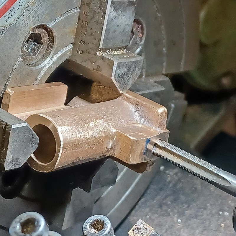
Hand PumpI decided to leave the workshop floor until the temperature is steadier. Meanwhile, I am spoilt for choice as to the next thing to do.... I have been thinking out the tender body, so I thought a simple project for today would be the handpump. I was thinking of fabricating it, but would have had to buy the bronze, and factoring in the cost of silver solder, buying a casting wasn't much more expensive and saved a fair bit of time. I like the Don Young handpump design and used it before on the Burma Mines loco. It can be bored and reamed right through and, if necessary, is easy to attach to a bulkhead. I didn't photograph the relatively simple job of machining the bore in the 4-jaw chuck. As you can see, I didn't get the bore absolutely in the centre of the casting, because the chucking piece wasn't as concentric as it looked. Hey ho... Then, in the mill, the various edges were cleaned up.  20230129_172350 20230129_172350 by malcolm brown, on Flickr The body was then re-chucked to drill, D-bit and tap the entry and exit holes. These have ceramic balls fitted.  20230204_142609 20230204_142609 by malcolm brown, on Flickr The ram is 1/2" stainless steel. The end is relieved so that water can find its way past the end of the ram even if it pushed fully home. This is because I intend to draw the supply for the axle pump through the handpump to save one connection between loco and tender, so the flow has to be free. Here, you can also see how the barrel has ports so that the ram doesn't block the inlet and outlet. You can also just make out a 1/16" copper rivet pressed in to act as the stop for the inlet ball. I much prefer this to trying to damage the hole between the ball and the chamber so that the ball doesn't block it when it lifts.  20230204_155842 20230204_155842 by malcolm brown, on Flickr And here is the final product. I hate the usual bit of flattened tube that is often used for an extension handle as it always seems to go floppy after a bit of use. My pumps all have a hole (7/32" dia in this case) for a round extension handle which is a good fit. The links and pins are also beefed up from the Don Young design and there is almost no slop at all from side to side. The inlet is extended a bit as the pump will sit in a ledge in the tender to bring the handle nearer the opening and reduce the amount of swing needed on the handle  20230204_173532 20230204_173532 by malcolm brown, on Flickr Altogether quite a satisfying day's work. Best wishes Malcolm
|
|
|
|
Post by steamer5 on Feb 4, 2023 21:18:38 GMT
Nice work Malcolm,
Quick question have you drilled a hole at the bottom of the handle hole at 90 degrees to the lever hole?
When I got my loco every time I used the handle I got a squirt, worse when the tank level was low, a 2 mm, from memory, gave the water in the handle hole somewhere to go, rather than the eye!
Cheers Kerrin
|
|
mbrown
Elder Statesman
  
Posts: 1,790
|
Post by mbrown on Feb 4, 2023 22:05:46 GMT
That's a great idea Kerrin! In fact, the stainless pin for the middle pivot cuts through the vertical hole for the handle. But as the pin is a good fit, that might not be enough to prevent the squirt....I shall have to experiment.
Malcolm
|
|
mbrown
Elder Statesman
  
Posts: 1,790
|
Post by mbrown on Feb 5, 2023 18:20:51 GMT
|
|
|
|
Post by ettingtonliam on Feb 6, 2023 0:06:20 GMT
Mines the other way up, with the hollow section on the bottom of the removeable extension. Doesn't seem to give rise to trapped water problems.
|
|
mbrown
Elder Statesman
  
Posts: 1,790
|
Post by mbrown on Feb 11, 2023 22:21:11 GMT
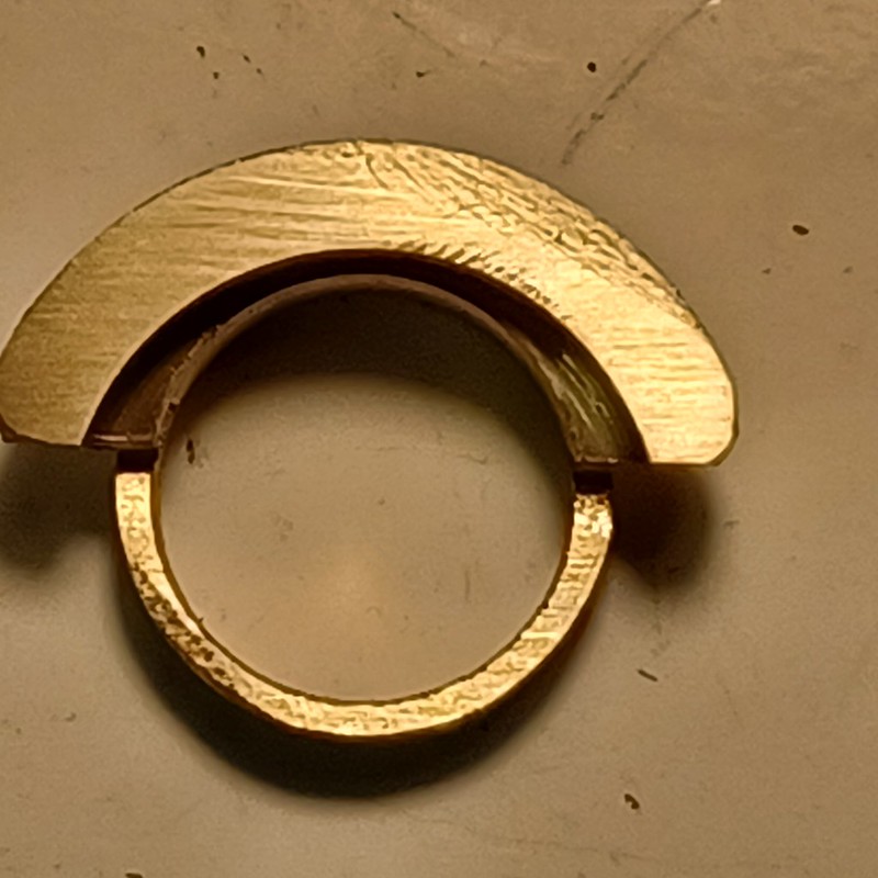
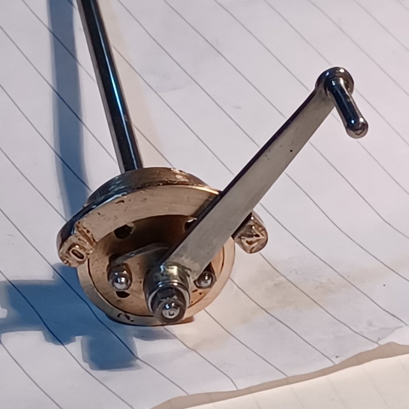
Regulator quadrantThe regulator quadrant on 99 3462 is shown below - with the standard German letters O and Z for Open and Shut (not sure of the exact words in German...). The quadrant is also on a wider radius than the gland housing - that is, they are not concentric. I have been thinking out how to make this for some time... Here it is in full size.  40540771_291950111595205_7859561320117436416_n 40540771_291950111595205_7859561320117436416_n by malcolm brown, on Flickr I started with a piece of gunmetal bushing which I bored and turned to make a sleeve to go over the backhead bush and turned an outer collar with the sleeve offset in the 4 jaw chuck. Then a bit of judicious work with a hacksaw and files, gave me the basic shape as below. I am afraid that the eccentric turning process was rather absorbing and I forgot to get the camera out at that stage.  20230211_154941 20230211_154941 by malcolm brown, on Flickr Further work, partly on the mill and partly with files, gave me the stand-out quadrant - and here it is, mounted on the boss which is screwed to the backhead bush on four 8 BA studs. This now has its oval gland.  20230211_173735 20230211_173735 by malcolm brown, on Flickr For reference, the overall diameter is 3/4". I have had various ideas about how to reproduce the raised letters on the stops. I wondered about sweating on the pattern-makers' embossed letters that Reeves sell - but the smallest, at 3/16" high is too big. I need letters about 3 mm high. I thought of making my own raised letters with a punch on a bit of brass shim - but although my 3 mm letter punches will do a fine O, the Z comes out back to front.... So my plan is to mask off all the quadrant except the raised stops, put the letters on with Letraset (if I can find any in my collection of old sheets) and etch them in ferric chloride. I may have time to try this method tomorrow and will report if it works (or not!) Best wishes Malcolm
|
|
|
|
Post by brucevoelkerding on Feb 11, 2023 22:34:31 GMT
O = offen English "open"
Z = zu English "closed"
but, remember to pronounce "zu" as "tsu" - not like English "zoo"!
|
|
mbrown
Elder Statesman
  
Posts: 1,790
|
Post by mbrown on Feb 11, 2023 22:48:57 GMT
I knew someone on the forum would know! Thank you very much.
Malcolm
|
|
twombo
Seasoned Member

Posts: 120 
|
Post by twombo on Feb 13, 2023 7:55:44 GMT
Jawohl Mein Herr!, says I, to Der Burgermeister! Very neatly done Malcolm! It is a pleasure following your work! I'm afraid, I'm more of the "Bear Cub" in a china Shoppe"! My best is a simple PB thrust washer to .020" thickness. Truly, luck, More than Anything else! Thank you for the 'Lessons!
|
|
|
|
Post by ianholder on Feb 13, 2023 10:25:37 GMT
Are you sure that its not the angle of the photo that makes it look as if its not concentric? Don't make another one though, I'm probably wrong! regards Ian
|
|
mbrown
Elder Statesman
  
Posts: 1,790
|
Post by mbrown on Feb 13, 2023 10:58:27 GMT
Hi Ian,
I chose the photo because it shows the lettering on the stops - you are right that the eccentricity of the quadrant isn't so obvious in that shot. I don't have a better photo but the different curvatures are quite obvious "in the flesh", so to speak. If anything, I haven't made the difference quite as big as it should be.
Best wishes
Malcolm
|
|
mbrown
Elder Statesman
  
Posts: 1,790
|
Post by mbrown on Feb 13, 2023 21:51:23 GMT
Regulator quadrant and leverEtching the raised letters on the quadrant stop took longer than I anticipated, but they came out OK. I used 3 mm high Letraset and masked all the rest of the piece with paint (one way to use up an old can of Humbrol). It was immersed in a solution of Ferric Chloride - about half and half with water - and kept warm on a radiator. The piece was balanced on a lump of plastic which allowed the quadrant itself to hang downwards clear of the bottom of the glass container, so that any products of the etching would fall away cleanly. I had expected it to get to a reasonable depth in a couple of hours, but after that time the letter was only just beginning to show in relief. Rather than leave it overnight and risk going too deep and risk undercutting, I took it out overnight and re-immersed it this morning. By about lunchtime I reckoned I had a reasonable depth of etch, so I washed it off, removed the paint in cellulose thinners and polished it up. The area around the letters has an etched finish which gives a good impression of a cast surface.  20230213_213515 20230213_213515 by malcolm brown, on Flickr While the quadrant was etching yesterday, I made the regulator handle. The one on 99 3462 in preservation appears to be nickel (?) plated - certainly the main levers on some of the other WEM locos are plated, possibly in chrome which, to my mind, doesn't look appropriate at all. I reckoned that (a) the regulator probably wasn't plated in MPSB/DR days and (b) that bright stainless steel should look the part and not discolour in service. Dimensions were taken from the prototype on my visit but I have been a bit generous to the tune of 0.5 mm here and there in the interests of robustness - it is only 1/16" thick material. Anyway, another little part completed and, IMHO, looking the part. Best wishes Malcolm |
|
mbrown
Elder Statesman
  
Posts: 1,790
|
Post by mbrown on Feb 18, 2023 20:56:50 GMT
Fitting the regulator(Almost 24 hrs since the last post on the forum... where is everybody?) I made the regulator, to the Gordon Smith design, some time ago and now that I have made the backhead flange etc, it seemed like time to complete the steam circuit. Here is the regulator.  IMG_20220403_175018 IMG_20220403_175018 by malcolm brown, on Flickr The plate which sits between the dome flange and the inner dome was designed to carry the regulator - so here it is, opened out to accommodate the regulator which is secured by two small angles fitted with stainless screws. I drilled a matrix of 3/32" holes to ensure that the steam can fill the dome fully, although the larger gap in front of the regulator, which gives access for connecting the regulator operating rod and cam, would probably pass enough anyway. I thought the smaller holes might discourage water lifting as the semi-pop safety valves will be on top of the dome. If I do get water lifting through the larger orifice, I can always screw on a small cover, with or without further small holes.  20230218_174650 20230218_174650 by malcolm brown, on Flickr Tomorrow, all being well, I will connect up the operating rod and make and fit the wet header and superheater elements. Best wishes Malcolm |
|
mbrown
Elder Statesman
  
Posts: 1,790
|
Post by mbrown on Feb 19, 2023 17:51:20 GMT
(Almost) Completing the steam circuitOn with the job this afternoon... I bought a pair of welded stainless superheater elements from Polly some time ago - good job I did, as I don't know if they will continue to supply them now. They are from 1/4" stainless tube and considerably over length for my needs, but that gave plenty to hold onto when bending them. The tube bends very easily when red hot, so I put a length of wider tube over the straight part of the element, heated the required area to bright red, and with a gauntlet on the other hand, bent the element around to a fairly tight right angle. Here's the result.  20230219_135338 20230219_135338 by malcolm brown, on Flickr Next up was the wet header. This slips over the main steam pipe emerging from the regulator, and sits inside the recess in the bush on the tube plate. An O ring seals it to the steam pipe and the bush and the whole lot is tightened down with a strong-back held by two 3/16" studs and nuts. Here's the wet header - the connection in the middle is for the snifting valve. I didn't make this quite long enough so I had to cut a slight recess in the strong back to allow the union to tighten fully. But it doesn't affect the overall arrangement.  20230219_140324 20230219_140324 by malcolm brown, on Flickr Here are the header and elements erected in the smokebox. On the Burma Mines loco, I bent the stainless elements to connect to the cylinder steam pipe unions, but the stainless tube has almost no "give" in it and it took ages to line them up accurately. So on this loco I will braze on copper extensions which can be bent more easily and flex a little. That's the bit of the steam circuit I have yet to do.  20230219_150200 20230219_150200 by malcolm brown, on Flickr Connecting up the regulator mechanism involved a number of small parts. Here are all the bits set out in order. The cam on the end of the rod is pinned in place with a 1/16" stainless pin. The whole cam can be inserted through the bush on the backhead and the main flange is then bolted up to the backhead and seals with O rings. Nearer the backhead end of the regulator rod is a small collar. This passes through the main flange. Then comes a shouldered collar which sits in the packing space in the flange and just clears the fixed collar, thus preventing the rod moving backwards. The PTFE packing and oval gland follower go in next and hold the shouldered collar against the fixed collar (with a small clearance for any differential expansion). Finally, the stops slide over the flange and are secured with a 6 BA grub screw, and the regulator handle finishes it off.  20230219_160514 20230219_160514 by malcolm brown, on Flickr And here it is from the backhead end with the regulator and fire door erected.  20230219_164052 20230219_164052 by malcolm brown, on Flickr Having replaced the dome cover, I found to my consternation that the regulator wouldn't open fully. It took me a while to realise that, as the regulator opens, the operating rod rises and it was hitting the inside of the inner dome. It took only a few minutes to relieve the inside in the vicinity of the regulator by about 3/32" - it was plenty thick enough as the top of the inner dome is threaded for the safety valves. It does mean that I am collecting steam from the highest possible point. Another step forward. Best wishes Malcolm
|
|
jma1009
Elder Statesman
  
Posts: 5,918
|
Post by jma1009 on Feb 19, 2023 21:11:17 GMT
Hi Malcolm,
Very pleased to see your progress, and although I don’t often comment, always follow this thread with much interest.
Cheers,
Julian
|
|