mbrown
Elder Statesman
  
Posts: 1,793
|
Post by mbrown on Jun 3, 2023 19:46:21 GMT
Dummy Chime WhistleI have been having a rest from the workshop for a few weeks - two weekends were spent at Tywyn driving on the TR, but more importantly, I managed to seal and repaint the floor of the workshop (and the garage) which I hope will keep some of the dust down. The paint took a lot longer to dry than I expected but seems to have set hard and feels durable. I was very careful not to paint myself into a corner - but then found that all my hand tools were on the other side of the wet surface, so even basic jobs had to be put on hold for a while. Anyway, this weekend I went back to 99 3462. The main task was to strip the chassis down (again) as I can't seem to get all eight wheels firmly on the rails at once. That should be straightforward now that I have lifted the boiler, dropped the brake gear, the hornstays, the coupling rods and the spring gear. But meanwhile, I had been thinking out how to do other bits and decided to have a go at the whistle and its valve. This sits on the top of the boiler on top of a long stem with the whistle valve near the top. I have been figuring out how to use that valve to operate large whistle between the frames and blow some steam out of the dummy. Today, I made the dummy whistle itself and made a start on the operating mechanism. The whistle is in two parts - the lower part almost like a wing-valve but with a 1/16" hole through it to take steam. The outer part fits over it and the two are joined with a smidgen of soft solder paste. The whistle overall is just an inch high and 5/16" diameter. 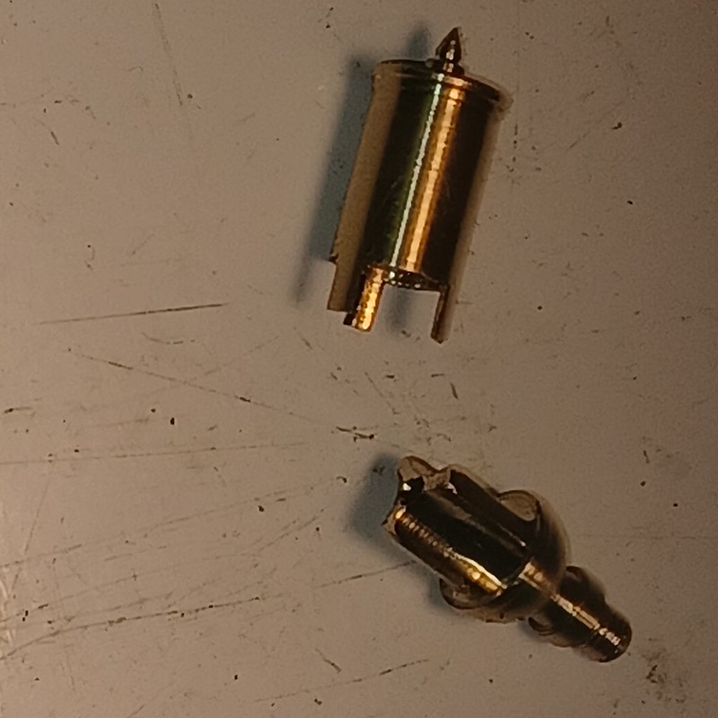 20230603_145327 20230603_145327 by malcolm brown, on Flickr 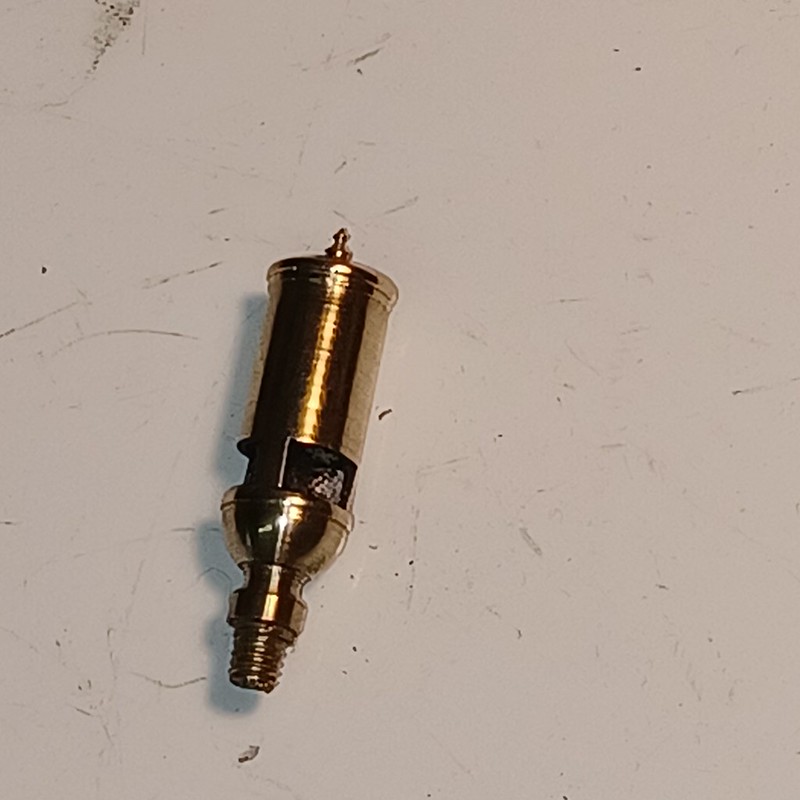 20230603_150903 20230603_150903 by malcolm brown, on Flickr The light doesn't do it any favours - it has actually polished up fine. I may have time to complete the rest tomorrow. Best wishes Malcolm |
|
mbrown
Elder Statesman
  
Posts: 1,793
|
Post by mbrown on Jun 4, 2023 17:38:00 GMT
Whistle valveHere is the completed whistle valve with the dummy whistle. The challenge was to get steam to the large external whistle and a smaller amount to the dummy whistle, all the mechanism being rather prominently visible on top of the boiler. Below are the various parts. The ball seats onto the bottom of the fitting and is supported on a sprung spindle which extends upwards in to the dummy whistle, The top section is a length of 1/16" stainless tube and the lower section is drilled through its length up to a small cross hole just below the brass collar. That is the route for the steam to the dummy whistle. The take- off for the main whistle is obvious - unprototypical, but the boiler is so festooned with pipes and unions that it should blend into the background! 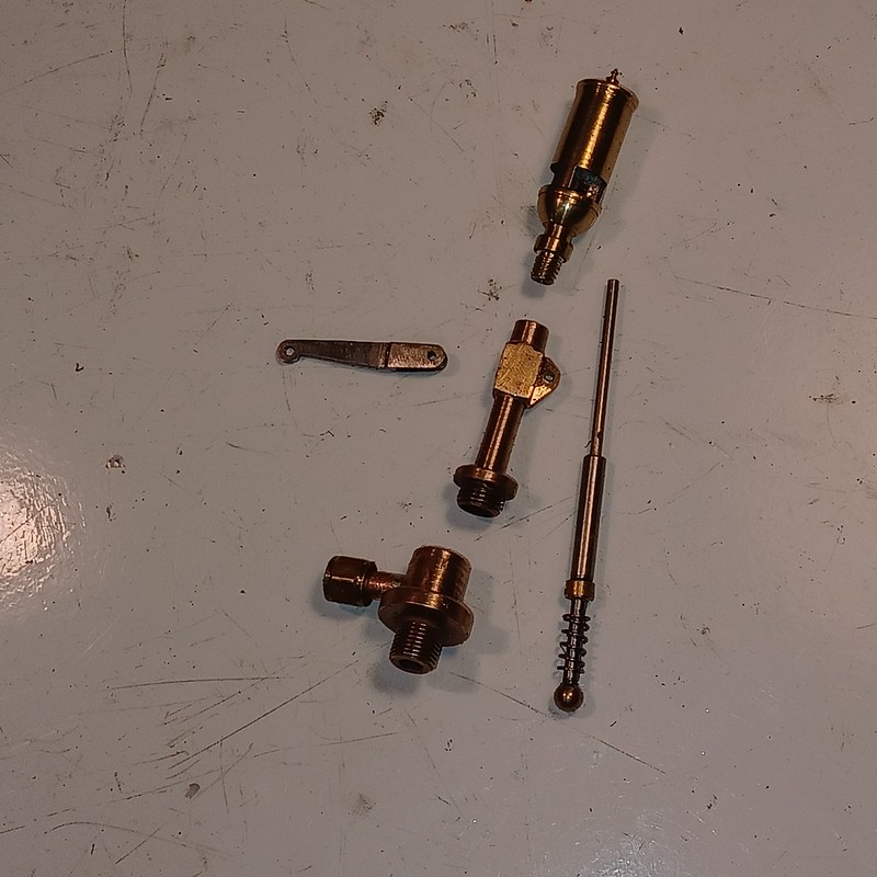 20230604_173749 20230604_173749 by malcolm brown, on Flickr The operating lever is forked and the thin tube passes between the forks. The tricky bit was silver soldering the pivot block onto the column so that the forked lever could still fit either side of it. And here it is assembled. I haven't tried it on steam but it seems to work OK on lung power. 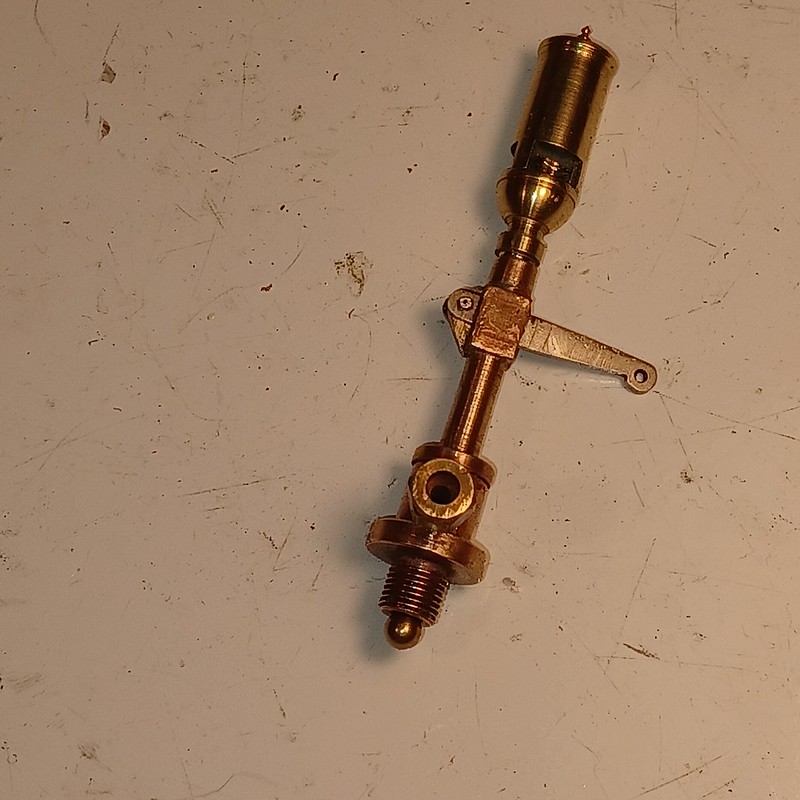 20230604_175015 20230604_175015 by malcolm brown, on Flickr Best wishes Malcolm |
|
mbrown
Elder Statesman
  
Posts: 1,793
|
Post by mbrown on Jun 11, 2023 20:15:50 GMT
Adjusting the springingA couple of hours was all I could manage in the workshop this weekend, but I think I have resolved the springing issue. First task was to set the chassis, upside down and level, on the milling machine table (the lathe bed wasn't big enough) using a pair of 5x3x1 blocks at the front and a suitable bar and shims at the rear. This proved that there was no twist on the chassis. I then used a scribing block, lined up with each axle centre, to set each axle end to the same height by adjusting the nuts on the spring pins. 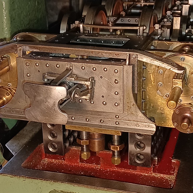 20230611_150119 20230611_150119 by malcolm brown, on Flickr The error had crept in because I hadn't cottoned on to the effect of having the 1st and 2nd, and 3rd and 4th, axles compensated on each side. This had led me to set each axle without reference to its neighbour. But ensuring that all the axles were at the same height at the same time made all the difference. It needed one axlebox to be adjusted by almost 1/16" in height. 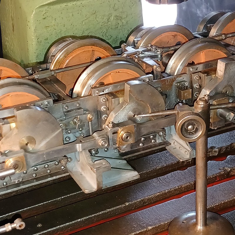 20230611_150136 20230611_150136 by malcolm brown, on Flickr That didn't seem enough, though, to account for the problem as it had first appeared. A great deal of trial and error ensued before I thought to check the building stand on which the loco had been standing when I identified the problem. This was made many years ago from an old angle-iron bedstead cut in half and rearranged with a 2.5" gap between the sides. On checking with a spirit level, the sides were not quite parallel with one corner being down by about 1/16". This, combined with the compensation error, had led to the rear left hand wheel being about 3/32" above the rail when the other wheels were in contact. Problem solved.... It hadn't shown up with my previous locos all of which had much shorter fixed wheelbases. Here's the building stand - if a suitable bedstead ever turns up it would be an easy thing to copy, just using different lengths of set bolts according to gauge. Leaving the spring supports in place gave me a support for the shelf. 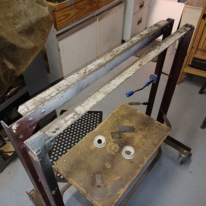 20230611_151017 20230611_151017 by malcolm brown, on Flickr Best wishes Malcolm
|
|
mbrown
Elder Statesman
  
Posts: 1,793
|
Post by mbrown on Jun 17, 2023 18:00:25 GMT
PTFE Piston RingsBefore I can erect the connecting rods, I needed to remove the pistons as the rods are over-length. Once the con rods are on, I can measure the piston rod length and attach them to the crossheads. When I made the cylinders, I used 1/8" section O rings on the pistons, but after reading a number of threads on this forum, I decided something better could be done and settled on PTFE rings with O rings underneath them to give them a bit of spring. I haven't got the right size O rings yet - I will put two 1.5mm section ones side by side under the PTFE ring. But I did have a suitable bit of PTFE so made the split rings. Having turned the outside diameter, I felt it was a bit wasteful boring out to make them 1/16" thickness, so made a small trepanning tool which left me a decent diameter of PTFE bar after the rings had been parted off.  20230617_152615 20230617_152615 by malcolm brown, on Flickr Above is the trepanning tool at work prior to parting off the rings to the correct width. I found the best approach was to part almost all the way through to the trepanned groove, then finish the cut-off with a scalpel held against the side of the parting tool slot. To split the rings, I pushed them onto a suitable brass mandrel and cut a slot down the centre for about 3/8" length. Then cut through the opposite sides and removed about 3/32" from each "ear" that was left. I am hoping this will give steam tightness along with plenty of room for expansion. The picture shows how the ring opened out after cutting 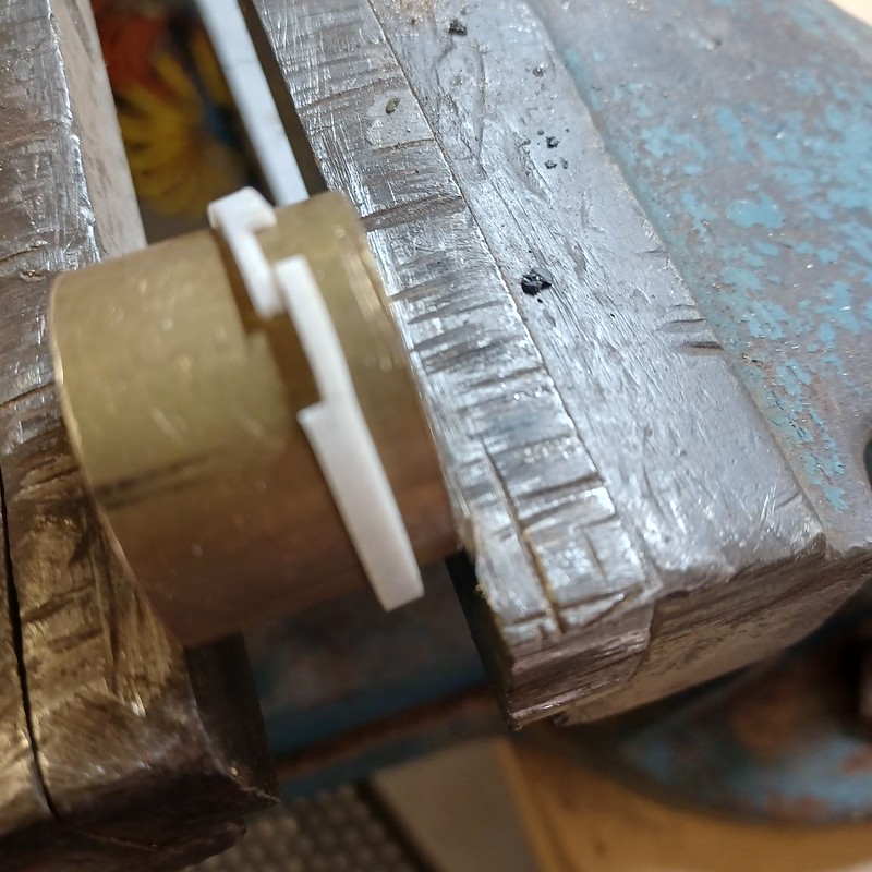 20230617_154500 20230617_154500 by malcolm brown, on Flickr Finally, here is a ring on its piston. By next weekend, I should have the O rings and can test the fit.  20230617_154549 20230617_154549 by malcolm brown, on Flickr After that job, several hours were spent fitting the connecting rods. I found I hadn't allowed quite enough vertical movement for the small end within the cross head so they were binding at top dead centre. I bit of work with a file and with a Dremel and small grind stone has opened out the crosshead pocket and the wheels now go around, albeit stiffly at present. Best wishes Malcolm |
|
mbrown
Elder Statesman
  
Posts: 1,793
|
Post by mbrown on Jun 20, 2023 18:36:26 GMT
Piston rings cont.The O rings arrived today so I took half an hour to fit them under the PTFE rings and try the final combination in the cylinder bores.  20230620_183721 20230620_183721 by malcolm brown, on Flickr They fit OK and slide smoothly although one feels tighter than the other and I wonder if the pair of 1.5mm section O rings are already squeezed down too far. I can always take a skim off the bottom of the groove to give them a little more "movement". But I wondered if anyone has any idea how much the PTFE rings actually expand at superheated steam heat? The rings are 1/8" x 1/16" section. Should I leave a bit of play at the sides of the groove as well as on the diameter? Does the gap look about right? Any wisdom - or practical experience - gratefully received. Best wishes Malcolm
|
|
|
|
Post by Roger on Jun 22, 2023 20:29:02 GMT
Very neat, that's a lot simpler than my setup.
Google says "PTFE has a coefficient of thermal expansion of approximately 151 x 10-6 per °C"
Obviously it's hard to know how much superheat you're going to get. 90psi saturated steam is at 166C, so you could work with that to start with a temperature difference of 166-20=146C around the circumference. Obviously if you have too much superheat, the ring will melt anyway.
|
|
mbrown
Elder Statesman
  
Posts: 1,793
|
Post by mbrown on Jun 24, 2023 20:50:14 GMT
Many thanks Roger.
I'll try and work out what that means in practical terms, maths not being my strongest suit.... I think a wee bit off the bottom of the groove may be needed as the O rings are still under tension when lying in the groove and that may be limiting the springiness.
Best wishes
Malcolm
|
|
mbrown
Elder Statesman
  
Posts: 1,793
|
Post by mbrown on Jun 24, 2023 20:59:34 GMT
Starting on the Dome and Sand BoxAs a change from fitting, I decided to do some machining today. I am making the dome from a short piece of bronze bushing that I got from a scrapyard years ago. It was a wee bit over the size I wanted, so I machined about 10 thou off the diameter which also got rid of some stamped numbers. It is about 1/8" wall thickness and quite tough material. The dome has a virtually flat top and only a minimal radius at the skirt. I set out to cut the radius to fit on the boiler and I will then silver solder a curved piece of 2 mm brass to form the skirt and a block of brass to make the top. So first I needed a fly-cutting set up. I managed to mount the tube on the vertical slide, held horizontal against a piece of steel angle resting in one of the T slots and set at centre height. For the cutter, I used a large cranked lathe tool in the 3 Jaw chuck and set to the radius of the boiler (when it has its cleading) plus 2 mm for the skirt. 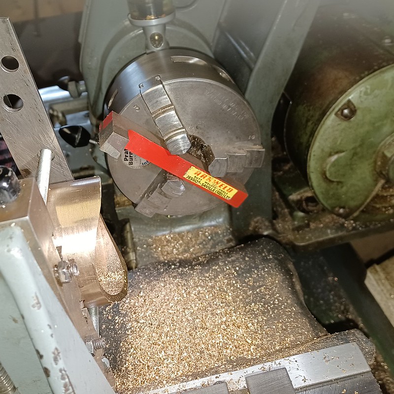 20230624_171447 20230624_171447 by malcolm brown, on Flickr 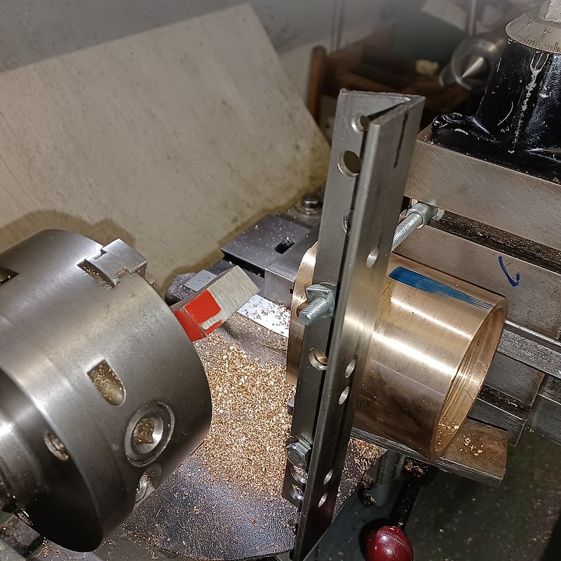 20230624_171459 20230624_171459 by malcolm brown, on Flickr The overhangs were somewhat formidable, but taking very small cuts ( less than 10 thou) and using backgear and a fine auto-feed, it was done. While the set up was in place, I made a start on fly cutting the tube for the sand box too - although as that is a length of 1/16" wall thickness brass tube, it needed a bush inside to stop it deforming from the clamp and even more gently cuts. More progress tomorrow, I hope. Best wishes Malcolm
|
|
mbrown
Elder Statesman
  
Posts: 1,793
|
Post by mbrown on Jun 25, 2023 18:09:46 GMT
Problems, problems...
Carried on with the dome and sandbox today. The sandbox tube was fly-cut in similar manner to the dome but much more slowly as the brass is "sticky" and cuts had to be very small and slow. Even so, the tube moved slightly against the top slide and threw the scallop off centre, so I had to take a good deal more metal off to get it right. As a matter of interest, fly-cutting the base of the sand box took nearly three hours on the lathe.
I made the top for the dome from another piece of bronze from a scrap yard - I had my doubts about it as it machined more like steel, cuts coming of in long coils. But when I tried silver soldering it to the tube, the solder appeared to take OK but did not - my hunch is that it is aluminium bronze. It was too late to try again, using the dodge of salt in the flux.
I tried bending up the plates to make the skirt for both dome and sand box - but the nylon gears on my home-made rollers stripped.... I made the rollers using a set of gears rescued from an old photocopier, so the challenge now is to find a pair of identical gears from somewhere.
I am away now for a few weeks, so the next attempt at all these jobs will have to wait.
Best wishes
Malcolm
|
|
|
|
Post by Roger on Jun 26, 2023 16:01:10 GMT
Problems, problems...Carried on with the dome and sandbox today. The sandbox tube was fly-cut in similar manner to the dome but much more slowly as the brass is "sticky" and cuts had to be very small and slow. Even so, the tube moved slightly against the top slide and threw the scallop off centre, so I had to take a good deal more metal off to get it right. As a matter of interest, fly-cutting the base of the sand box took nearly three hours on the lathe. I made the top for the dome from another piece of bronze from a scrap yard - I had my doubts about it as it machined more like steel, cuts coming of in long coils. But when I tried silver soldering it to the tube, the solder appeared to take OK but did not - my hunch is that it is aluminium bronze. It was too late to try again, using the dodge of salt in the flux. I tried bending up the plates to make the skirt for both dome and sand box - but the nylon gears on my home-made rollers stripped.... I made the rollers using a set of gears rescued from an old photocopier, so the challenge now is to find a pair of identical gears from somewhere. I am away now for a few weeks, so the next attempt at all these jobs will have to wait. Best wishes Malcolm I agree, that sounds like it was Aluminium Bronze. To me, it machines like 316 Stainless. |
|
mbrown
Elder Statesman
  
Posts: 1,793
|
Post by mbrown on Jul 15, 2023 17:11:36 GMT
Dome cont.Back in the workshop after an absence of several weeks, the first job was to replace the broken nylon gears on my bending rolls with new ones of steel, bought cheaply off ebay. That allowed the base of the dome to be rolled to the correct radius. As Roger surmised, the top of the dome was indeed Aluminium Bronze - at any rate, the trick of putting salt in the flux worked fine and I got good penetration of the silver solder (although a slight gap remains, as seen below, on the outside. That will be dealt with using filler at a later stage.) Next up, the base was roughly cut to shape and size and held in place with a long 8 mm bolt while it too was silver soldered to the radius fly-cut on the base of the dome. 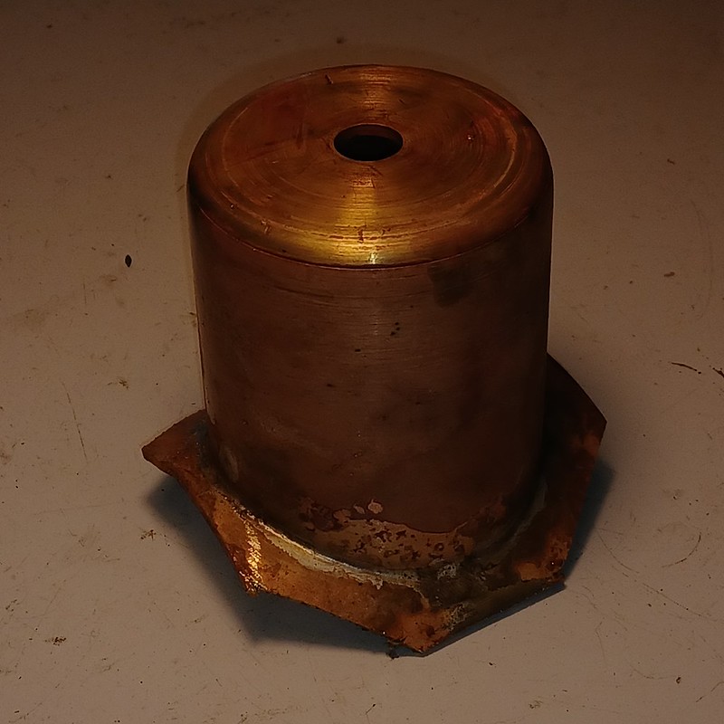 20230715_142651 20230715_142651 by malcolm brown, on Flickr The dome was then chucked in the lathe and the base turned to size around the periphery and the bottom plate bored out to the diameter of the inside of the dome. 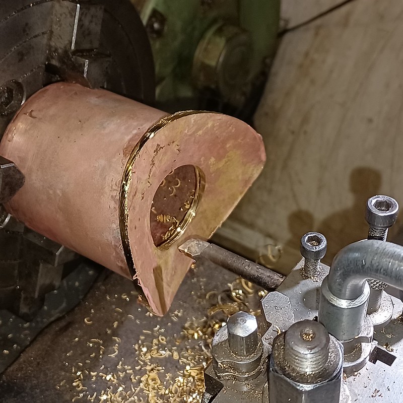 20230715_144657 20230715_144657 by malcolm brown, on Flickr The prototype's dome has a very small radius at the base, not a sharp angle, so I needed to blend in the join between the main tube and the base plate. I bent up a piece of 5/32" half round beading, left over from the tender, with the curved side facing into the join, then soft soldered it with plumbers solder, allowing plenty to build up and then "wiping" the joint. Then it was a matter of blending it all together, using sanding drums in the Dremel, files and emery cloth, to get it smooth. Here is is with the smoothing process just beginning and some of the wiped join still visible.  20230715_153643 20230715_153643 by malcolm brown, on Flickr Some hours later, a reasonable dome is the result. It still has to have the sides cut away at the bottom to clear the steam take-offs on either side of the dome, and the hole in the top will be enlarged into a rectangle to clear the safety valves. Those jobs will be done to place. 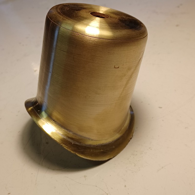 20230715_164902 20230715_164902 by malcolm brown, on Flickr It's good to be back in the workshop! Best wishes Malcolm
|
|
mbrown
Elder Statesman
  
Posts: 1,793
|
Post by mbrown on Jul 22, 2023 19:38:08 GMT
Sand BoxHere is the sandbox, made in exactly the same way as the dome. I don't seem able to get the light right for photos without over emphasising any scratches and blemishes - it's not as bad as it looks! 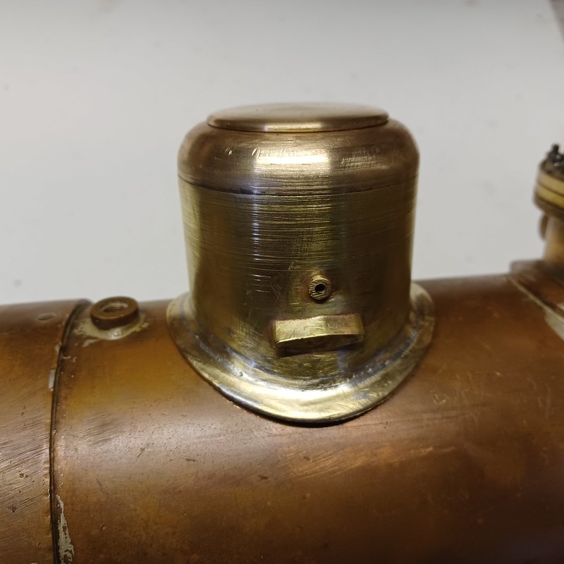 20230722_181205 20230722_181205 by malcolm brown, on Flickr The sand pipe outlets on either side were an interesting exercise. I started with a length of 1" x 1/4" brass and, with the machine vice set at an angle on the mill, machined the elongated diamond section at each end. 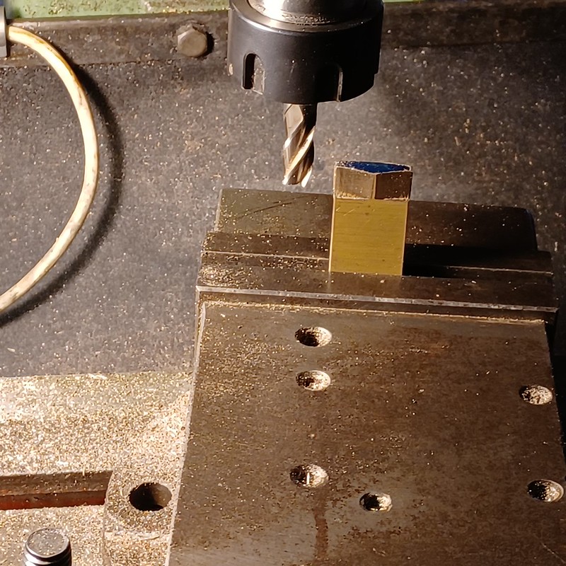 20230716_162544 20230716_162544 by malcolm brown, on Flickr Then, with the vertical slide set at an angle on the cross slide, and a fly cutter set to cut the diameter of the sand box body, I scalloped the ends to suit the radius of the sand box and the roughly 45 degree angle as they slope downwards. 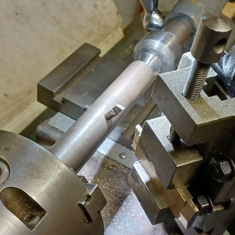 20230716_164831 20230716_164831 by malcolm brown, on Flickr Working on both ends of a longer piece of brass meant that I had something to hold. The milling and fly cutting would have been easier if I had had a swivelling machine vice and a swivelling vertical slide. But I manage by holding them down with one bolt and a clamp on the side that didn't line up with a T slot. Small cuts were the order of the day, but nothing moved. Finally the pieces were parted off... 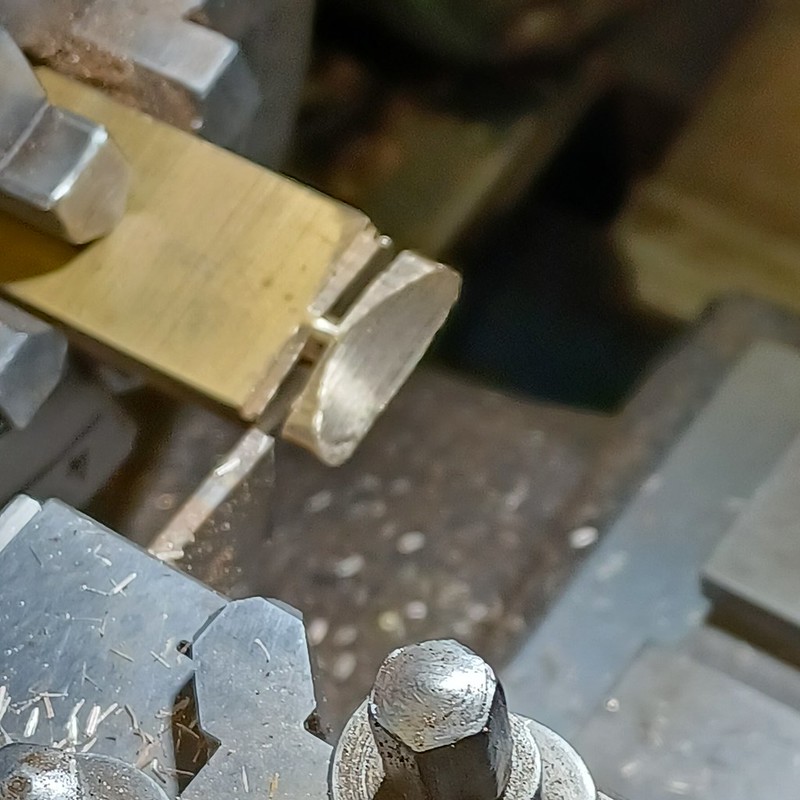 20230716_171210 20230716_171210 by malcolm brown, on Flickr They were screwed to the sand box body (not easy, given all the different angles) along with the bushes for the operating rod, and silver soldered together prior to soft soldering a length of brass wire around the base and blending it in to create a small radius, as with the dome. The lid will be hinged to the body - which is likely to be tomorrow's job. Best wishes Malcolm |
|
mbrown
Elder Statesman
  
Posts: 1,793
|
Post by mbrown on Jul 23, 2023 17:26:42 GMT
Sand Box completedHere is a photo of the lid on the prototype's sand box, taken in the very cramped and ill-lit loco shed at Wiesswasser. The hinge has a little upstand to prevent the lid dropping too far back. 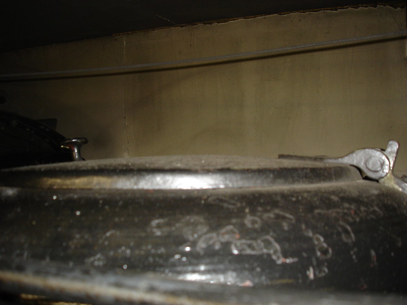 DSC00454 DSC00454 by malcolm brown, on Flickr I started making the hinge by silver soldering together a short length of 1 mm thick brass angle, a length of tube and a small piece of plate to get the level right. 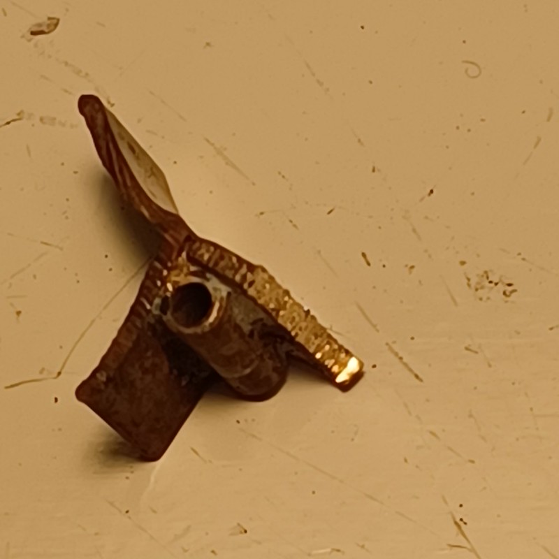 20230723_150958 20230723_150958 by malcolm brown, on Flickr This was trimmed down, fitted to the dome and screwed and sweated in place. The other half of the hinge was straightforward, as was the rather attractive little knob for opening the sand box. The operating rod runs through a bush on one side into a blind bush on the other and is retained by a collar and set screw inside. With its little operating lever, that completed the sand box apart from fitting the sand pipes. 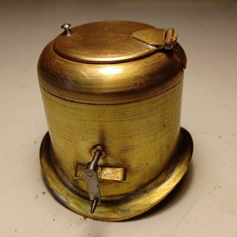 20230723_174315 20230723_174315 by malcolm brown, on Flickr That's it for another weekend. Malcolm
|
|
mbrown
Elder Statesman
  
Posts: 1,793
|
Post by mbrown on Jul 29, 2023 17:40:58 GMT
Steam Bell revisitedSome time ago, I had a bash at making the steam bell which sits behind the chimney on 99 3462. Not having a steam supply, I wasn't able to test it, so I don't know if it works or not - apparently the proportions of the steam and exhaust chambers is fairly critical and I was told at the WEM that some of their steam bells work and some are temperamental. Here is the bell I managed to make.  IMG_20190202_1655498 IMG_20190202_1655498 by malcolm brown, on Flickr And here are the "insides".  IMG_20190202_1651343 IMG_20190202_1651343 by malcolm brown, on Flickr And this is a drawing of the full size bell. 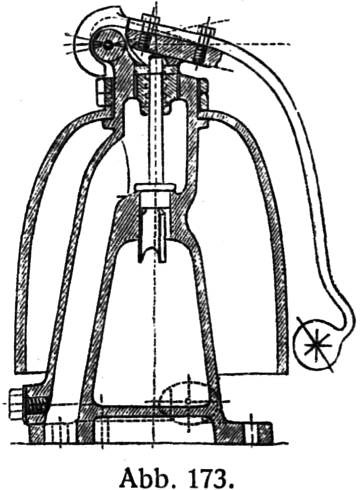 Steam bell Steam bell by malcolm brown, on Flickr The biggest problem I had (apart from finding out if it works) was making the bell itself rather than the mechanism . I tried spinning it, but couldn't get a firm drive with friction alone and a driving pin split the copper. I then tried the "raising" method which took a very long time and gave me a bell with extremely thin metal at the top where the copper had stretched. That's the bell above. I decided to try a third time today, this time pressing a sheet of 20g copper between a turned former and an aluminium tube with a hole of the right diameter (1.5"). I didn't take photos during the operation. It took about 8 annealings and a bit more squeeze each time. I probably made the copper disc a bit over size and this led to a certain amount of puckering at the edge as the pressing proceeded, but the effect was smoothed out to a great extent as the copper was squeezed into the hole. After trimming the edge, here it is, with the former and tube behind. I greased all moving parts to help the copper to flow, but you can see how it scratched the rim of the tube. Nevertheless, a workable bell of the correct size. 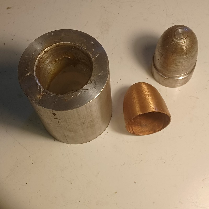 20230729_171327 20230729_171327 by malcolm brown, on Flickr Now to see if I can make the mechanism again and get it to work.... best wishes Malcolm
|
|
mbrown
Elder Statesman
  
Posts: 1,793
|
Post by mbrown on Jul 30, 2023 16:56:44 GMT
Steam Bell MountingNot much workshop time today, but I did complete the mounting for the bell which sits on top of the smokebox. It was made from 1.125" dia BMS, with the bottom flycut to the smokebox radius in exactly the same way as the bases of the dome and sandbox. The triangular flange on which the bell sits was made on the rotary table on the mill - and the whole lot is screwed to the smokebox with a 2 BA socket cap screw. All straightforward but a bit time consuming. 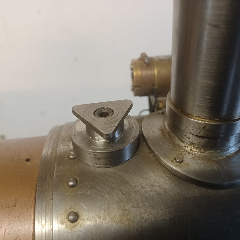 20230730_173500 20230730_173500 by malcolm brown, on Flickr Next weekend is a 2.5" gauge Association rally and after that I am on leave for three weeks including two driving on the TR. So I am not sure whether there will be any further instalments on 99 3462 until September. Best wishes Malcolm
|
|
mbrown
Elder Statesman
  
Posts: 1,793
|
Post by mbrown on Sept 24, 2023 17:56:27 GMT
Picking up where I left off...There has been no work on 99 3462 since my last post at the end of July, but I haven't been totally idle. Two weeks of August were spent very pleasantly driving on the Talyllyn, and I had two excellent outings with the Burma Mines loco at rallies of the National 2.5" Gauge Society. These led, inevitably, to odd bits of maintenance on that loco - at the August rally, the regulator wouldn't close and I ran her for several hours on the reverser - with a two start thread, a half turn of the reverser handle brought speed down to a crawl, but still with four nice beats, and a touch more stopped her, so I obeyed all signals! Easing the spindle for the ball (it's a Gordon Smith valve) meant it worked properly at the second outing. Also, the vacuum ejector wasn't pulling its usual 15" and hunting down the problem took ages - it turned out to be a crack in the swan neck on the driving truck, but by the time I had found it, I had dismantled the ejector for testing - whereupon I found my large vacuum gauge was broken and work stopped until I could get a new one. When I got her on the track at Rugby a couple of weeks ago, I found that I'd lost one of the vacuum pipe couplings and also the cap off an oil cup - both relatively easily made again, but enough to delay work on 99 3462 a bit longer. But today, I managed an hour assembling the connecting rods. I was most puzzled that, without them, the wheels turned very freely with no binding, but with them, and especially after adding the return cranks, the wheels bound up solid at one point of the stroke. Wrongly, I started with the brasses in the connecting rods, thinking they were too wide, but a skim off them made no noticeable difference. Eventually, I noted that, without the connecting rods, the coupling rods on one side tended to flick outwards along the crankpin as the wheels turned. After much messing about, assembling and disassembling, and not a few rude words, I found that the coupling rod was hitting the motion bracket. As the bracket was angled, it just deflected the rod a little - until the connecting rods and return cranks were added which prevented any sideways movement. It was remedied by grinding a little off the motion bracket at the point of interference and slightly thinning the coupling rod as I found I had made one a little thinker than the other. The wheels now rotate nicely. The picture below just shows the point of contact between the motion bracket and the coupling rod. 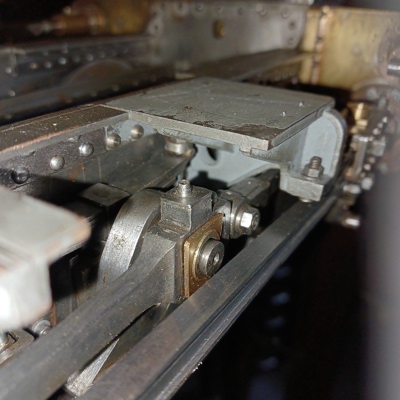 20230924_173847 20230924_173847 by malcolm brown, on Flickr I also trimmed the piston rods to length ready for attachment to the crossheads with a cotter. At the moment, the rods are a very tight fit - almost a drive fit - in the crossheads and will need a little easing to get them in the right position. All being well, the cotter slots and cotters will be next on the agenda. Meanwhile, here is what the chassis is looking like.... 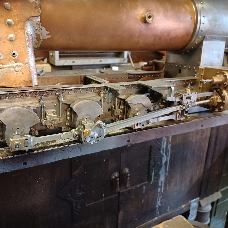 20230924_180516 20230924_180516 by malcolm brown, on Flickr Best wishes. Malcolm
|
|
mbrown
Elder Statesman
  
Posts: 1,793
|
Post by mbrown on Oct 8, 2023 17:30:28 GMT
Crosshead cottersProgress on 99 3462 has been slow and is likely to remain so for a while as "life" and "work" make increasing demands. But I have not been entirely idle and the latest step forward has been to cotter the piston rods to the cross heads. I decided to do a bit better than the usual taper pin and have made proper flat cotters, although the piston rod is a parallel fit in the cross head, not a taper as in full size. Having set the cross heads in the correct position on the piston rods (they are a tight push fit), I set up the cross head and rod in the vertical slide, at the angle of the cotter. I then put two 1/16" holes through the lot as below: 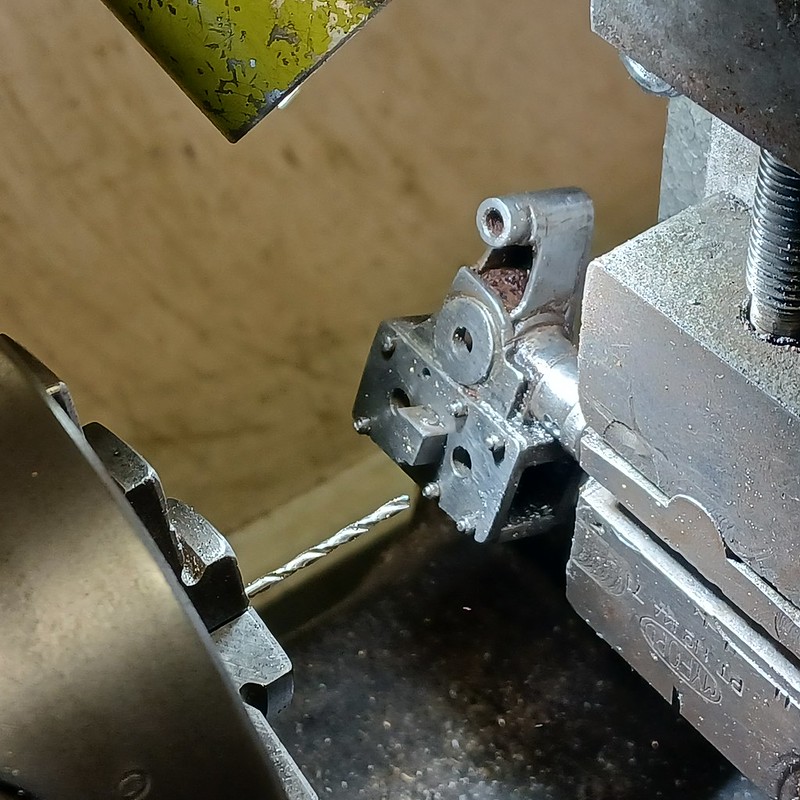 20230930_161101 20230930_161101 by malcolm brown, on Flickr At this point, there was a hiatus as I remembered that, ages ago, I had broken my long 1/16" slot drill and it took a week to replace it. But once it had arrived, I opened out the two holes into a slot. In fact, the new slot drill was a 1.5mm one, so it took a little tweaking to open the slot out to 1/16". The gouges on my machine vice show up very badly here!  20231007_142422 20231007_142422 by malcolm brown, on Flickr To make a tapered slot, I then re-set the vertical slide using a prepared template - a simple piece of 1/8" aluminium with one edge milled at the desired angle. Then used the slot drill to gently open up one side of the slot to a taper. 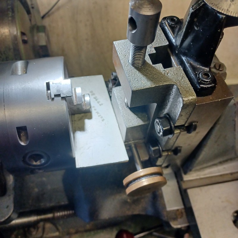 20231007_142636 20231007_142636 by malcolm brown, on Flickr The same template was used in the machine vice to mill down a piece of 1/16" gauge plate to make the cotter. Here is the blank, still on the parent metal, and over-long as the extent to which it protrudes each side of the cross head depends a lot on the fit. The edges were carefully rounded to suit the slot. 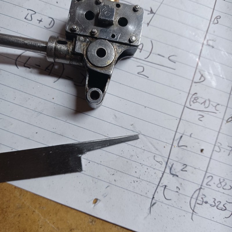 20231007_150053 20231007_150053 by malcolm brown, on Flickr The cotter was then very carefully fitted to the slot so that it dropped into place with no slop - a small tap with a drift then locked it into place. Once the ends had been trimmed, a No.60 hole was put in the tail to take a tiny split pin as a safety cotter. If the main cotter were to work loose, it wouldn't drop out completely and risk the piston rod becoming detached. I don't know if this is general practice everywhere, but all the Talyllyn locos have safety cotters like this. 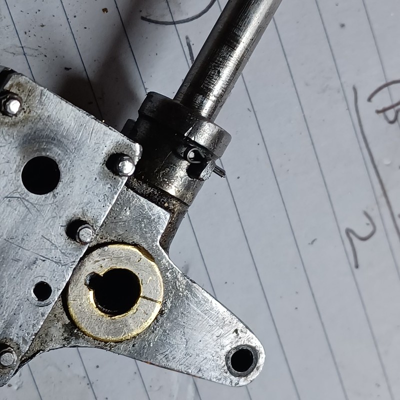 20231007_152143 20231007_152143 by malcolm brown, on Flickr And here it is in situ on the loco. A lot better looking, in my view, than a taper pin - but a lot more work too....  20231007_170815 20231007_170815 by malcolm brown, on Flickr That is it now, for a few weeks. I am hoping to get back to more regular workshop sessions during November. Best wishes Malcolm |
|
mbrown
Elder Statesman
  
Posts: 1,793
|
Post by mbrown on Dec 17, 2023 18:47:10 GMT
Top Plating and Hatch CoversAfter many weeks when circumstances have kept me out of the workshop, this weekend saw a gentle return to tackle further work on the frames. As seen below, the frames on 99 3462 (and most of her sisters) are plated over across the top. This is rivetted on and appears to be structural. I will need the plating to be removable so that I can paint the complex arrangement of stays etc. between the frames, but as my frames are of thicker than scale steel, and as the bracing is quite extensive, I don't anticipate any structural weakness.  lokomotive-1985 lokomotive-1985 by malcolm brown, on Flickr As is also visible in the picture, there are "hatch covers" over each axle centre, made of thin plate held in place with a few set screws. I have reproduced these, but with a different approach for each of the three. The main pieces of the plating was laser cut to my drawings some time ago, as were the hatch covers (from 1 mm steel) and doublers of 3 mm steel which are the same size as the hole the covers fit over. By fixing these together, the hatch cover is located symmetrically over its hole and shouldn't distort. The rear cover may usefully be made removable as it can give me access, in due course, to the whistle. The middle cover doesn't need to come off, and the front cover needs to be easily removable for oiling the pump eccentric. Here are the two parts of the rearmost cover which have to yet been assembled. It will be held in place by the tab which locates under the top plate, and by two out of the eight peripheral set screws (10 BA). Also, here is the finished front cover, upside down, which locates with the tab and a spring clip so that it can be quickly pulled out but won't fall off if the loco is inverted. The middle cover doesn't need to be removable so is held on with all eight set screws. 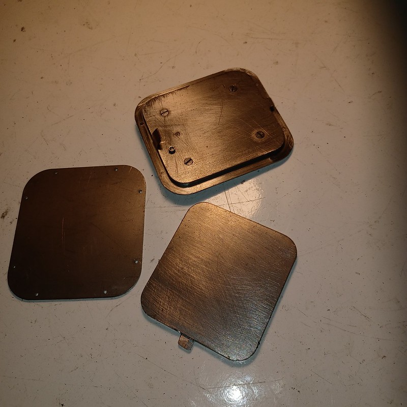 20231217_175552 20231217_175552 by malcolm brown, on Flickr And here are the front two covers in place on the top plates. The latter will be bolted to the frames through the vacant holes using round headed screws to match the dummy rivets. The screw protruding on the front cover is to enable it to be lifted out when necessary. The prototype actually has just such a screw and nut on the top plate - presumably a redundant fixing for some part or other - but not on the hatch cover. I have just used modeller's licence to shift it by about a foot from its place on the big engine! 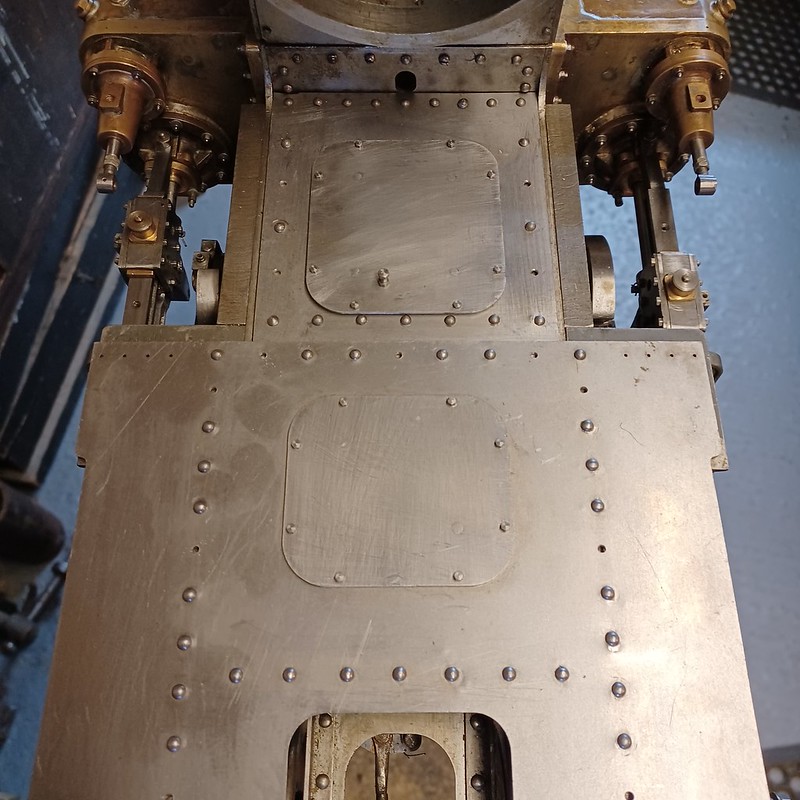 20231217_175707 20231217_175707 by malcolm brown, on Flickr It's good to be back at work on the engine.... Best wishes, Malcolm
|
|
mbrown
Elder Statesman
  
Posts: 1,793
|
Post by mbrown on Dec 21, 2023 17:52:02 GMT
Top Plating CompletedAnother couple of sessions in the workshop and the top plating, complete with its three hatches and angle edging, is finished. The angle at the edge is 3/16" deep. The 3/16" angle one can buy is very thin, hard to bend and vulnerable. On the other hand, cutting it down from 1/4" x 1/4" x 1/16" angle, as I did on the Burma Mines loco, leaves it very heavy and, in the current instance it would have had to be thinned further to get around tight spots. So my compromise was to get a metre of 10 x 10 x 1 mm brass angle from B&Q and trim it down with a slitting saw in the mill to 3/16" high and deep. The countersunk screws holding the front end plates are exactly as on the prototype where large slotted countersunk screws are used in a number of locations. 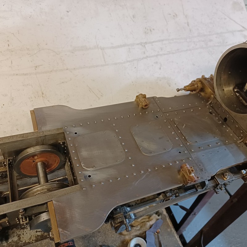 20231221_172122 20231221_172122 by malcolm brown, on Flickr Here it is with the rocker boxes for the expansion links lodged in place. These - and the weigh shaft bearings when I make them - are bolted to the frame brackets through the top plating, so the latter had to be in place before they were fitted. Both the expansion link rockers and the weigh shaft bearings will have to be located accurately at the correct distance from the driving axle - which can't be measured direct. I have a plan for how to do that which I hope to try out tomorrow.  20231221_172216 20231221_172216 by malcolm brown, on Flickr Best wishes Malcolm |
|
mbrown
Elder Statesman
  
Posts: 1,793
|
Post by mbrown on Dec 22, 2023 17:50:04 GMT
Establishing the expansion link pivot positionAfter mulling the problem over for some weeks in odd moments, I arrived at what seems like a satisfactory way to establish, first the position of the driving axle in relation to the top plating and, second, the position of the rocker boxes for the expansion links. First, I prepared a slab of steel which was clamped to the rear buffer beam. Along its centre lines, top and side, I put the loco centre line exactly half the axle length from the outer edge of the plate. So, with the plate clamped to the buffer beam with the centre coinciding with the centre of the buffer beam, the outer edge of the plate was in the same plane as the axle end. I then drilled small centre holes on the top edge to coincide with the centre of the frame plate and on the end, the same height below the frame top as the axle centre. 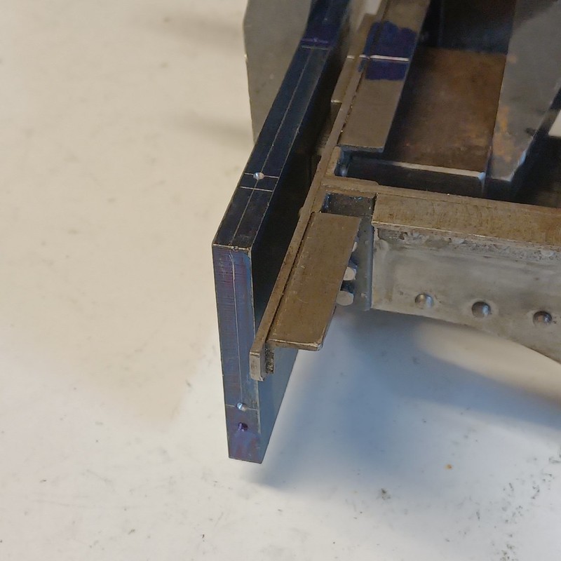 20231222_154236 20231222_154236 by malcolm brown, on Flickr Then, blatantly copying an idea from David in his Sisyphean thread, I made a simple trammel and set it to measure from the centre in the axle end and the centre in the clamped-on plate. 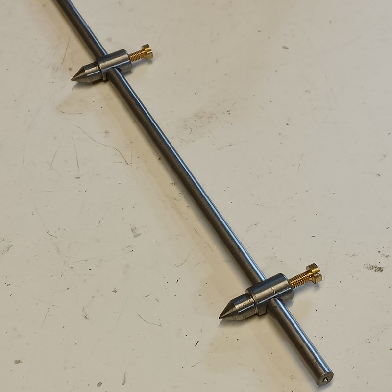 20231222_155225 20231222_155225 by malcolm brown, on Flickr Maintaining the trammel points, it was then easy to transfer one point to the centre which aligned with the frame and scribe a short arc with the other point to cross a scribed line marking the position of the frame edge. This was repeated on the other side and joining the two points gave me the line of the driving axle.  20231222_155320 20231222_155320 by malcolm brown, on Flickr I knew the correct distance of the rocker boxes from the driving axle, and it was straightforward to draw another arc exactly that distance from the axle centre, again coinciding with the frame line. That gave me the centre line for the rockers. The rocker shafts are 1/4" dia, so I drew a parallel line 1/8" each side of the centre, threaded the rocker boxes onto a length of 1/4" silver steel, and could then set them using a small square aligned with the parallel lines. 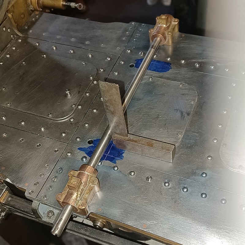 20231222_162252 20231222_162252 by malcolm brown, on Flickr .. at which point family arrived for Christmas which may put a block on progress - although I may negotiate an exeat at some point! Best wishes Malcolm
|
|
 20230603_145327 by malcolm brown, on Flickr
 20230603_150903 by malcolm brown, on Flickr


