timb
Statesman
 
Posts: 515 
|
Post by timb on Aug 3, 2020 15:29:22 GMT
Malcolm, I am even more impressed now, I would have to draw it all up first I think, at least for the part I am making.
I guess some do, some draw, probably explains why my locos are taking so long!!
Fantastic work!!
Tim
|
|
mbrown
Elder Statesman
  
Posts: 1,874
|
Post by mbrown on Aug 3, 2020 19:30:43 GMT
Thanks Tim - I suspect I would have fewer problems to sort out at later stages if I drew everything out first, but I have never been very good with a pencil whereas I can "see" the thing taking shape on the bench. I have had a few more scribbling sessions today, working out the position of some of the hole sin the main frames. The frames were my very first venture into CAD and came back very nicely cut out from MEL - but at that stage I hadn't got the confidence to set out the holes for laser cutting. Some of them are being located from photos, sketched out and then marked on the frame plate, but the holes relating the hornguides and springing are more or less identical for each axle so I have made a simple jig to get them all the same. Here is the frame plates and buffer beams as received from MEL - the horn openings are slanted on one side as the prototype has an adjustable wedge - which I will make as a dummy integral to the horn guide. My one bit of drawing board work, to set out the centres and clearances is underneath.  IMG_20200116_202043 IMG_20200116_202043 by malcolm brown, on Flickr The jig is based on a carefully shaped piece of 4 mm steel which fits the horn opening precisely. It is bolted to another strip of 4 mm plate and the holes for horncheeks and suspension points marked out and drilled. Yes, one hole did go a bit awry - I forgot to put in the offset to accommodate the slope on that side - but I stopped in time and the blemish is only on the surface. The hole actually goes through in the correct location.  IMG_20200803_172935 IMG_20200803_172935 by malcolm brown, on Flickr This then locates firmly on the frame and the holes can be drilled through. If I had been doing a proper job I might have used gauge plate and hardened it, but each hole is only going to have to guide the drill four times so it didn't seem worth it (and I didn't have any gauge plate anyway!)  IMG_20200803_173034 IMG_20200803_173034 by malcolm brown, on Flickr When the other holes have been marked out tomorrow, I can start drilling..... Malcolm |
|
mbrown
Elder Statesman
  
Posts: 1,874
|
Post by mbrown on Aug 4, 2020 20:25:10 GMT
Before I got started on drilling the main frames, a couple of parcels arrived from M-Machine Metals in Darlington and I was able to get back to work on the tender - making a start on the axleboxes. Here's a reminder of what they look like, although it seems clear that the hinge for the front plate has broken at some time and been replaced with a fabricated repair which I don't intend to copy.  DSC00447 DSC00447 by malcolm brown, on Flickr I started with a strip of 5/16" Phos. Bronze 7/8" wide and milled a 3.5 mm slot on each side to fit snugly within the horncheeks ( I find that I am happily, but probably certifiably, mixing imperial and metric units on this model - it seems to work so far). Then I cut them into four pieces and scalloped the top edges with a 1/2" end mill. In my first batch of CNC drawing and laser cutting, I got the axlebox lids made in steel so the next job was to shape the body of the axlebox to match the profile. I did this by putting a length of 5/8" square brass in the V block on the mill and taking off two corners until the land between them was 1/4" wide, and just trimming the bottom two corners.  IMG_20200804_161505 IMG_20200804_161505 by malcolm brown, on Flickr The sharp corners were gently blended with a file and then four pieces parted off in the lathe. Each of these then had the sloping front put on using the "vice held in a vice" method which I picked up off this forum (sorry, I can't remember who I learned it from, but many thanks anyway!).  IMG_20200804_172521 IMG_20200804_172521 by malcolm brown, on Flickr That's as far as I got before having to clean up to then take my better half out for our first meal in a restaurant since lock-down began - I'm writing this up now, slightly under the influence of good food and ale! After a good night's sleep I hope to get the axleboxes finished tomorrow Malcolm |
|
mbrown
Elder Statesman
  
Posts: 1,874
|
Post by mbrown on Aug 5, 2020 18:12:31 GMT
Almost finished the axleboxes today. Picking up from where I left off yesterday, the next job was to cut two slots in the inner face of the brass section into which small strips of brass (1/16" x 5/32") go in order to form the little gussets.  IMG_20200805_140436 IMG_20200805_140436 by malcolm brown, on Flickr I didn't photograph the next stage, but the bronze sections were then drilled to accept the little boss I left on the brass part and the two were pressed together with the brass strips captive between them. A small piece of 1/4" x 1/8" brass was screwed to the top with a 10 BA sacrificial screw, and the lot silver soldered together. The ends of the brass trips were easily shaped off with a file to form the gussets. Then each was mounted in the 4 jaw chuck and set to runt rue to the hole drilled earlier. They were then drilled through at 1/4" and opened out for 5/8" depth to 7/16", with a 5/16" ID Oilite bush pressed in. Although nominally 7/16" OD, Oilite bushes are a couple of thou oversize and press into a drilled 7/16" hole just nicely. I believe the pressing then brings the ID to precise size, but I haven't measured it yet. Here are the four boxes - one with the bush fitted, one ready to be bushed and the others showing the through-hole. As the bore was opened out to a slightly greater depth than the length of the bush, there is a small well at the end of the axle which should hold oil and keep the bush lubricated.  IMG_20200805_174935 IMG_20200805_174935 by malcolm brown, on Flickr Then the lids came next - so far, I have finished oen to rpove the concept and the other three can be finished tomorrow. The small lid which I had laser cut, has a piece of 3 mm BMS, drilled through at 1/16", silver soldered to the top edge. The bit of 1/4" x 1/8" brass which sticks out ahead of the front face of the box, was then drilled through to take the hinge pin (a 1/16" rivet with the head turned to a cheesehead). The little spring of phos. bronze strip was rivetted on and the top part of the hinge filed so that it locates firmly in the open and shut positions. Here it is in both positions. My wife says it looks like a miniature toilet …  IMG_20200805_184512 IMG_20200805_184512 by malcolm brown, on Flickr  IMG_20200805_184534 IMG_20200805_184534 by malcolm brown, on Flickr That's it for today. Malcolm |
|
mbrown
Elder Statesman
  
Posts: 1,874
|
Post by mbrown on Aug 6, 2020 18:47:02 GMT
A long session in the workshop today saw all four axleboxes finished, complete with lids etc. Each one needed a fair bit of work to make it a smooth sliding fit in its slot - not least because I had left some rivet heads a bit too close to the inside flanges and they needed trimming back. Then the axles were turned up in the usual way - straightforward but time consuming - and the wheels pressed on, and then it was time to see if it all fitted.....  IMG_20200806_182001 IMG_20200806_182001 by malcolm brown, on Flickr It all slid together as expected and a check with a Vernier showed the axles to be parallel within a couple of thou which I was pleased with.  IMG_20200806_182241 IMG_20200806_182241 by malcolm brown, on Flickr I think it looks the part! By the way, having lightly pressed in the oilite bushes, I found there was no way the journals, which I had turned to precisely 5/16", would go in. I took off another 3 thou and they entered the bearing but were more of a hand push fit than a running fit. Now the wheels are in the frames, they go round when I lean on the frame and push, but it's like having a dragging brake. I was under the impression that it was a mistake to ream out an oilite bearing as it damaged the texture of the surface which retains the oil. But equally, I don't want to take any more off the journal as I haven't got a "putting on tool" ... Any suggestions? Maybe they'll bed in... Hornstays and a few other odd jobs tomorrow. Now that the wheels are in place I realise that, when I set out the holes in the frame, I completely forgot about the brake hangers. There are a couple of hex head bolts on the frame of the prototype which look as if they are for the hangers, so I must try and work something out which looks right. Best wishes Malcolm |
|
stevep
Elder Statesman
  
Posts: 1,078
|
Post by stevep on Aug 6, 2020 19:00:42 GMT
I believe there are quite detailed specifications about how big a hole should be for an oilite bush to be pressed in so it gives the right ID afterwards.
Searching the web gives lots of sites with guidance on that.
P.S. The tender chassis looks great.
|
|
mbrown
Elder Statesman
  
Posts: 1,874
|
Post by mbrown on Aug 6, 2020 19:25:46 GMT
Thanks Steve - I should have done my research... I just had it in my head that the bearing was a light press fit in a drilled hole of nominal size. It certainly went in quite easily. Anyway, it's too late to do it again so I may have to adjust the diameter of the journal by another thou or two.. We live and learn.
Best wishes
Malcolm
|
|
|
|
Post by ettingtonliam on Aug 6, 2020 20:52:37 GMT
I know the accepted intelligence is that you shouldn't ream an oilite bush or fix it in with Loctite, but I did both on a bush in a gear hub running on a lathe spindle, and it ran fine in 20 years of my ownership, and was still running when I sold it.
|
|
mbrown
Elder Statesman
  
Posts: 1,874
|
Post by mbrown on Aug 7, 2020 20:05:18 GMT
The "problem" with the oilite bushes is solved. The fit on the journal was fine - the difficulty was that, stupidly, I had forgotten that the axleboxes were made "handed" and just fitted them as they came to hand. There can't have been more than a thou or two in it, as the axles still revolved fairly well and were parallel to each other - but they weren't precisely at right angles to the frame, hence the slight binding. After a bit of thought, and some trial and error, the axleboxes are now in their correct locations and the wheels turn freely at last. I must be getting to the stage where "senior moments" become increasingly frequent….. I have now numbered them so it doesn't happen again. The hornstays are probably the simplest ever - 2" strips of 1/4" x 1/16" steel. The reason for the countersunk screws on the frame angles now becomes apparent - they give clearance for the hex head screws.  IMG_20200807_201830 IMG_20200807_201830 by malcolm brown, on Flickr Today's other job was to modify the coupler socket to give some clearance for the brake shaft. By skimming 1/16" off its depth and reducing the diameter of the boss, everything now clears - just. The brakeshaft has its arms fitted, although at present only with low strength Loctite while I decide how to secure them. The prototype has them located with gib cotters, but that would be fiddly in this scale. I might give it a try though. (I am amazed at the roughness appearing on the top surface of the angles - it's all in the photographic conditions and not really visible to the eye - but I guess a rub over with emery will sort it out). 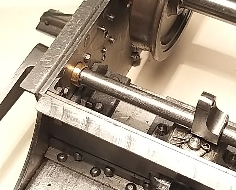 IMG_20200807_195250 IMG_20200807_195250 by malcolm brown, on Flickr 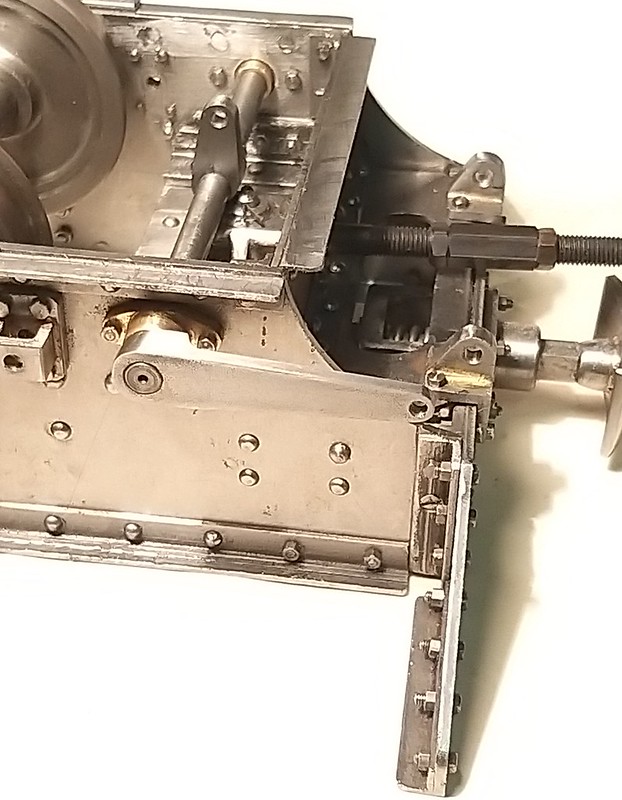 IMG_20200807_195223 IMG_20200807_195223 by malcolm brown, on Flickr One consequence of raising the coupler pocket to clear the brakeshaft is that I had to file out the opening in the front diaphragm stay to clear the drawbar, eating into the top angle a bit. I left it a wee bit ragged as, lo and behold, exactly the same cut away has been done on the real thing (the shot at the bottom is looking back from under the firebox to where the drawbar enters the tender). I am not sure why - presumably O&K knew how to line up a drawbar without fouling the brake gear when it was built - but now we have a case of the model following the prototype even in the way it has been hacked about!  IMG_20200807_202926 IMG_20200807_202926 by malcolm brown, on Flickr  DSC00508 DSC00508 by malcolm brown, on Flickr That brings me to the end of a week's leave spent mainly in the workshop (when not catching up on sleep). More in a few weeks' time I hope. Malcolm |
|
mbrown
Elder Statesman
  
Posts: 1,874
|
Post by mbrown on Aug 25, 2020 18:47:21 GMT
Back home after a fortnight on the Talyllyn - very good to have had some time on the footplate again and to see some full trains (albeit with every other compartment locked out of use..... First act on return was to order a casting for the brake blocks on the tender. The wheels being just over 2" diameter, the casting for the 3.5"g Tich looked just right. Ordered on line from GLR Kennions at 0900 Monday - on my desk at 1000 Tuesday, which is pretty impressive service (usual disclaimer). The casting is good - but it illustrates a problem that seems to be perpetuated quite often in models - the ends of the brake blocks are shown here as radii to the wheel centre. But really they should be parallel to one another so that the area of the brake shoe presented to the wheel is constant as the brake block wears down.  IMG_20200825_172706 IMG_20200825_172706 by malcolm brown, on Flickr This is not Kennions' fault as this was how LBSC drew them, as I recall - although he should have known better from his full-size experience. Fortunately there is plenty of metal in the casting so I should be able to get around this. I also ordered a brake block ring for the 5"g Tich which is just right for the driving wheels - and that is a much better shaped casting. Next weekend should give me a chance to get started on the tender brake gear. Best wishes Malcolm |
|
mbrown
Elder Statesman
  
Posts: 1,874
|
Post by mbrown on Aug 29, 2020 18:40:41 GMT
So today's job was to turn the rather lumpy brake block casting into a finished job. My tender wheels a wee bit bigger than Tich driving wheels, and it seems the casting was pretty near the limit for Tich, so the brake blocks will have to represent a worn set (actually, the blocks on the tender when I visited WEM last year were definitely near the end of their life, so they will be "prototypical"!) I bored them out in the lathe in the usual way, having faced both sides to get the thickness right. Because there was not much spare material in the blocks, my first plan of slotting the back with a parting tool in the lathe was out as the curved slot would have eaten into the ends of the block. So, having marked out and drilled the holes for the hanger pins, I mounted them in the chuck on the rotary table and used a slitting saw in the mill.  IMG_20200829_160731 IMG_20200829_160731 by malcolm brown, on Flickr After that, I needed to part each block off from the ring, making sure the ends were parallel. Knowing the holes were at 90 degrees to each other, I set the ring up in the milling vice with two pegs (No,42 drills, in fact) to set it level and then cut almost through with a slitting saw at the same height each time. I didn't cut all the way through as I wanted to have enough material to hold. 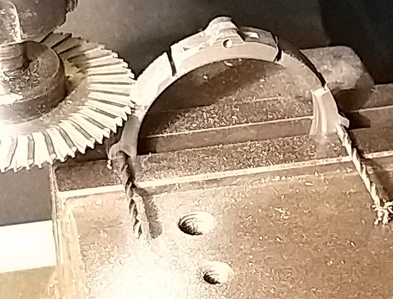 IMG_20200829_161908 IMG_20200829_161908 by malcolm brown, on Flickr Here is the ring after all the machining. I had shaped around the pin holes with a 1/4" endmill - I probably should have used something larger to get a bigger radius. I was going to use a hacksaw to separate the individual blocks, but in fact the little material I had left between them allowed them to be snapped off neatly by hand.  IMG_20200829_162324 IMG_20200829_162324 by malcolm brown, on Flickr The shape of the blocks is not quite right but it does capture the rather long blocks of the prototype, I think. This shot of Sven Schlenkrich (who was my very genial host last year) changing the blocks on the loco shows the general shape - the tender blocks are similar - and shows that I needed a bigger radius between the pins and the back of the block. But as they are completely invisible once fitted to the tender, I am content with them as they are.  galerie_2013_04_26_br galerie_2013_04_26_br by malcolm brown, on Flickr So here are the four tender blocks. While the lathe etc. was covered with cast iron turnings, I made a start on the loco brake blocks, made from a casting intended for the 5"G Tich. This is a much beefier casting with enough material for eight blocks - though, despite 99 3462 being an eight-coupled loco, only two of the axles are braked. By close of play this evening I had machined the ring and the next step will be getting the profile right.  IMG_20200829_163413 IMG_20200829_163413 by malcolm brown, on Flickr Best wishes Malcolm |
|
mbrown
Elder Statesman
  
Posts: 1,874
|
Post by mbrown on Aug 30, 2020 16:33:05 GMT
Brake blocks for the loco now finished, although it will be many months (years?) before I need them... Exactly the same method as for the tender brake blocks, just different sizes. I think I have got the profile of the back of the block about right this time, using a 3/4" endmill rather than a 1/4" one. The ring had enough material for eight blocks so I made eight, even though the loco only needs four. No harm in having some spares, and machining teh spares would be tricky once four had been cut out of the ring, so best to do them all at one go.  IMG_20200830_164845 IMG_20200830_164845 by malcolm brown, on Flickr Malcolm |
|
mbrown
Elder Statesman
  
Posts: 1,874
|
Post by mbrown on Aug 31, 2020 17:32:47 GMT
On we go with the tender brake gear. As I said somewhere earlier, I forgot to mark out any holes for the brake hangers when I did the frames. There are two hex head bolt heads visible on the prototype behind each wheel, which almost certainly are for the hanger brackets. In order to get them in the right place, I made a simple jig to fit closely around the spring hangers. The end two holes are for the holes through the frame - the centre one is to allow me to set up the hanger bracket so that the pin is in the right place. I am guessing at the shape of the hanger brackets as I didn't make any notes of the arrangement when I was underneath it, and my photo collection doesn't show what I need. Here's the jig in place - it was clamped to enable me to drill the frames.  IMG_20200831_151213 IMG_20200831_151213 by malcolm brown, on Flickr The brake hanger bracket was turned out of 3/4" BMS with a cut away to clear other bits and pieces between the frames. I figured that, if it is only fixed to the frame with two bolts, the added surface against the frame should prevent any distortion if ever the brakes are put on hard!  IMG_20200831_164015 IMG_20200831_164015 by malcolm brown, on Flickr While it was in the lathe, I put a 6 BA tapped hole in the back. This allows it to be screwed to the jig by the middle of the three holes and the fixing holes to be spotted through the jig to match the frame holes. 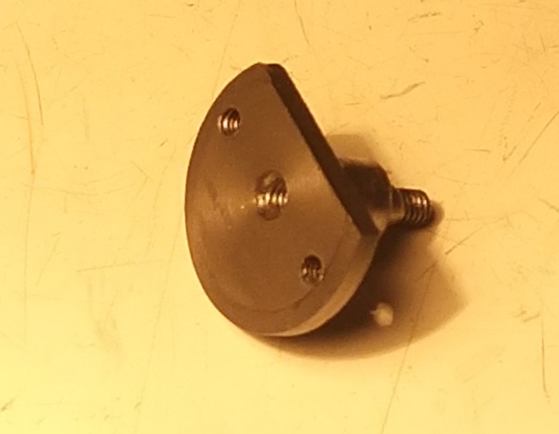 IMG_20200831_164026 IMG_20200831_164026 by malcolm brown, on Flickr Here is a brake block on its embryonic hanger - once in place, it was clear that they needed some adjustment of the hanger profile and the slot in the block, to allow for the right tilt on the block when the brakes are on.  IMG_20200831_163914 IMG_20200831_163914 by malcolm brown, on Flickr Here is the hanger bracket on the frame.  IMG_20200831_174203 IMG_20200831_174203 by malcolm brown, on Flickr - and here it is with the brake block in place. The block is fitted to its hanger by my usual method - in this case, a 3/32" iron rivet with the head turned to a cheesehead, lightly squeezed in the vice so that the pivot is movable but stiff. That way, the brake block can move to fit against the wheel, but doesn't flop about. The pin can be knocked out with a punch if necessary (taking care to support the block so that the cast iron doesn't crack... 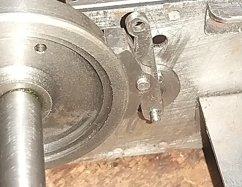 IMG_20200831_174457 IMG_20200831_174457 by malcolm brown, on Flickr By close of play today, I had made all the hanger brackets and hangers, but not had time to assemble it all. Next time, there will be the cross beams and pull rods to complete. Malcolm |
|
dscott
Elder Statesman
  
Posts: 2,440
|
Post by dscott on Sept 4, 2020 0:14:58 GMT
Just having a catch up on your lovely project.
"Not a lot of people know that" if you get a miss drilled hole in the first few seconds.
YOUR JIG.
Do the others and go back and mark off on the other side. Go again. If that fails MIG weld and attempt again!
My favorite is to go along and lightly start all the holes with a smaller drill.
Stub drills or a center drill is good.
Check all the holes... you can tease holes over by tilting the piece. Bashing the side with a centerpunch
and have another go.
Cordless drills are great at moving holes over.
Remembering the importance of doing the last hole first!
David and Lily.
Edit bit.
On my Fowler Complex (Simplex rebuild) I built up my brake blocks out of 3 pieces of plate giving the chunky appearance of the narrow gauge and getting the slot nicely as well. Great tip using 3 mm for the hangers and 1/8" for the middle packing pieces. (CHEATING)
For the first time in History a Simplex has 6 brake blocks!!!!!!
|
|
mbrown
Elder Statesman
  
Posts: 1,874
|
Post by mbrown on Sept 4, 2020 12:17:06 GMT
Many thanks David.
Indeed.... believe me, I have used all those dodges (and sometimes got away with them....)
Best wishes
Malcolm
|
|
mbrown
Elder Statesman
  
Posts: 1,874
|
Post by mbrown on Sept 6, 2020 18:35:33 GMT
This weekend has seen the tender brake gear finished, at least as far as the chassis is concerned. The operating handle is a throw-over affair, rather like a point lever, mounted on the front tender bulkhead, so it will be a while before I attempt that. First, I finished off the brake shaft and levers. On the prototype, both are fitted with longitudinal keys - the one on the long operating lever outside the frame is rather obvious, so I followed the real thing here.  IMG_20200906_140452 IMG_20200906_140452 by malcolm brown, on Flickr The eagle-eyed who compare this picture with an earlier one will see that I originally fitted the lever the wrong way around... in fact, the boss faces outside, not inwards. I made the keyway by drilling a No.53 hole half in the arm and half in the shaft. The half-round slot in the shaft was then squared off with a 1/16" end mill in the milling machine. Once upon a time, I had a nice little Adept hand shaper which would have been just the job for the slot inside the boss. Sadly, it went years ago to make room for the mill. So I squared the inside slot with a needle file. The key is from 1/16" gauge plate. The arm between the frames is fixed with a 3/32" taper pin as it needs to be disassembled from time to time to remove the shaft itself. The taper pin is fitted so that it goes half through the arm and half through the shaft. I like taper pins because a small tap with a hammer at the small end and they are free - no need for drifts or thin punches.  IMG_20200906_143541 IMG_20200906_143541 by malcolm brown, on Flickr Here is a shot underneath the full size tender showing how the brake pull rods are arranged. Incidentally, the small pipe running to the left is a rail-watering device - the loco has a similar arrangement - to spray water onto the flanges to help when rounding sharp curves. Apparently, it has almost completely eliminated flange-wear despite some quite sharp curve son the WEM.  DSC00501 DSC00501 by malcolm brown, on Flickr I made the beams between the brake hangers as fabrications. The end pieces are turned from 1/4" BMS and slotted - the centre part is from 5/16" BMS, also slotted but with plenty left to act as a chucking piece. After they were silver soldered together and cleaned up, the extra material was chucked and the central boss faced off and drilled. After the excess was sawn off, the beam was held in the 4-jaw for the other side to be faced off.  IMG_20200906_160046 IMG_20200906_160046 by malcolm brown, on Flickr The front pull rod is threaded 5/32" x 40, held by 5 BA nuts tapped out to size. The rear pull rod is 1/8" dia silver soldered to the front part and threaded 5 BA. The pin in the fork at the front still needs shortening and drilling for a washer and split pin. The collar with the small grub screw just ensures that there is no side play. In theory, the rodding should keep everything lined up, but the collar makes it certain. 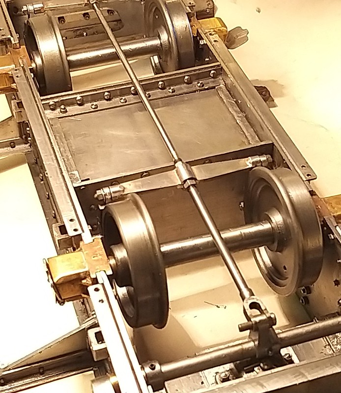 IMG_20200906_180842 IMG_20200906_180842 by malcolm brown, on Flickr Underneath, you can see here how the brake rodding runs through the brake beams and is adjusted by nuts. The front pull rod is a greater diameter than the rear section, so the nuts for the front beam can be run over the rear section.  IMG_20200906_180833 IMG_20200906_180833 by malcolm brown, on Flickr Next job will be springs and spring hangers... I am hoping to have the spring buckles water-jet cut - I have done the CAD drawings but not sent them off yet, so it may be a while before I make much more progress. Never mind - plenty else to get on with! Best wishes Malcolm |
|
mbrown
Elder Statesman
  
Posts: 1,874
|
Post by mbrown on Sept 12, 2020 20:32:43 GMT
As members on this forum remind us from time to time, this is a hobby and we don't have to please anyone except ourselves. So, despite planning to get on with the tender springing today, I found my enthusiasm for that job was lacking and decided to have a bash at the handbrake on the tender, even though I will have nothing to attach it to until the tender body is finished. Here's the prototype's handbrake - I suspect it was a standard O&K fitting. This is looking from the cab back at the tender front.  DSC00443 DSC00443 by malcolm brown, on Flickr And this close up view shows some of the detail of the ratchet mechanism and the ratio of the levers which convert sideways motion to vertical motion.  DSC00451 DSC00451 by malcolm brown, on Flickr You can see how the ratchet teeth only go about 2/3 the way across the width of the quadrant, the pawl being lifted, to release the brake, by the little thumb lever. You can also see that the ratchet quadrant is quite an odd shape, the left hand stop being deeper than the left hand one. The assembly is bolted onto the stand by a bolt through the pivot and a countersunk bolt, just visible behind the thumb lever. I decided to start with the ratchet as the shape was quite challenging to make. I didn't have any round stock the right size so I started with a square of 1/4" BMS, drilled it through and mounted it on a bolt to machine it circular. Then it was held in the outside jaws for the middle to be bored out and recessed - the recess leaves an outer rim from which the stops will appear in due course. Then a bit of careful work in the rotary table on the mill gave me this rather strange shape. But I think you can see the ratchet plate emerging....  IMG_20200912_153301 IMG_20200912_153301 by malcolm brown, on Flickr Back onto the mill, this time with a small rotary table fitted vertically, to put in the ratchet teeth - the cutter came a bit close to the chuck, but there was just room.  IMG_20200912_155836 IMG_20200912_155836 by malcolm brown, on Flickr And here is the (almost) finished part - the stops are over size so that they can be filed to shape once the sweep of the lever is known.  IMG_20200912_161339 IMG_20200912_161339 by malcolm brown, on Flickr The ratchet was then mounted on a piece of 1/6" steel which started as a circle with the circumference the right diameter from the pivot hole. The ratchet was carefully lined up with the edge and silver soldered in place - then a 6 BA CSK Allen screw and nut used to fix it in place on the bracket. The mounting bracket is made from 3/4" steel angle, faced down in the lathe to 2 mm thickness and cut back to measure 5/8" x 3/8". Here is the ratchet plate mounted on the stand, along with the bob weight ready for the lever. The lighting makes the finish look pretty rough, but it is quite smooth in reality. I wish I could find a way to get the light good enough to pick up detail but without exaggerating the surface flaws.... the parts are actually about half the size they appear in the photo. 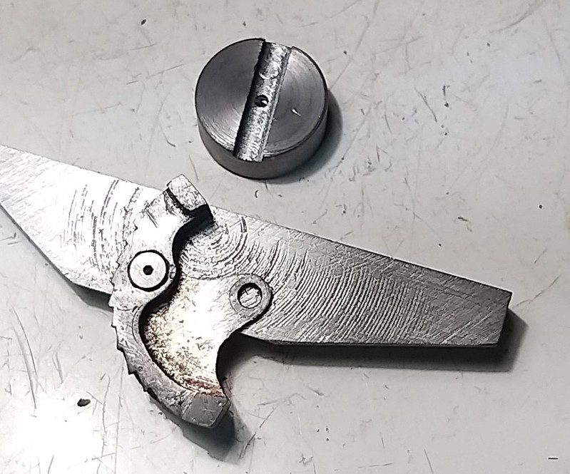 IMG_20200912_180950 IMG_20200912_180950 by malcolm brown, on Flickr The lever was filed to shape and the small lever at the end mounted on a bush to give the right effect of different thicknesses. The bits at the base of the lever will be silver soldered - tomorrow I hope - and then the bore drilled through for the mounting pin.  IMG_20200912_204440 IMG_20200912_204440 by malcolm brown, on Flickr Then there will be the pawl and its thumb lever to make, and the lifting arm which looks like a question mark. I can't do the turnbuckle yet as I don't have a suitable tap and die for a left hand, as well as a right hand, thread. I must contact Tracy Tools next week.... Then I shall have to put it somewhere safe but easy to remember until I have a tender body to bolt it to.... Malcolm |
|
|
|
Post by ettingtonliam on Sept 12, 2020 21:34:13 GMT
That ratchet is a nice piece of work, but is that the mill table I sold you in the photo? It looks even worse than I remember!
|
|
mbrown
Elder Statesman
  
Posts: 1,874
|
Post by mbrown on Sept 13, 2020 8:33:29 GMT
Yes it is! Fortunately (as you will remember) the damage is confined to a fairly small area in the middle and I usually keep the machine vice over it! The table itself is flat and true after you had it reground.
It does the job and got me a decent sized mill at a price I could afford - so no complaints!
Malcolm
|
|
mbrown
Elder Statesman
  
Posts: 1,874
|
Post by mbrown on Sept 13, 2020 9:55:12 GMT
Picking up a point made in the recent thread that has now been closed down - I don't regard the "Build Diary" heading to this thread to imply that it is just for me to post my updates. All comments, criticisms, interventions (even if only marginally relevant) etc. are welcome!
Malcolm
|
|