mbrown
Elder Statesman

Posts: 1,719
|
Post by mbrown on Sept 13, 2020 20:13:48 GMT
Back to work on the handbrake this evening.... The first thing was realizing, after careful scrutiny of my photos, that I had mounted the ratchet too far the left. I had wondered why, having made the parts to the measurements taken from the prototype, why the centre of the ratchet didn't coincide with the centre of the support angle as it appeared to do in "real life". Looking again at the pictures, I saw that I had interpreted the perspective wrong and that in fact, the right hand edge of the ratchet overlapped the tool box on that side instead of coinciding with the edge of the angle. So I filled the rogue hole by tapping it 5 BA and screwing in a stub of steel with some high strength Loctite, then gently peening the ends over into small countersinks. When it was filed flush it was invisible on one side and only slightly noticeable on the other.  IMG_20200913_174931 IMG_20200913_174931 by malcolm brown, on Flickr The pawl was filed up from a tiny piece of 1/8" gauge plate and pressed onto a 3/32" pin.  IMG_20200913_195640 IMG_20200913_195640 by malcolm brown, on Flickr ... and the thumb lever for releasing the pawl is a piece of 3/16" rod with a tab silver soldered onto it and filed to shape. It was then pressed onto the other end of the spindle. I don't think anything more permanent is needed, given the small forces involved. 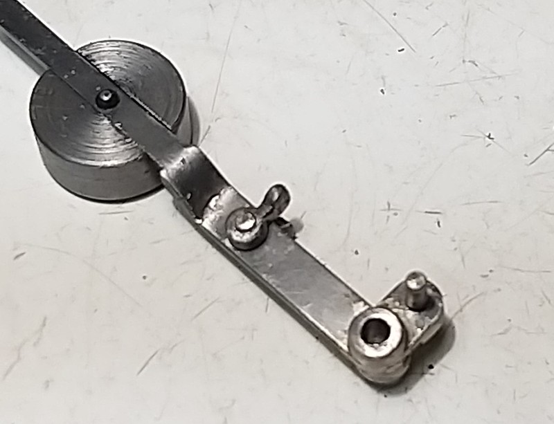 IMG_20200913_195731 IMG_20200913_195731 by malcolm brown, on Flickr Finally, the "?" shaped pull lever was made from 1/8" plate. I have left this over length and it will, in due course, be silver soldered to a length of LH 3 BA threaded rod to go into the turnbuckle.  IMG_20200913_204645 IMG_20200913_204645 by malcolm brown, on Flickr And finally, a shot intended to be as close to the close up picture of the full size handbrake as possible. It shows that I haven't got it perfect, but I think it is a decent representation of a classic Orenstein and Koppell brake lever.  IMG_20200913_204540 IMG_20200913_204540 by malcolm brown, on Flickr More next week, I hope. Cheers Malcolm |
|
|
|
Post by Deleted on Sept 13, 2020 20:28:51 GMT
First rate attention to detail Malcolm.. she's going to be a very special model...
Pete
|
|
mbrown
Elder Statesman
Posts: 1,719
|
Post by mbrown on Sept 13, 2020 20:44:38 GMT
Many thanks Pete.
Attention to detail is all very well, but that ratchet and pawl are a faff to operate in full size and will be very fiddly, reaching between the loco and tender to release the brake, in model size. I may end up not bothering to use the hand brake and then watching it roll off down some gradient!!
Malcolm
|
|
|
|
Post by Deleted on Sept 13, 2020 21:00:51 GMT
You don't want that...there was a close call at my club a few weeks ago...loco in the steaming bay had it's regulator open a little...the owner just managed to grab it as it started to steam off the bay....think it was a B1...that would have hurt falling onto the steaming bay concrete floor.
|
|
|
|
Post by Roger on Sept 13, 2020 21:31:37 GMT
You don't want that...there was a close call at my club a few weeks ago...loco in the steaming bay had it's regulator open a little...the owner just managed to grab it as it started to steam off the bay....think it was a B1...that would have hurt falling onto the steaming bay concrete floor. I'm amazed that steaming bays don't have chocs or owners don't provide their own. People seem to be perfectly happy just firing up with nothing to stop the locomotive rolling off the end for any reason. |
|
|
|
Post by Deleted on Sept 13, 2020 21:45:52 GMT
You don't want that...there was a close call at my club a few weeks ago...loco in the steaming bay had it's regulator open a little...the owner just managed to grab it as it started to steam off the bay....think it was a B1...that would have hurt falling onto the steaming bay concrete floor. I'm amazed that steaming bays don't have chocs or owners don't provide their own. People seem to be perfectly happy just firing up with nothing to stop the locomotive rolling off the end for any reason. When I put 4472 on the steaming bay I tend to use a G clamp and block of wood. In this case though the model was ready to go on the transverser, there are no stops there for obvious reasons. The other end does have steel bars to stop anything rolling off. Pete |
|
mbrown
Elder Statesman
Posts: 1,719
|
Post by mbrown on Sept 13, 2020 21:58:26 GMT
Many German "throw over" handbrake don't have a pawl and ratchet but rely on the weight to keep the brakes on - but on a small model, that isn't nearly enough.
My solution on a steaming bay is to put my toolbox between the loco and the end of the track, only removing it at the last minute. But mine are small locos compared to a 5"g B1....
Malcolm
|
|
timb
Statesman

Posts: 512 
|
Post by timb on Sept 14, 2020 7:15:10 GMT
A lot of work there Malcolm and a worthy result, well done Sir!
Tim
|
|
|
|
Post by runner42 on Sept 14, 2020 7:38:17 GMT
Mechanical tender brakes engaged and the locomotive in mid gear should solve most problems.
Brian
|
|
mbrown
Elder Statesman
Posts: 1,719
|
Post by mbrown on Sept 15, 2020 13:15:46 GMT
I have been rather embarrassed by the way my photos seem to exaggerate all the surface imperfections on my work. OK, I guess I can always do better at getting the filing and machining marks out, but the finished pieces usually look nowhere near as bad n reality as they appear in the pictures. The solution may be to take pictures in natural light, as below. My workshop relies on artificial light (the one small window opens onto a blank fence...) so I may try taking pictures on the study desk instead....  IMG_20200915_140409 IMG_20200915_140409 by malcolm brown, on Flickr Malcolm |
|
|
|
Post by Deleted on Sept 15, 2020 13:20:00 GMT
Looks great Malcolm... I know what you mean by imperfections which the camera loves to pick up, especially if taking a close up. I try to ignore them now as the human eye can't see these small blemishes, more importantly, when the model is completed most small imperfections will disappear to the eye as it tries to take in the whole model...  Pete |
|
mbrown
Elder Statesman
Posts: 1,719
|
Post by mbrown on Sept 20, 2020 16:33:46 GMT
Only a couple of hours for workshop time today, but the handbrake now has its adjusting turnbuckle. It has right and Left hand 3 BA screws and locknuts. The body is 5/16" dia with 1/4" hex ends done on the rotary table in the mill. The pull rod to the brake lever will have to wait until I have a tender body to attach the brake lever and ratchet to.  IMG_20200920_172156 IMG_20200920_172156 by malcolm brown, on Flickr Malcolm |
|
|
|
Post by Deleted on Sept 20, 2020 19:46:39 GMT
Superb... |
|
mbrown
Elder Statesman
Posts: 1,719
|
Post by mbrown on Sept 26, 2020 18:44:35 GMT
Gadgets and fittings like the handbrake are the bits I most enjoy making, but every loco also involves more tedious work which can't be avoided. Before I can complete the tender chassis, there are a lot of small components to make that go into the springing. I made a start with the grooved collars that locate the top of the spring to the spring pins.  DSC00503 DSC00503 by malcolm brown, on Flickr There are eight of these on the tender and another 16 the sane for the loco so I set out to make a batch. They are made from 5/16" BMS drilled through at 3 mm for the spring pin. The machine vice on the mill was then set carefully so that the rod could be cross drilled close to the end....  IMG_20200926_163401 IMG_20200926_163401 by malcolm brown, on Flickr The rod was then faced back in the lathe until half the cross hole was revealed.  IMG_20200926_163628 IMG_20200926_163628 by malcolm brown, on Flickr I spent a while trying to work out a way machine the chamfers on the end, either side of the cross hole, so that the collar can rock against the spring leaves. In the end, it took only moments to do it with a file - the edges of the cross hole make it easy to see when you have removed sufficient metal. 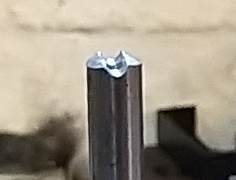 IMG_20200926_163809 IMG_20200926_163809 by malcolm brown, on Flickr And then all that remained was to part the collar off and do it again - 24 times....  IMG_20200926_181759 IMG_20200926_181759 by malcolm brown, on Flickr Th eagle eyed will notice that there are 25 collars here. I thought the chances of losing one were high so made two spares - and then managed to lose one anyway (although it turned up later in the swarf tray on the lathe). In fact, one of them is made of stainless as I ran out of 5/16" BMS just before the end of the job. Quite a lot of work for some small and not very noticeable parts - but by making things in batches I am at least progressing the loco as well as the tender. Malcolm |
|
mbrown
Elder Statesman
Posts: 1,719
|
Post by mbrown on Sept 27, 2020 17:17:12 GMT
Yesterday was enough repetition work for me for a while, so today I returned to marking out and drilling the main frames for the loco. I know where most of the holes should go, but my photographic evidence shows that some of the rivet patterns are a bit odd, so I have tried to reproduce the strange spacings, especially at the rear end where there are stretchers in all directions As shown in a previous post, I made a jig to drill the holes for the horncheeks. I realised that, by turning it upside down it would reach low enough to put in the hornstay holes as well. The pivots for the spring hangers and equalisers also got included on the jig, so all those holes are located identically from each axlebox centre. When I made the cylinders, I made another jig to drill the mating face with the frames - this then came into use again to drill the frames themselves. All the holes are a wee bit undersize so that I can run a reamer through both cylinder and frame to get perfect alignment and I will then turn up some small fitted bolts. Here are the frames and the two jigs.  IMG_20200927_175012 IMG_20200927_175012 by malcolm brown, on Flickr The holes for the steam and exhaust pipes were pilot drilled with the jig then opened out and reamed. The stub pipes on the cylinder slid through perfectly. They will, in due course, project into a smokebox saddle and be sealed with O rings.  IMG_20200927_174909 IMG_20200927_174909 by malcolm brown, on Flickr There are still a lot more holes to drill. Some will be marked off from components on the outside of the frame. There are also stiffening angles along the top of the frame, inside and out, which will need a bit of thought.. That's it for a couple of weeks now. Best wishes all. Malcolm |
|
stevep
Elder Statesman
Posts: 1,070
|
Post by stevep on Sept 28, 2020 16:40:58 GMT
Like the jigs, Malcolm.
|
|
mbrown
Elder Statesman
Posts: 1,719
|
Post by mbrown on Sept 28, 2020 17:58:54 GMT
Many thanks Steve.
One advantage of having a sloping frame gap to take a (dummy) wedge is that the piece of the jig which goes into the horn gap wedges firmly in place and there is no need to clamp the jig - although I used a small toolmaker's clamp for belt and braces. In fact I had to tap it with a hammer to get the jig to come free after drilling.
I am now thinking how I might use the same jig to set up the rear horns in the mill to get the taper in the dummy wedge identical to the slope of the horns.... but that will happen another day.
Malcolm
|
|
mbrown
Elder Statesman
Posts: 1,719
|
Post by mbrown on Oct 10, 2020 18:39:27 GMT
At last a bit of workshop time today. I wanted a simple and light job - my rowing club went back on the river this morning for the first time since mid-March and as a result I am aching in all sorts of unexpected places.... It's great being fit, it's the pain of getting there that is less attractive... I begint o feel I am getting too old for all this exertion. Anyway, I did the spring pins for the tender. I had thought of doing the ones for the loco in the same batch, but today a batch of 8 was much more attractive proposition than a batch of 24. The loco ones can wait their turn, I didn't take photos of the processes. They are lengths of 3 mm rod silver soldered to a block of 5/16" x 5/32" BMS which was then rounded off to 6 mm diameter in the mill to get the right effect where the rod joins the boss.  IMG_20201010_181407 IMG_20201010_181407 by malcolm brown, on Flickr The thread is 3 mm x 3.5 as spring pins usually have a very fine thread and anything coarser looked wrong. This means I have to make my own nuts as I can't find any that size commercially. With two per pin, that means I'll need 48 minimum... I have some 6 BA hex BMS which will be suitable. Which leads to a question. When making my own nuts, I usually tap them in the lathe and then part off from the stock. But this invariably leaves a nasty burr where it was parted which has to be removed, and usually a tap needs running through again. All very time consuming. But if I part off blanks before tapping, I have to set them up true for tapping and facing - which is also a faff. What do others do when making small nuts? Best wishes Malcolm |
|
JonL
Elder Statesman
WWSME (Wiltshire)
Posts: 2,907
|
Post by JonL on Oct 10, 2020 18:42:38 GMT
Personally I do the first option, tap a long thread into hex bar and then part off. Running through with a tap doesn't take a huge amount of time. But what I'm far more likely to do is weigh up the cost of buying some against the time to make and what I could be doing with that time and end up buying 100 and putting the spares in compartmented tray storage in case needed for another project.
|
|
don9f
Statesman
Les Warnett 9F, Martin Evans “Jinty”, a part built “Austin 7” and now a part built Springbok B1.
Posts: 960
|
Post by don9f on Oct 10, 2020 22:20:12 GMT
Hi Malcolm, I also would make my own using your first option.....I think you probably meant 0.35mm pitch?
Cheers Don
|
|


