mbrown
Elder Statesman
  
Posts: 1,786
Member is Online
|
Post by mbrown on Jun 14, 2020 19:13:53 GMT
Not much workshop time available this weekend, but a few more bits done. The bushes for the tender brake shaft are done and fitted, and also the horn cheeks The latter are simply lengths of 1/4" x 1/16" BMS strip rivetted on. The photos earlier in the thread show that this is as per the prototype.  IMG_20200614_171706 IMG_20200614_171706 by malcolm brown, on Flickr To get them parallel and right in line with the frame slots, I used a bobbin turned in BMS which fitted exactly in the frame slot and was kept from falling through by a length of 1/8" silver steel.  IMG_20200614_171744 IMG_20200614_171744 by malcolm brown, on Flickr I also spent some time cutting 5/8" square steel tubing into angles - there are angles on the outside of the tender frames top and bottom and more angles attaching various bits. They scale at a tad under 1/4" and about 18g which, coincidentally is the thickness of the tubing. I forgot to take pictures of this operation, but there are a lot more angles needed, so they will be forthcoming soon. The other development of the day is that I should soon receive a set of etched plates for the loco. I saw a photo on the internet of etched plates for 99 3462 for someone who was building a small scale model and got in touch with the supplier, Beckert Modellbau in Germany. They were able to offer a set at the scale I need (1:9) at a very reasonable price considering what I paid for a pair of oval plates from a UK supplier for the Burma Mines loco. The only drawback is that Beckert can only etch them onto 0.5 mm nickel silver, which is a bit thin - but the prototype plates are on thin aluminium and if necessary I can stick them to backing plates. Anyway, only just over a week from ordering, I had an email to say that they were ready! I will post a picture when I get them. It will be ages before there is a cab, smokebox door etc to fit them to, so I had better make a note of the "safe place" I put them in..... More next weekend, I hope. Malcolm |
|
mbrown
Elder Statesman
  
Posts: 1,786
Member is Online
|
Post by mbrown on Jun 20, 2020 17:32:32 GMT
The etched plates arrived this morning from Beckert Modellbau in Germany. Very nicely done although I suspect they are scaled up from patterns intended for the small model railway market as the hex head bolts are shown raised. No problem, I can either drill them out and use small nuts and bolts or leave them and find another way to fix the plates to the loco. It will be a long time before they are needed, but having seen Beckert's work on the internet, and enquired whether he did all scales, it seemed sensible to order straight away when I got an affirmative reply (in English!). Whether Brexit would make a difference to the ease of ordering (or the price) I don't know, but it also seemed as well to get them before the end of the year. 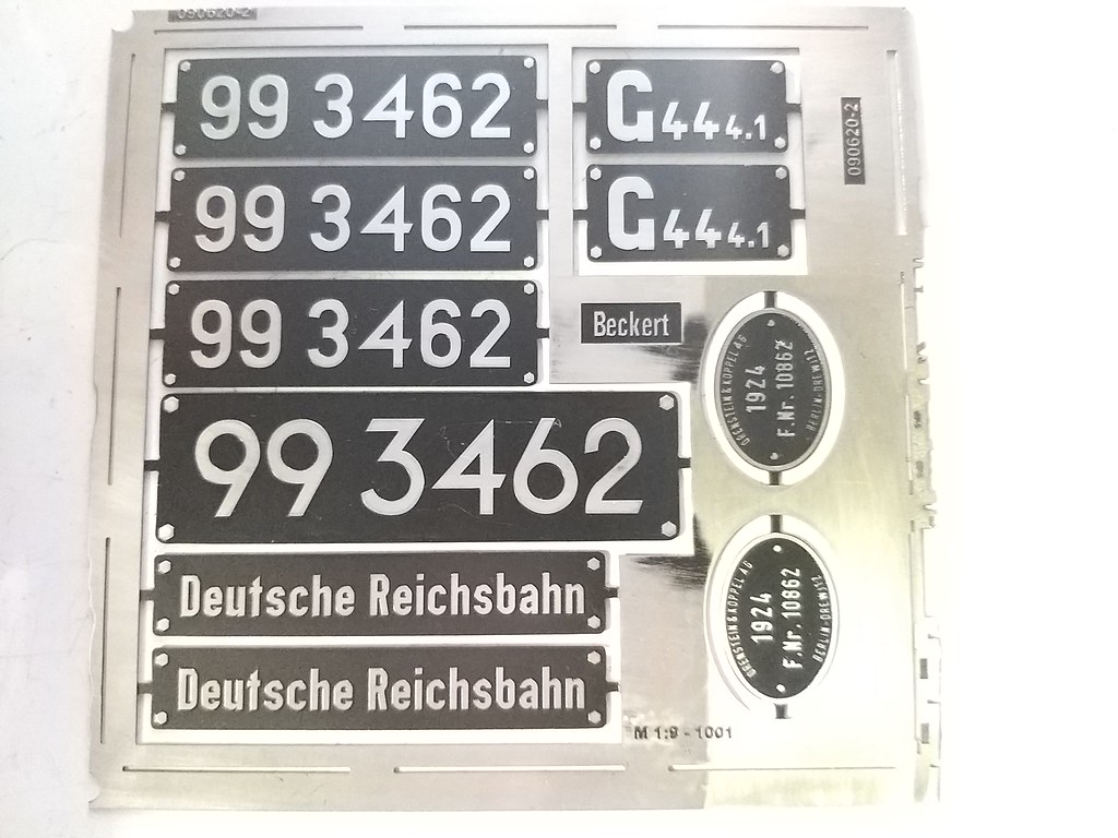 IMG_20200620_140723 IMG_20200620_140723 by malcolm brown, on Flickr They are etched on 0.5 mm nickel silver. The ones carried by the loco today are replicas made by my friend Sven Schlenkrich who cut out all the letters and numerals by hand in aluminium sheet. Old photos show that the plates in the 1960s were also made with numerals etc rivetted onto a backplate. The sheet from which the numerals were cut was quite thin, so the thickness (or lack of) on the etched plates is about right. Oddly, while the number plates, Deutsche Reichsbahn and class plates are spot on, the Orenstein and Koppel builders plates show the wrong number and date - ten years out and a slightly different O&K design!  Bad_Muskauer_Bahn_BR_99_3462..002 Bad_Muskauer_Bahn_BR_99_3462..002 by malcolm brown, on Flickr Not sure why - I have emailed Herr Beckert to tell him, but it doesn't really matter as I shall probably make a pair of more deeply etched plates for to be closer to the original as these were definitely castings. And I doubt if anyone in the UK would notice..... Still, it all feels like progress. Malcolm |
|
mbrown
Elder Statesman
  
Posts: 1,786
Member is Online
|
Post by mbrown on Jun 20, 2020 20:28:31 GMT
This afternoon I made a start of the buffer-couplings which are rather unusual. The picture below shows the front one as it now is after modification for service on the Waldeisenbahn Muskau. In DR times, the buffer head was larger and square and the arms carrying the coupling hook and chains were shorter. The WEM uses a simple link coupling, so the buffer head has been cut down and the link is carried by a single pin with an L shaped safety bar to prevent it riding up But the interesting bit which has been the same all the loco's life is the "spider" arrangements which supports the head of the buffer and embraces a long volute spring.  a2f2091bb00be902b163c956c820afab (3) a2f2091bb00be902b163c956c820afab (3) by malcolm brown, on Flickr I had been thinking about how to make these for some time and so drew these spiders out in CAD and got them laser cut in the flat by MEL. 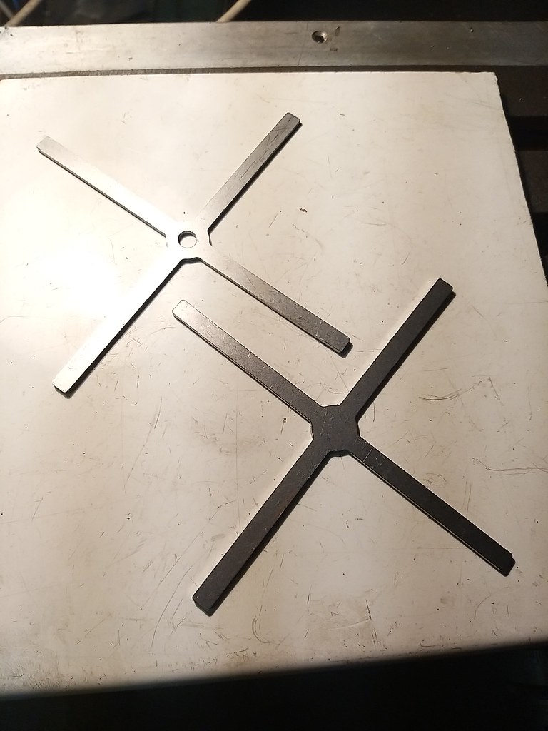 IMG_20200620_153855 IMG_20200620_153855 by malcolm brown, on Flickr To bend them up so that the arms were all the same length, I made a small former - a piece of 3/4" aluminium and an odd chunk of hex bar from the scrap bin. The hex bar was bored 3/4" and four notches filed in it to take the arms of the spider. 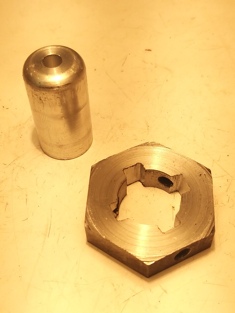 IMG_20200620_154139 IMG_20200620_154139 by malcolm brown, on Flickr The embryonic spiders where then bolted to the former and the legs bent down to fit against it as tightly as possible.  IMG_20200620_154440 IMG_20200620_154440 by malcolm brown, on Flickr Then the hex piece was fitted over the legs flush with the end of the ali former and the projecting ends of the legs bashed down firmly against it so that they were all level with each other. This whole arrangement was then chucked in the 4-jaw and a skim taken off each of the feet so that they were flat to mate against the buffer beams. They were then drilled for the fixing bolts and the ends rimmed and rounded off. 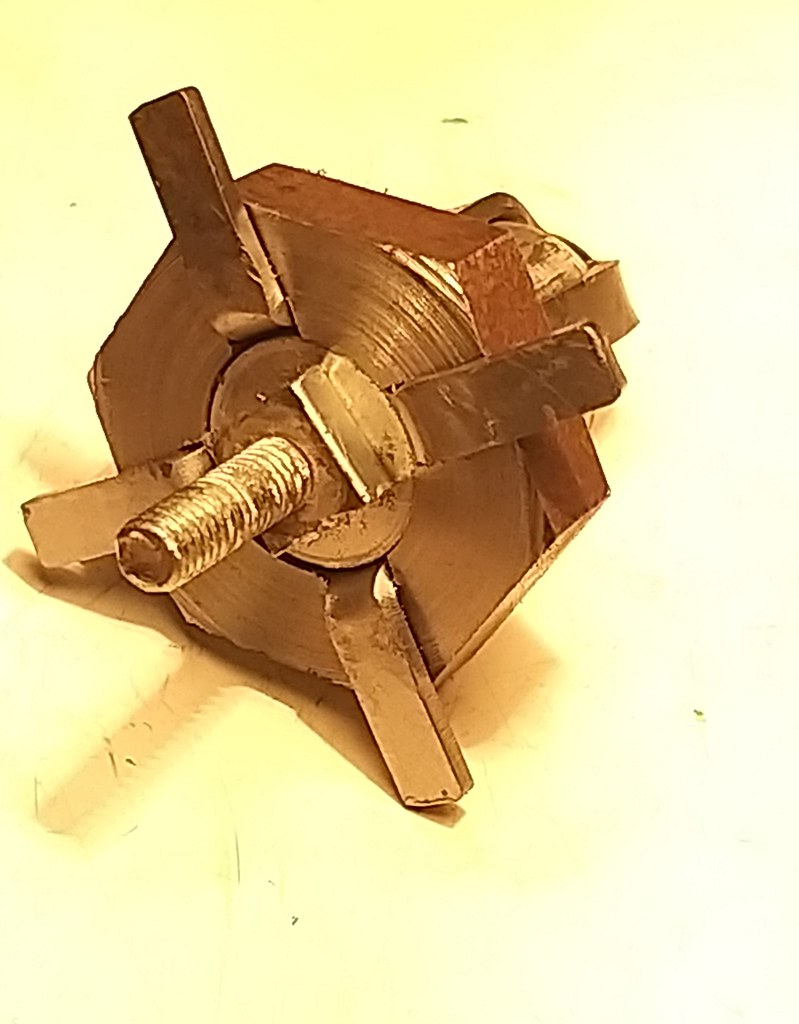 IMG_20200620_155104 IMG_20200620_155104 by malcolm brown, on Flickr On the front buffer, the lower leg has the tab bent inwards, but it was easy to bend it down to meet the inner part of the former which was set level with the outer part. Here they are, fitted with the bosses which are squared 5/16" to take the buffer stem, and sitting on their respective buffer beams. The bosses will be silver soldered in place tomorrow, I hope  IMG_20200620_174215 IMG_20200620_174215 by malcolm brown, on Flickr Before I go much further I shall have to decide if I am going to be modelling the loco in DR days or as preserved - I am inclining to the former, but making the buffer head will be the moment when I am committed one way or the other, so it may have to wait a bit. Maybe tomorrow I will get on with the tender frames instead. Best wishes all. Malcolm |
|
mbrown
Elder Statesman
  
Posts: 1,786
Member is Online
|
Post by mbrown on Jun 21, 2020 17:43:39 GMT
Oh dear! The perils of railway research..... After making the buffer-coupling supports yesterday, I spent part of the evening looking at pictures of the loco in DR days trying to work out the size of the buffer head. Comparing those pictures with some of my shots of her last year, it was evident that, sometime in preservation, the whole front buffer-coupling had been lowered by 2 or 3 inches. That explained why the lug on the bottom leg was turned inwards and not outwards - it enabled that leg to use the original bolt hole, but everything else was lower. It was very neatly done with no vestige of the old holes. But it leaves me with a dilemma if I go for the DR period, as I will need to re-do various bits. I will face that decision another day I did, however, make the volute springs for the buffer-couplers. Both Lyn and the Burma Mines loco have volute springs for the buffers, so I have done this job before - but as volute springs are quite unusual in model engineering, and none of the magazine articles on springs seem to mention them, I thought my technique might be of interest. These are made form 7/16" x 18g spring steel strip. First, a tab is bent over at one end, the bend being at the helix angle of the spring, The bend itself is thoroughly flattened and, if a slight crack appears, so much the better as it needs to be broken out at a later stage.  IMG_20200621_154003 IMG_20200621_154003 by malcolm brown, on Flickr The hole through the centre of the spring needs to be clearance for 1/4", so a mandrel of 1/4" BMS is then prepared with a slot at the end to take the bent piece of the strip.  IMG_20200621_154042 IMG_20200621_154042 by malcolm brown, on Flickr Then the strip is bent around the former. It is heated to red with a small propane flame, with the flame concentrated just on the bit to be bent, and as it gets to red, the resistance of the metal suddenly "gives" and allows it to be bent around in the volute coil.  IMG_20200621_154228 IMG_20200621_154228 by malcolm brown, on Flickr The mandrel is then removed, and the tab that went in the slot is broken off with a pair of fine nose pliers. A small round file can clean up the slightly ragged edge inside the inner coil. Both ends are then ground flat and the final coil ground to a neat end. Then the springs were heat treated buy heating to red and quenching in oil, then tempered to blue.  IMG_20200621_165553 IMG_20200621_165553 by malcolm brown, on Flickr They are pretty stiff - but that is about right for a single buffer. It will be a fairly heavy loco for its size, so a strong buffing spring is appropriate. Today's other work was on the outrigger brackets on the tender frame which take the weight of the tank. One down, three to go - I need to make some more steel angle first.  IMG_20200621_174040 IMG_20200621_174040 by malcolm brown, on Flickr That's it for another week. Malcolm |
|
|
|
Post by steamer5 on Jun 21, 2020 22:44:47 GMT
Hi Malcolm,
Many thanks on the spring how to!
I’ve got a couple of those to make, given how long I’ve been going so far they are likely to be years away, still nice to know how to do it!
Cheers Kerrin
|
|
mbrown
Elder Statesman
  
Posts: 1,786
Member is Online
|
Post by mbrown on Jun 23, 2020 20:41:12 GMT
Hi Kerrin,
What is it that you are building that requires volute springs?
Just interested....
Malcolm
|
|
|
|
Post by steamer5 on Jun 24, 2020 9:54:34 GMT
Hi Malcolm,
A 5” K1 Garratt...... see my avatar.
It’s a VERY slow build.
Cheers Kerrin
|
|
mbrown
Elder Statesman
  
Posts: 1,786
Member is Online
|
Post by mbrown on Jun 24, 2020 14:35:15 GMT
Great project, Kerrin! I considered one in 2.5"g and got the drawings from the Manchester Museum, but the amount of repetition work put me off. I hadn't then discovered CAD and Laser cutting..... I also got the drawings for the Darjeeling Garrett - even more complicated!
Good luck!
Malcolm
|
|
|
|
Post by steamer5 on Jun 24, 2020 18:33:41 GMT
Thanks Malcolm!
I got lucky some years ago, by chance I found 2 gentleman who were building K1’s. One in the UK who was doing the drawings & building to prove them, unfortunately he never finished either, but he sold me a copy of the plans he had done. the other was in Australia who was happy for me to have a large pile of casting done from his patterns, getting them from Australia to New Zealand is another story. I also got a set of microfilm copies of the orginal drawings, another story on getting them printed!.
Now it’s learning CAD enough to get scale drawing done!
Last year we did a trip to Switzerland & I meet up with a gentleman from Germany in Zurich at there model railway & got to look over his 5” model, a great day was spent there!
Cheers Kerrin
|
|
mbrown
Elder Statesman
  
Posts: 1,786
Member is Online
|
Post by mbrown on Jun 24, 2020 19:40:07 GMT
Hi Kerrin,
Do you have Peter Manning's book "The Anatomy of a Garratt" - full of excellent drawings and exploded views of the K1? Well worth having.
Malcolm
|
|
|
|
Post by steamer5 on Jun 25, 2020 9:27:50 GMT
Hi Malcolm, Yes I do! Great book, although I did spot a couple of errors, nothing major but having spent many hours looking over the full size drawings, having said that I would love to have a set of his drawings! I also have the books by Christian Cenac also full of great drawings! I have my youngest son working on some parts for me... 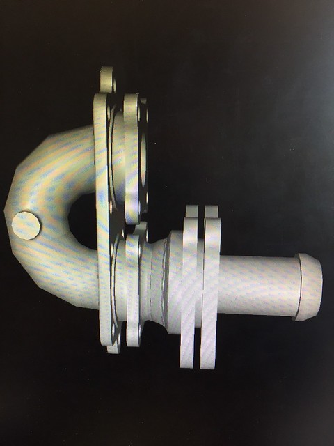 Generated by tools.sportscard.trade Generated by tools.sportscard.trade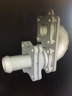 Generated by tools.sportscard.trade Generated by tools.sportscard.trade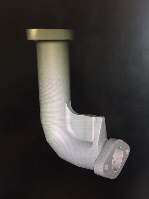 Generated by tools.sportscard.trade Generated by tools.sportscard.tradeHe drafts for a job & said these were some of the toughest parts he’s done...... had nothing to do with needing several drawings to look at at the same time & neededto jump back & forth to find or workout dimensions! I can see some casting arriving on my doorstep some time soon, he’s just got to get them finished! I had the same issue working out the motion brackets, there was no drawing of it just outlines with a couple of base dimension, then had to work out from out her parts the bits that weren’t dimensioned! Was a hair pulling exercise & I don’t have that much to pull out! Cheers Kerrin |
|
mbrown
Elder Statesman
  
Posts: 1,786
Member is Online
|
Post by mbrown on Jun 25, 2020 10:51:06 GMT
Good grief, Kerrin, that is complicated stuff!
How reliant we are on the younger generation.... My stepson (rwilliams of this parish) taught me basic 2D CAD at Christmas and I am enjoying using it, but I couldn't begin to do that kind of 3D stuff your son manages. For complex castings etc. my approach is fabrication - not in your league, but fairly effective. Do post some pictures as your K1 grows - it will be good to compare our respective 2' gauge creations!
Malcolm
|
|
|
|
Post by steamer5 on Jun 27, 2020 10:54:54 GMT
Hi Malcolm,
I think they look worse than what they are, I'm just glad Ive got somebody who can draw this up for me. Like you Ive been playing with 2D CAD for a while & enjoying it. I never did drawing / drafting at school, my first training was with paper & pencils when I did my steam tickets. Ive been using Draftsite & have had to swap to Fusion 3D which is a WHOLE new learning curve!
Yes I will post here... the only issue my progress has fits & starts, with long spells of no progress! I better get on to it or I'll never get to enjoy driving it!
Cheers Kerrin
|
|
mbrown
Elder Statesman
  
Posts: 1,786
Member is Online
|
Post by mbrown on Jun 28, 2020 19:28:11 GMT
Not much workshop time this weekend, but the tender frame is beginning to take shape. The first job was to make some more steel angle by slitting the sides of a length of 5/8" square steel tubing. This was mounted in the mill and a 3/32" slitting saw down the middle of each side left me with four lengths of angle of the right size. The saw being fairly wide (I would normally have used a 1/32" saw) I had to take it slowly, but it worked out fine. I left the square tube intact for about 1/2" at each end and in the middle and that helped it keep its shape as each side was cut. Then it was easy to cut through the tabs with a hacksaw and clean up the rough bits.  IMG_20200627_160711 IMG_20200627_160711 by malcolm brown, on Flickr Then the rest of the time was spent adding angles to the tender frames, along with the spring hanger pockets and the outriggers to take the tender body. I managed to complete one side. The bits for the other side are all ready to rivet or bolt in place. There remain some further angles to add, but some of the rivets for these also hold cross stays on the inside of the frame. I shall probably use round headed screws without slots for these. In fact, some of the fittings in the picture are screws and some rivets - not easy to tell which. 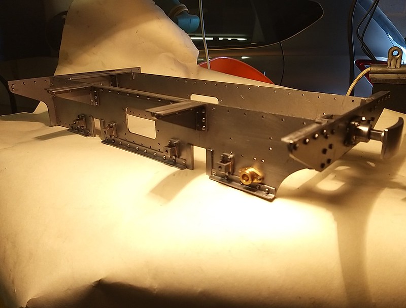 IMG_20200628_193441 IMG_20200628_193441 by malcolm brown, on Flickr The frames are now assembled to the buffer beams, although only with a screw in each corner for now - there are a number of horizontal and vertical cross stays to add which should make for a rigid assembly even though the plates themselves are pretty thin. This seems to have been the O&K philosophy too - thin plates generously braced and stiffened with angles.  IMG_20200628_193505 IMG_20200628_193505 by malcolm brown, on Flickr A couple of the horizontal cross stays are lodged in place to see how they will look when fitted.... I expect someone, someday, will pick me up on the countersunk screws next to the horncheeks….. but there they are on the original, although it would take a big screwdriver to undo them! 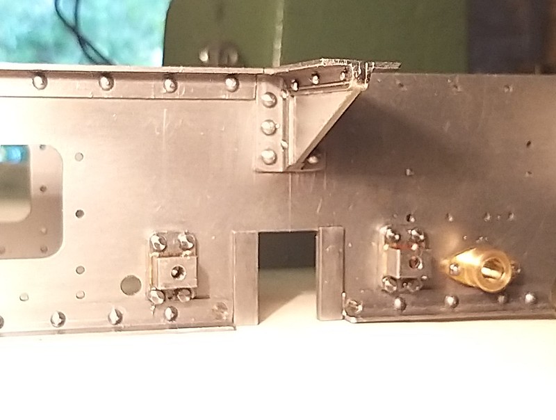 IMG_20200628_194904 IMG_20200628_194904 by malcolm brown, on Flickr  DSC00447 DSC00447 by malcolm brown, on Flickr I mentioned in the earlier post about the etched plates that the builder's plates had the wrong date and works number on them. I wasn't too worried as I thought I might make replacement plates myself, but I told Herr Beckert in case he had future orders for 99 3462's plates. By return, he offered to re-do the plates, in brass as per the DR era original, and send them free of charge. It is always good to be able to acknowledge and publicise good service like that. If anyone on the forum is interested in German railways (DB and DR) the Beckert Modellbau website is a mine of information and his service is excellent. More next week, I hope. Malcolm |
|
mbrown
Elder Statesman
  
Posts: 1,786
Member is Online
|
Post by mbrown on Jul 12, 2020 19:15:55 GMT
The last two weekends have seen plenty of activity in the workshop, all geared to getting the tender frame assembled. It looks fairly advanced in the pictures above but it has taken ages to put in the various cross stays, finish the reinforcing angles and so on. It still needs the two vertical stays in the middle, which form the ends of a compartment in the middle of the frame which is accessed by the doors on either side. So as well as the vertical stays, it needs a horizontal one to act as the base plate.
That will have to wait until next weekend - assuming I get any workshop time.. Now that lockdown is easing, the grandchildren are coming to stay. They're too young to "help" in the workshop, although the five year old has inherited the battery electric loco I made for his father when he (the father) was 8 years old, and seems to be getting the hang of driving, so maybe in a few years he can join me for some apprentice tasks!
But assembling, dis-assembling and re-assembling the tender frames for each operation is tedious - and I have sometimes found myself taking 15 minutes or more to get a recalcitrant nut started on an inaccessible bolt ….. It will be good to switch to something different soon.
More next week, all being well, with pictures!
Malcolm
|
|
mbrown
Elder Statesman
  
Posts: 1,786
Member is Online
|
Post by mbrown on Jul 19, 2020 20:19:41 GMT
This weekend saw the tender frames more or less finished. They still need axleboxes, springs and spring hangers and the rear buffer-coupler has to be finished, but the basic frame is there.  IMG_20200719_195814 IMG_20200719_195814 by malcolm brown, on Flickr The underside shows some of the stretchers and the coupler pocket made earlier.  IMG_20200719_195901 IMG_20200719_195901 by malcolm brown, on Flickr Here at the front end the buffer and the safety chain brackets are all fitted.  IMG_20200719_195849 IMG_20200719_195849 by malcolm brown, on Flickr The many stretchers, vertical and horizontal are typical of the German style of frame building. The original uses surprisingly thin plates - mainly about 1 cm thick - although I have beefed mine up to 2 mm or 2.5 mm for the frames, buffer beams and the middle cross stays, and 1.5 mm for the horizontal stretchers. Tjis is both for rigidity and weight. 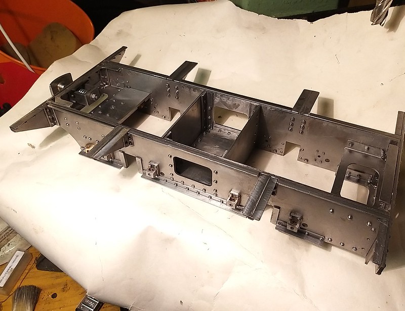 IMG_20200719_195931 IMG_20200719_195931 by malcolm brown, on Flickr The vertical and horizontal stretchers in the middle create a kind of cupboard between the frames. The rectangular openings in the frame will have hinged doors. On the prototype, all sorts of junk seems to live in there.... but there's not much point making miniature buckets, tools etc, if they're going to be hidden away under lock and key!  IMG_20200719_195821 IMG_20200719_195821 by malcolm brown, on Flickr That's it for a few weeks now - I am busy next weekend and then on leave for a while. The Talyllyn is running trains again from 1st August and I have managed to get a few driving turns in the subsequent weeks. It is all going to be very unusual with the various Covid-19 precautions in place. Drivers and Firemen are to stay on their own sides of the footplate and sanitise their own equipment. Maybe, like the old drivers of legend, I shall have to chalk a line down the middle of the cab! If you are in Mid Wales this summer do come and have a ride (booked in advance only) - having lost the best part of the season, the railway really needs support. Best wishes Malcolm |
|
|
|
Post by Deleted on Jul 19, 2020 23:13:07 GMT
That's some lovely neat work there Malcolm...very nice sir
Pete
|
|
mbrown
Elder Statesman
  
Posts: 1,786
Member is Online
|
Post by mbrown on Aug 1, 2020 18:04:46 GMT
The drawbar on the prototype is in two parts, joined with a turnbuckle and locknuts. You can just see it under the tender buffer beam here:  DSC00487 DSC00487 by malcolm brown, on Flickr The drawbar scales at almost exactly 1/4" dia and, by chance, I happened upon these two 1/4" UNF eyebolts in my draw of "things that night come in useful one day". The holes through the eye are a bit over 1/4" - and that's no problem at the tender end where an oversize pin can be used, but at the loco end the drawbar hole is clearly a slot so that there can e a bit of relative movement between the loco and tender, taken up by the buffer.  IMG_20200801_163900 IMG_20200801_163900 by malcolm brown, on Flickr  DSC00513 DSC00513 by malcolm brown, on Flickr I wanted to keep the strength of the eyebolt but get a 3/16" slot in one of them, so I put a piece of 3/16" steel in the hole...  IMG_20200801_164531 IMG_20200801_164531 by malcolm brown, on Flickr ….then heated the end to bright red and gave it a firm wallop with a hammer on the anvil end of the vice and, on withdrawing the steel plug, the end result was just right. Here it is joined to the other one with a threaded sleeve and locknuts.  IMG_20200801_174604 IMG_20200801_174604 by malcolm brown, on Flickr Of course, the prototype would have had left and right hand threads in the turnbuckle - and this is undone to part the loco from the tender. The threads on the eyebolts are both RH. But as the pin at the loco end is easily accessible through the cab floor (or at least, I hope it will be....) I didn't see the need for the turnbuckle to be undone. When I know the exact length, I can set it and Loctite or pin the threads so there is no chance of them vibrating loose. Here it is, with the tender pin in place.  IMG_20200801_181049 IMG_20200801_181049 by malcolm brown, on Flickr I am waiting for materials to arrive before attempting the tender axleboxes, but may make a start on some of the loco components instead.... Best wishes all. Malcolm |
|
timb
Statesman
 
Posts: 512 
|
Post by timb on Aug 2, 2020 13:34:49 GMT
Outstanding Malcolm, this really is coming along at a rate of knots! Have you created a full set of drawings or is it a draw as you go?
Tim
|
|
mbrown
Elder Statesman
  
Posts: 1,786
Member is Online
|
Post by mbrown on Aug 2, 2020 15:37:11 GMT
Hi Tim, No, I don't really do drawings for most of it. I always do a layout of the frames on the drawing board to get centres and clearances set out from the start, otherwise I either scale down a GA of the prototype or (in this case) do sketches based on the measurements and photos I took in Germany last summer. Here is a page from my file of "field drawings" (complete with oily fingerprints) - in this case the tender frame, along with the spring and spring hanger bracket.  IMG_20200802_162453 IMG_20200802_162453 by malcolm brown, on Flickr I then did another sketch using my collection of photos to put in as much of the detail as possible that I didn't have time to get during the visit, guesstimating dimensions as far as possible.  IMG_20200802_161542 IMG_20200802_161542 by malcolm brown, on Flickr Now that I have begun to master 2D CAD, I then drew it out in LibreCAD using these dimensions and got the frame laser cut by MEL. I am enjoying CAD but I am only using it for parts that are either complex and time-consuming to cut out by hand or involve a lot of repetition work. When it comes to assemblies, I find I can usually envisage how it all goes in my head and then put it together accordingly. I do, of course, get the odd glitch - in this case the bottom of the coupler pocket on the tender is going to foul the brakeshaft by a few thou when the latter is fitted - you can see what I mean in the picture below.  IMG_20200719_195849 IMG_20200719_195849 by malcolm brown, on Flickr It is remediable, by turning the boss on the pocket to a slightly smaller diameter - but it is annoying as the boss was to scale, so something else much be slightly out. I didn't have enough time under the loco to see if the clearance here was on the tight side. No doubt there will be quite a few more such snags before it is done... Best wishes Malcolm |
|
 IMG_20200614_171706 by malcolm brown, on Flickr
 IMG_20200614_171744 by malcolm brown, on Flickr


