JonL
Elder Statesman
   WWSME (Wiltshire)
Posts: 2,990
|
Post by JonL on Nov 15, 2020 9:54:46 GMT
How very true. I sometimes feel a bit inferior to those who go to the nth degree for perfection, but we are all in this hobby for different things, and yet the same thing, our own satisfaction and enjoyment.
|
|
|
|
Post by Roger on Nov 15, 2020 14:30:15 GMT
How very true. I sometimes feel a bit inferior to those who go to the nth degree for perfection, but we are all in this hobby for different things, and yet the same thing, our own satisfaction and enjoyment. I don't think it matters what level of perfection you aim for, it's an entirely personal decision, largely determined by what equipment you have available. There will always be someone we look up to and wish we could do it to another level. That's just life. Personally I just like to see people making things that make them happy. Creating something, anything, from raw materials is one of life's greatest pleasures, whether that's cooking, needlework or any of the many branches of Engineering. When you consider the other option of making absolutely nothing, life is made immeasurably more enjoyable for being creative. Better still, you get to share each others creations here, at clubs and at shows. It doesn't get much better than that. |
|
mbrown
Elder Statesman
  
Posts: 1,790
|
Post by mbrown on Nov 15, 2020 18:11:43 GMT
The high wind last night blew the roof of the garden shed, so most of today's daylight hours were spent getting it back on and fixing it down better... I did manage a couple of hours in the workshop and finished the eight spring hanger brackets needed for the loco. Exactly the same as the eight made some time ago for the tender, but a batch of 16 felt just too much at the time! 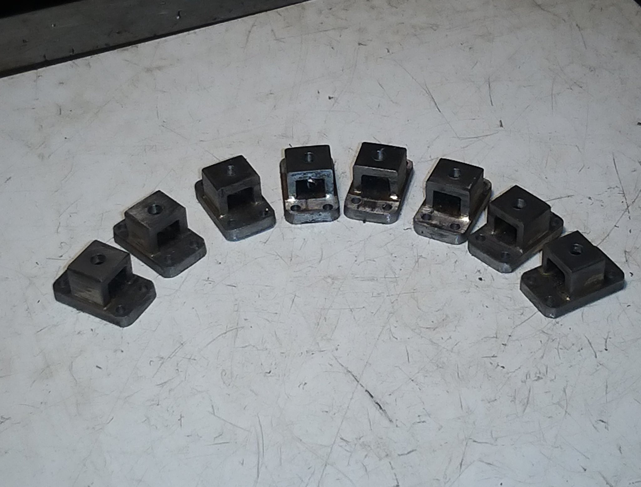 IMG_20201115_163758 IMG_20201115_163758 by malcolm brown, on Flickr That's it for another week - there are still a few more brackets to make and then the next job will be fitting all the horns and finish-machining their working faces. I shall spend odd moments during the week working out how best to hold the frame son the mill.... Best wishes all. Malcolm |
|
|
|
Post by Deleted on Nov 15, 2020 18:19:44 GMT
I did manage a couple of hours in the workshop and finished the eight spring hanger brackets needed for the loco. Exactly the same as the eight made some time ago for the tender, but a batch of 16 felt just too much at the time! Malcolm Oh how I'm with you on that one Malcolm...I hate repeditive work and on 4472 there were 32? Pete |
|
mbrown
Elder Statesman
  
Posts: 1,790
|
Post by mbrown on Nov 21, 2020 18:21:12 GMT
Finished the last two brackets which attach outside the frame today. Actually, there are four more brackets each side which support the running boards, but I don't have dimensions for them and will fit them to place. The ones I am doing at this stage are more critical because the fixing bolts also secure stretchers between the frames, so the positioning is critical. Here's the RH bracket on the full size loco. The oval slot lines up with the one in the motion bracket and the drain cock rod passes through it For some reason, the LH bracket has a much larger cut out, as below, although I have no idea why as nothing has to go through it on that side.  DSC00428 DSC00428 by malcolm brown, on Flickr You can see how the angles fixing it to the frame are joggled to fit around the angle along the top edge of the frame. I couldn't do this by blacksmithing in such a small size, so I did it with separate bits of angle. The top section was only about 3/8" deep so there was only room for one rivet - I therefore silver soldered all the joints. These brackets carry the weighshaft bearings which are mounted above the running board. Weigh shafts can take a fair old pounding, so I wanted everything to be firm. In the prototype picture, t he unpainted nut coming through from the top secures one end of the weighshaft bearing. Here they are after a coat of zinc primer.  IMG_20201121_180222 IMG_20201121_180222 by malcolm brown, on Flickr Today's other job has been to continue fixing the horns to the frames. This is taking longer than expected as the angled horns were made a touch too long and are each having to have a shave taken off the bottom. But I hope to finish that job tomorrow. Best wishes Malcolm |
|
mbrown
Elder Statesman
  
Posts: 1,790
|
Post by mbrown on Nov 22, 2020 18:50:19 GMT
Several hours' work today and not as much progress as I had hoped since it took all afternoon to fix the horn cheeks to the frames. Each one needed much more fitting than I had anticipated. But with the accuracy of the openings in the laser cut frames, and the consistency of the horn cheek thickness as they were made from stock steel strip, the result is that they seem pretty accurate. The acid test will be when the frames are bolted together and I can see if the two sides are mirror images of each other. My intention had been to mount them together on the mill and take a skim off each face with an end mill to ensure absolute accuracy, but I am wondering if I can manage with a less aggressive finishing method. I will experiment next weekend and report back... But here are the frames with their horn cheeks permanently fitted. Each has four 8 BA bolts and there is a smear of medium strength Loctite where they abut the frames, so I doubt if they will work loose in service. I couldn't resist placing a cylinder, motion bracket and weighshaft bracket in place to just to convince myself I am making progress! 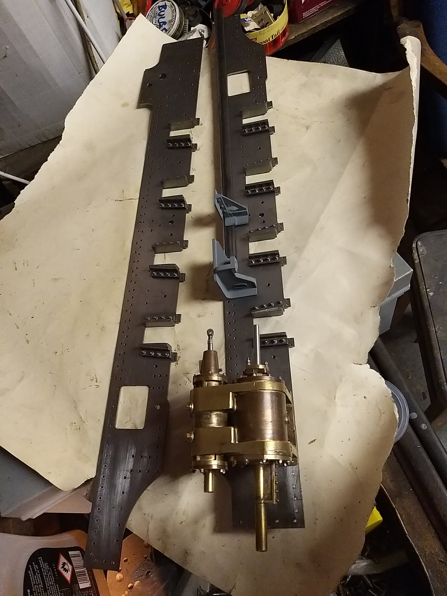 IMG_20201122_183118 IMG_20201122_183118 by malcolm brown, on Flickr Near the end of the job, I was reflecting that my 8 BA tap had cut the equivalent of an 8" deep hole today - at which point it broke! I got the broken stub out after a bit of wangling - but the moral is never to relax your concentration while tapping - even to daydream about tapping! Best wishes Malcolm |
|
|
|
Post by coniston on Nov 22, 2020 19:40:48 GMT
Those brackets look so realistic, I like the fabrication method rather than cast. It looks in the photo of the original that the joggle may well be a bit welded on rather than blacksmithing so your brackets are accurate to prototype.
Chris D
|
|
mbrown
Elder Statesman
  
Posts: 1,790
|
Post by mbrown on Nov 28, 2020 18:17:12 GMT
Yesterday a parcel arrived from Geoff Stait at GS Model Supplies down in Somerset. He offers a water jet cutting service and I needed some parts that couldn't be done by laser cutting but which would be very tedious, and less accurate, to do by hand. While I was at it, I added a number of other bits and bobs that could have been done by laser to the order, as I wanted to compare water jet cutting with the parts I had had already from MEL. It took quite a long time between ordering and delivery, but here they are.  IMG_20201128_145815 IMG_20201128_145815 by malcolm brown, on Flickr The pieces cut from thin plate are as accurate as laser cutting - I can't do a direct comparison on cost, but I suspect they were a wee bit more expensive, but not much. The bits I was especially pleased with were the horn stays and spring buckles which are rather too fine in relation to the thickness of material to have been done easily by laser. These came out very well and will just need a bit of cleaning up with a file. 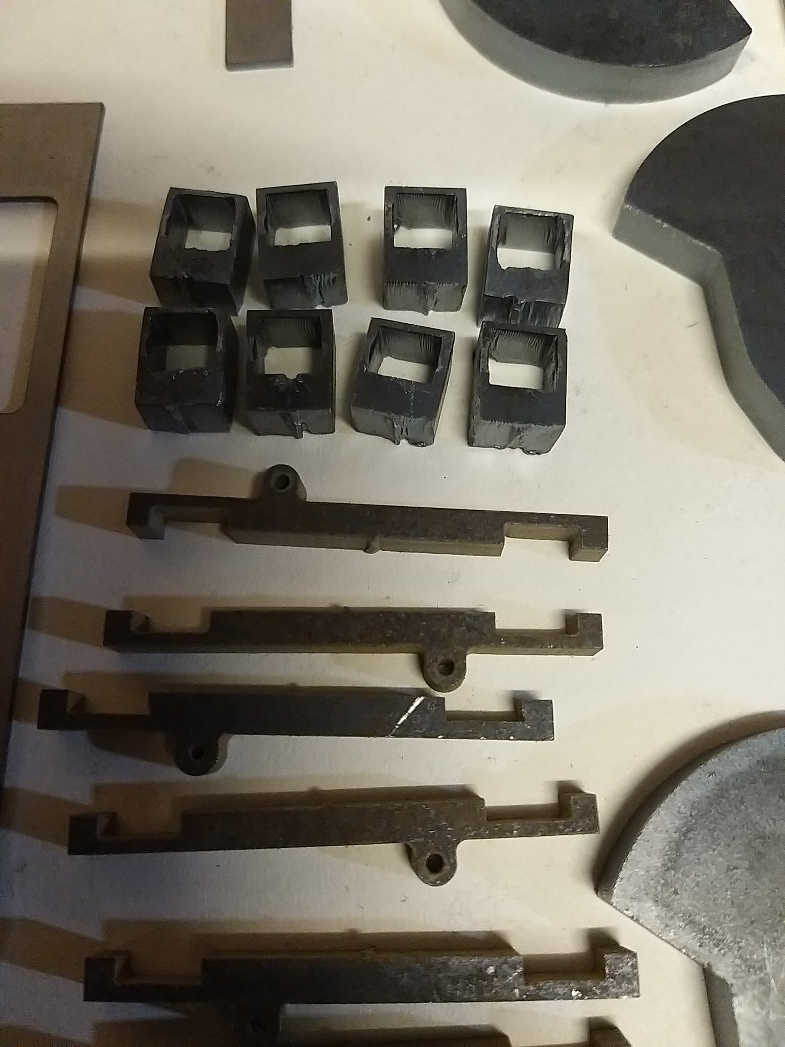 IMG_20201128_145846 IMG_20201128_145846 by malcolm brown, on Flickr Anyway, these all go into the box of bits ready for later stages of the build. Today's job was machining the horns true. First off, I took a length of 3" x 2" box section steel and set it up on the milling table, clocked true.  IMG_20201128_161528 IMG_20201128_161528 by malcolm brown, on Flickr Then the frames were bolted together with spacing plates between them (because the horns and bolts protrude a bit on the inside) and clamped up to the box section. Only one clamp is shown below so that the cutter etc. is visible. Using the DRO on the X axis, it was simple to true up the rear horn for the first axle, then do the next at precisely 89 mm distance, and so on, reversing the process coming back as I did the front horns. I have thus ended up with horns exactly true to each other, square to the frames, 89 mm apart and the same width across the axlebox slot.  IMG_20201128_163153 IMG_20201128_163153 by malcolm brown, on Flickr The long series 3/8" end mill was nice and sharp, so with small cuts the surfaces came out pretty smoothly. The residual cutter marks were taken out by draw filing with a dead smooth file, then the faces were polished with fine emery sticks. I will be making the axleboxes from cast iron, so it should end up as a very hard wearing combination. Best wishes Malcolm |
|
mbrown
Elder Statesman
  
Posts: 1,790
|
Post by mbrown on Nov 29, 2020 19:12:12 GMT
Today, I felt like a change from working on the frames so had a go at the steam brake cylinder. This will be easier to fit before the frames are erected. Here is the full size one. The steam feeds in at the side, below is the drip valve. The thin pipe at the back leads to a pressure gauge in the cab. The heavy pipe across the front is the injector water feed with a take-off from it for flange watering.  DSC00432 DSC00432 by malcolm brown, on Flickr I started with a length of 1.25" cored bronze bar. After turning it to the diameter of the flanges, I put in two flat-bottomed 1/4" blind holes for the bosses to take the stem feed and the drip valve, as these cut into the flange.  IMG_20201129_144410 IMG_20201129_144410 by malcolm brown, on Flickr Once the bore was finished, the rear end was recessed for an end plate which was to be silver soldered in. On the prototype, there is a blind boss on the back cover, presumably an alternative entry point for the steam when the casting was used on other locos. Bosses tapped 3/16" x 40 were pressed into what remained of the blind holes.  IMG_20201129_151919 IMG_20201129_151919 by malcolm brown, on Flickr The mounting flange was made up from odd bits of brass then the whole lot was silver soldered together. The end cover was a simple turning job from the remains of the cored bar. It has a small drain hole to clear any condensate that gets past the piston. The piston has a long trunk which bears in the cover. This will carry the piston rod in due course.  IMG_20201129_181655 IMG_20201129_181655 by malcolm brown, on Flickr And here are the bits assembled temporarily. I ran out of time to fit the cover studs and make the piston rod, so these will be jobs for next weekend.  IMG_20201129_181732 IMG_20201129_181732 by malcolm brown, on Flickr To be continued.... Malcolm |
|
mbrown
Elder Statesman
  
Posts: 1,790
|
Post by mbrown on Dec 5, 2020 19:33:48 GMT
Finished off the steam brake cylinder today (all except the drip valve and the union nipple, but they will wait until things have been erected and they are less likely to get bumped). The piston rod is turned from rectangular BMS and screws into a 5/16" stainless steel ball which is held captive in the piston with a screwed plug. The two flats on the plug are simply because I didn't have any suitable hex rod, and it is unlikely to need to be undone often, if at all. 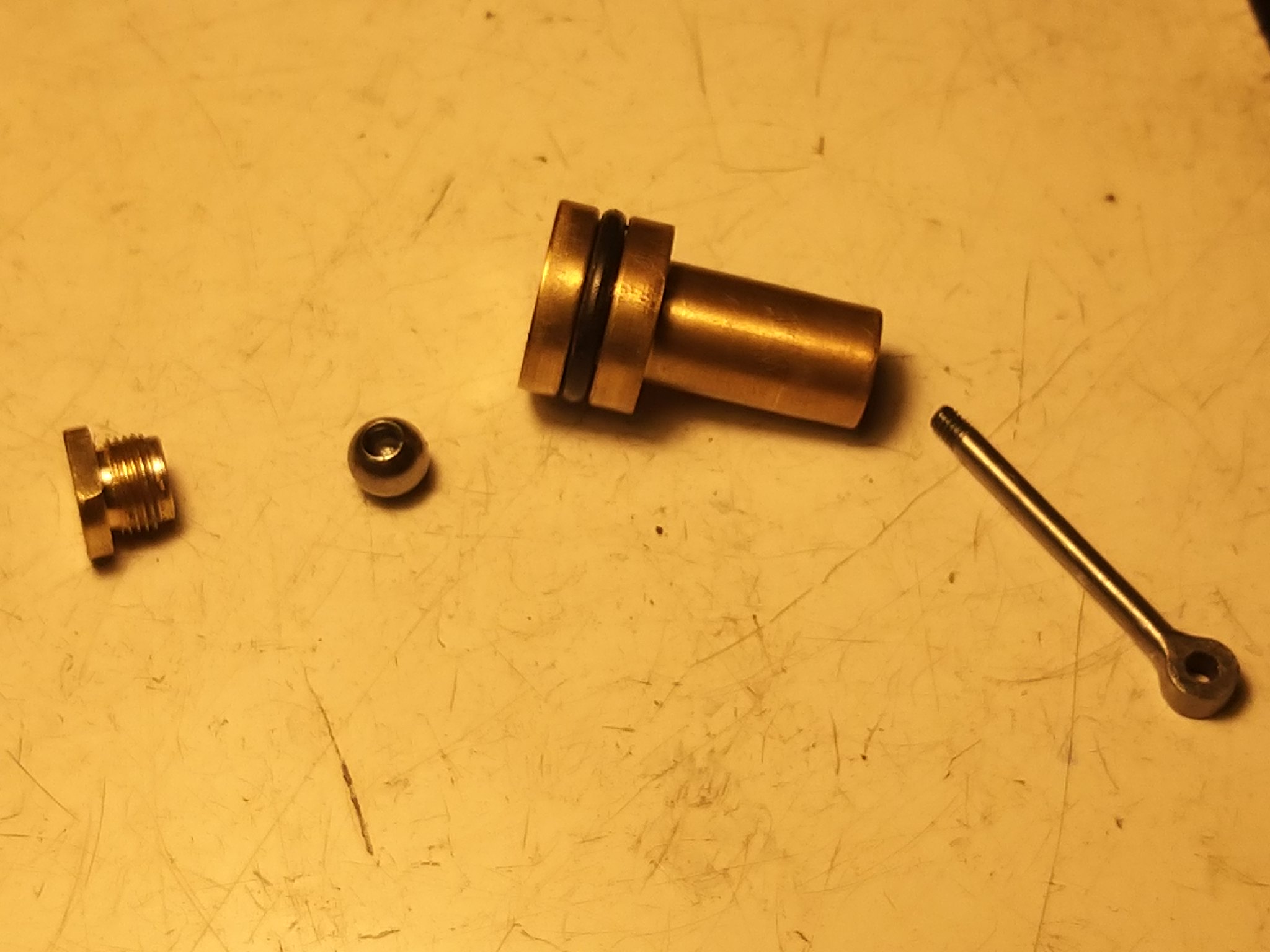 IMG_20201205_154045 IMG_20201205_154045 by malcolm brown, on Flickr And here it is , assembled with the studs for the cover.  IMG_20201205_160952 (1) IMG_20201205_160952 (1) by malcolm brown, on Flickr ... one stud is a wee bit long, I see. That will be trimmed tomorrow. Today's other job was to begin the long task of attaching various bits and bobs to the frames - spring hangers, equaliser pivots, brake shaft bearings, and the motion plates. Then there are the long angles along the top. I have made a start and will see how much I can get done tomorrow. It means an awful lot more 8 BA holes and 2 mm rivets... Malcolm |
|
mbrown
Elder Statesman
  
Posts: 1,790
|
Post by mbrown on Dec 6, 2020 17:48:34 GMT
It's all very well making lots of bits and pieces - sooner or later they have to be erected onto the loco.... A long session today saw the spring hanger pockets, equaliser pivots, brake shaft bearings and one motion plate erected and the top angles on one frame tacked in place with the first few rivets. Lots more rivets and bolts to go, but progress. One cylinder and the other motion bracket are lodged in place here, as is the steam brake cylinder. Then when the hornstays and brake hangers are fitted, I can start erecting the frames, buffer beams and stretchers.  IMG_20201206_171853 IMG_20201206_171853 by malcolm brown, on Flickr More soon, I hope. Malcolm |
|
mbrown
Elder Statesman
  
Posts: 1,790
|
Post by mbrown on Dec 12, 2020 21:06:54 GMT
All those rivets take an age to put in, so I tend to do them a few at a time and then seek light relief in a more interesting job. So today, I decided to finish the loco buffer beams.. only to realise that this also involved a lot of 5/64" rivets too.  IMG_20201212_180330 IMG_20201212_180330 by malcolm brown, on Flickr All the rivets on the front buffer beam hold angles on the back - either for securing the frames or for stiffening - as well as the doubler plate on the front. The four unfilled holes are taken from the prototype and appear to be completely redundant - they aren't evenly positioned either. They seem to have appeared in the early 1960s so I included them - and one day I may find out what they were for. The odd hole at the top of the left hand side of the front beam (RHS as you look at i there) is for a hook to hang up the coupling chain. Malcolm |
|
mbrown
Elder Statesman
  
Posts: 1,790
|
Post by mbrown on Dec 13, 2020 20:54:46 GMT
Today, it is exactly a year since I started cutting metal for the 99 3462 project. The pictures below show how far I have got in 12 months. Cylinders complete Loco frames, buffer beams, horn guides, motion brackets etc., spring hangers and equaliser pivots. Driving wheels (the over-long axle below is just a temporary measure!) Tender chassis almost complete Plus some odds and ends like the steam brake cylinder, buffer supports, coupler pocket and tender handbrake. I also have a lot of laser and water jet cut parts. Lockdown has helped, of course, by curtailing most of the other activities that usually have to be fitted into weekends and holidays. I reckon I have put in an average of seven hours a week plus a bit extra in the Christmas and Easter holidays.  IMG_20201213_180603 IMG_20201213_180603 by malcolm brown, on Flickr Once the frames are erected, it will start to look more like a loco. At present, the front buffer beam is lightly clamped in place. There are actually quite a few more bits to attach to the frames before they can be erected - and a fair number of rivets still to add to the top angles.  IMG_20201213_180720 IMG_20201213_180720 by malcolm brown, on Flickr Malcolm |
|
mbrown
Elder Statesman
  
Posts: 1,790
|
Post by mbrown on Dec 19, 2020 19:04:26 GMT
On to the horn stays today. These are like the later LMS/BR ones in that they clip onto downward extensions of the frames. They also have a small lug on them which carries the adjusting screw for the horn wedges. I had the basic shape water-jet cut and they came out very nicely. I left the gaps which fit onto the frame extensions a wee bit small to take account of the slight draught which the water-jet cutting processes can produce. First, they were draw-filed all over to remove mill scale and the slight marks from the cutter. The lug was machined down in the mill to the correct thickness, and t he pilot hole for the adjusting screw was drilled out and tapped 8 BA. IMG_20201219_150157 IMG_20201219_150157 by malcolm brown, on Flickr Next, each was fitted to its proper location on the frame. I found that a few stokes of a fine fine, to make the gaps parallel was all that was needed - the horn stays then fitted so snugly that they held up against their own weight, but with no forces distorting the frames. (It isn't obvious from the photo below, but the frame is being held up some inches off the bench). 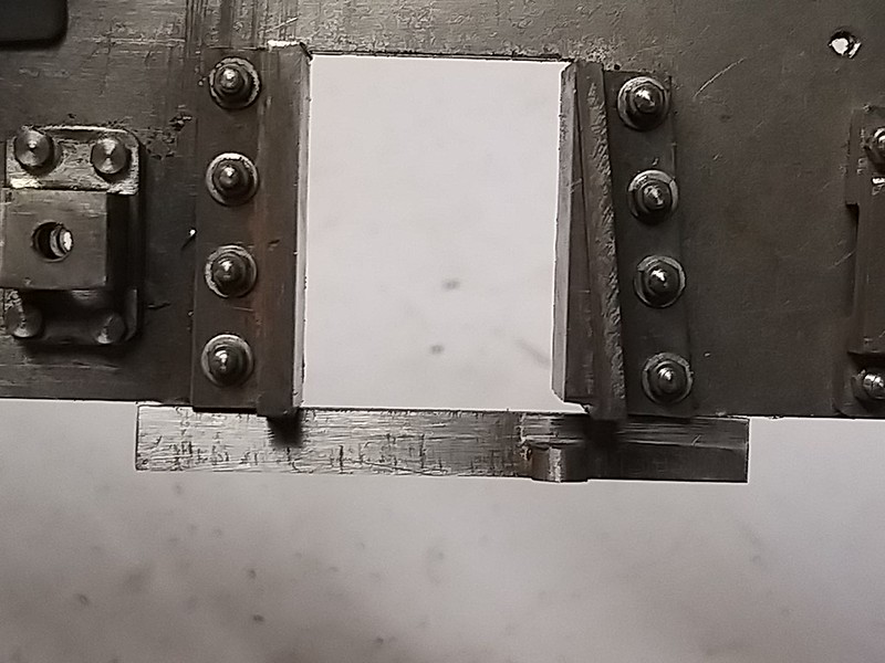 IMG_20201219_154452 IMG_20201219_154452 by malcolm brown, on Flickr They were then drilled for the horn stay bolts and a dummy adjusting screw with a square head fitted to bear against the dummy wedge. I only did this on one horn stay so that I could see the effect - the screws will be vulnerable until much later in the build. There should really be a half nut on the top of the horn stay as well as the full nut under it, but that can wait until a final assembly. 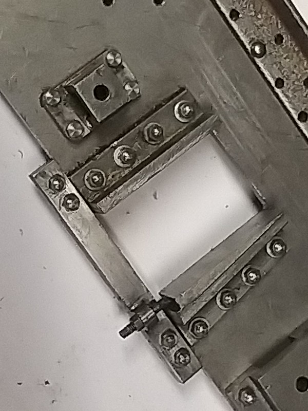 IMG_20201219_163257 IMG_20201219_163257 by malcolm brown, on Flickr Back to riveting the top angles tomorrow, I suspect - you can see the holes I still have to fill.... Malcolm |
|
mbrown
Elder Statesman
  
Posts: 1,790
|
Post by mbrown on Dec 20, 2020 12:58:05 GMT
One of the things I enjoy most in modelling a specific prototype is researching all the details. With "Lyn", there are many hundreds of photos of her throughout her only-too-short life on the Lynton and Barnstaple. Close inspection showed an amazing number of changes over the years and, by comparing the changes to the known dates of overhauls, it was possible to say roughly when they had been made. The Burma Mines loco, having disappeared from view soon after being built, was a bigger problem, and despite following up as many leads as I could find, almost no information was forthcoming.
As 99 3462 is still in existence, I imagined the task would be easier. I was wrong. Because of the obsession with security on the East German railways during the Cold War, there are a fewer photos from the 1945-1969 period than one would expect for a UK prototype, but new ones crop up on the web or on ebay from time to time. They show considerable changes to things like pipework, and many other small details, around the early 1960s, and several inexplicable detail changes after that. For instance, the front guard-angle under the buffer beam usually faced one way, but was turned around in about 1968, then back again! No idea why.
When she was repatriated to Germany in 1978, she had her first rebuild in preservation. Since then, there have been an considerable number of changes further - the tender pipework, altered in the late '70s, was changed again soon after. The steam brake valve in the cab seemed to be the original for a few years, then changed to the present, quite different arrangement (the pipe work gives this away). The heavy German standard water gauge gave way to a modern Klinger one. The couplers were changed and lowered and, at some stage, she received not only a new smokebox (without rivets) but a completely redesigned smokebox saddle too.
For various reasons, I have decided to build the model to represent her in later DDR condition. There are many small reasons for this - the steam heat piping can be used for a vacuum brake system, the water valves on the tender, removed in preservation, will be ideal for the injectors, and (emotional factor only!) I just think she looked better then.
One thing I learned when researching "Lyn", and trying to find out about the Burma Mines loco, was that it pays to follow up leads as soon as you can. Several times I discovered people who held information, only to find that they had recently died or that their archive had been sold and the buyer was unknown. So I have been trying to follow up questions about 99 3462, even if I won't need the information for ages.
So the purpose of this post is really to acknowledge the amount of freely-given help I have received already. Very few photos show the layout of the cab fittings in DDR days, so this has been one avenue of enquiry. I found a photo on the web, taken when she was in store at Boston Lodge in 1974, which, tantalisingly, showed a great deal of detail but was too blurred to make much out. I managed to contact the site owner who sent me a copy with much better definition which I have been able to blow up and make out bits and pieces - although they still need a lot of interpretation and many questions remain!
I mentioned the changed brake valve. The Dampfkleinbahn Muhlenstroth, where she lived immediately after the first restoration (and to where she recently returned) weren't very helpful, but a very similar loco, also an Orenstein and Koppel from the MPSB, now lives at the Hesston Steam Museum in Indiana, USA, although converted to air braking. I contacted them via their website and got a really helpful reply within hours promising to look out some photos and maybe locate the original brake valve as soon as they have access again (they are closed temporarily due to Covid-19).
And I had fantastic help from the lads at the Waldeisenbahn Muskau when I made my trip there to measure her up in 2019.
So this is just to say that railway research has a fascination of its own, and that the help one gets from the steam fraternity around the world is amazing. I am indebted to them all.
Malcolm
|
|
mbrown
Elder Statesman
  
Posts: 1,790
|
Post by mbrown on Dec 22, 2020 18:10:29 GMT
One area where I am going to have to depart completely from the prototype is between the cylinders. On the big engine, there is a complex arrangement of horizontal and vertical stays to give rigidity, and the steam and exhaust pipes are connected to the smokebox by flanged elbows. Out of scale fingers just couldn't get in there. So, whilst mine will look like the real thing where the bits show, I am going to make a fabricated box stretcher to go between the cylinders, with the steam and exhaust elbows brazed in and with a flat top to mate against a flat bottom attached to the smokebox. But, as the steam and exhaust connections come quite high up, I worked out that there was space for a pump underneath, driven from the front axle, with the water connections accessible from the space behind the front buffer beam. The other axles are too close together to fit in a pump drive without severe angularity. The disadvantage will be that the pump is driven via two sets of coupling rods, but if I make those properly, it should be OK. As I mentioned on other threads, my experience of injector-only boiler feed in this small scale is that it is great when they work well but horrendous if, for some reason, they don't. So I am going for a pump and either one or two injectors, plus a hand pump in the tender. Another reason for modelling her in DR days, is that the feed from the pump can use the pipe that fed the front steam-heat connections, and the water line to the pump can run through the pipe that, in full size leads water to the front flanges for lubrication which is clipped to the bottom of the frame stretchers. So, to make a start, I did the eccentric and strap. Space around the front axle is limited, so I used the strap casting for the 3.5"g Tich which has the lugs at 45 degrees. Surprisingly, LBSC doesn't show any provision for oiling the pump eccentric on Tich, but I have added an oil cup as shown. Because my axles will be 1/2" dia instead of 3/8" the throw is a little less, but I am going to have a 7/16" dia ram which should be ample. Here is the eccentric and the first parts of the fabricated pump body.  IMG_20201222_170658 IMG_20201222_170658 by malcolm brown, on Flickr The chamber is from 3/4" dia gunmetal, the valve box from a bit of cast gunmetal intended for Tich axleboxes, and the bolting flange from 1/8" brass. The larger diameter behind the bolting flange will fit snugly in the frame stretcher and the reduced diameter behind it will allow the pump to be unbolted then dropped down to remove it if necessary. Here are the bits waiting to be silver soldered together - which will have to wait for tomorrow as it is now too dark to see my brazing hearth.  IMG_20201222_170739 IMG_20201222_170739 by malcolm brown, on Flickr At this stage, most of the work on the loco is pretty bog standard stuff. The box stretcher between the frames should be more interesting! Malcolm |
|
|
|
Post by suctionhose on Dec 23, 2020 21:16:58 GMT
Malcolm,
Regarding your modified "between the cylinders" structure. It's common sense of course and necessary for access, but doing so may upset the weight distribution and shift the CoG rearwards?
My O-6-2 suffered this and required a lead block up front to compensate.
Just mentioning the matter in case you need to make allowance for a weight of some measure to make up the difference.
Ross
|
|
mbrown
Elder Statesman
  
Posts: 1,790
|
Post by mbrown on Dec 23, 2020 21:32:15 GMT
Thanks Ross,
Several things are going to combine to make this loco somewhat front heavy, I think. The fabricated cylinders are at least as heavy as castings - and I have a piece of 1/4" thick steel tube which I intend to use for the smokebox because I intend to weld a substantial steel base into it. I hope the reasoning for this will become clear when I get to that part.
So I can foresee the possibility of her needing some extra weight at the back - fortunately, if she does, there is plenty of room.
I am also going to experiment with spring steel leaf springs with the correct thickness of leaf but hollowed out in the middle of each leaf. I am following the example of Mike (44767) and his Class 3 tank. Indeed Mike got the leaves laser cut for me. As 99 3462 has very few leaves in each spring (5 leaves at 1 cm thick in full size) my springs are going to be pretty stiff - deliberately so. I made an experimental spring to test the deflection, and I think it will be firm enough to prevent the front end sagging like a Fowler 7F on a bad day!
We shall see when we get that far. I can always go for a lighter smokebox. But overall, the box section between the cylinders won't make a lot of difference - in any case, it replaces a number of horizontal stretchers on the prototype.
I am watching Roger and Steve (greenglade)'s posts carefully to see how they get on with weighing their axle loadings. I may have a go at doing the same when there is enough metal in her to weigh properly!
Best wishes
Malcolm
|
|
mbrown
Elder Statesman
  
Posts: 1,790
|
Post by mbrown on Dec 24, 2020 18:34:10 GMT
Here is the finished pump. The cover at the front of the bore is sealed with an O ring and fixed with four 10 BA screws. By making it removable, it was possible to ream the bore right through after all the silver soldering and drilling had been done. The ram is also sealed with an O ring as are the top and bottom fittings. The balls are Roger's favourite hard ceramic ones. They seem to seal well.  IMG_20201224_164649 IMG_20201224_164649 by malcolm brown, on Flickr And here it is bolted onto the embryonic frame stretcher that goes across at the front of the cylinders. All being well, there will be just enough room to unbolt it (2 x 4BA studs) draw it forward and tilt it to drop down through an opening in the horizontal frame stretcher behind the buffer beam. I hope....  IMG_20201224_165030 IMG_20201224_165030 by malcolm brown, on Flickr Merry Christmas all. Malcolm |
|
mbrown
Elder Statesman
  
Posts: 1,790
|
Post by mbrown on Dec 27, 2020 18:59:16 GMT
Over the Christmas break, my workshop time has focused on completing the riveting of the frame angles and cutting out some of the frame stretchers - none of which warrants pictures here. But today I turned my attention in another direction.... About 25 years ago, I acquired a small generator, about 3/4" diameter, which I think came out of a car tachometer. It looked as if it might be the basis for a steam turbo-generator and, in due course, I produced something resembling the classic Stones generator to 1.25" to 1'scale. The turbine span brilliantly on about 50 lbs of air, but nothing I could do caused it to produce any current. It went into a box, survived two house and workshop moves and didn't see the light until today. 99 3462 will need a turbo-generator in due course as it had the standard German jenny for the headlights, cab lights and so on. Having dismantled my little generator and stuck an LED on the terminals, I discovered that the problem had been very simple - my turbine revolved in the wrong direction..... spinning it with my fingers the "other" way lit the LED with very few revs. Under steam, I hope it will make enough to light all three headlamps and maybe the cab and water gauge lights. Here is the miniature Stones generator with the commercial generator and turbine wheel dismantled from the casing.  IMG_20201227_184254 IMG_20201227_184254 by malcolm brown, on Flickr Eventually I will make a new housing to look like the standard DR fitting below. It will need some thought as the steam and exhaust enter and leave the turbine chamber from the front, not the edges. I expect I will find a way....  german turbogenerator 2 german turbogenerator 2 by malcolm brown, on Flickr But first, more work on the frame stretchers and a lot more 5/64" rivets.... Malcolm |
|