Gary L
Elder Statesman

Posts: 1,208
|
Post by Gary L on Nov 3, 2020 9:40:11 GMT
Can also act as a finger squeezer, as I found out when I used one 'professionally' 50 years ago. Our power presses were nicely guarded, but the fly press (a big one standing over 6 feet high) wasn't! Ouch! Gary |
|
|
|
Post by Roger on Nov 3, 2020 9:40:59 GMT
A wonderful tip on drilling small holes into locomotive frames and plate-work from Keith Wilson where I spent my miss spent youth most weekends in School holidays!!! Is to have a range of 18 inches long by 1/4 or 3/16 diameter rods with a drilled hole and a drill bit soldered in. These work incredibly well and when polished you can hold the rotating end to steady. Also useful for harder to reach holes at the bottom of bunkers when spotting through. I have a long handled tap holder which has the same effect. It is also useful for boiler bits and bottoms of bunkers!!! David and Lily. Hi David, Loctite is also an option for these extension drills. |
|
|
|
Post by ettingtonliam on Nov 3, 2020 13:45:52 GMT
Yes, Loctite also means its fairly easy to remove the drill from the extension if required. The heat needed shouldn't affect an HSS drill.
|
|
Gary L
Elder Statesman
Posts: 1,208
|
Post by Gary L on Nov 4, 2020 0:20:10 GMT
A wonderful tip on drilling small holes into locomotive frames and plate-work from Keith Wilson where I spent my miss spent youth most weekends in School holidays!!! Is to have a range of 18 inches long by 1/4 or 3/16 diameter rods with a drilled hole and a drill bit soldered in. These work incredibly well and when polished you can hold the rotating end to steady. Also useful for harder to reach holes at the bottom of bunkers when spotting through. I have a long handled tap holder which has the same effect. It is also useful for boiler bits and bottoms of bunkers!!! David and Lily. Hi David, Loctite is also an option for these extension drills. Indeed. I use this principle as a crafty wheeze when small holes need to be tapped on the mill. There often isn't room to get the 'official' sliding tap holder mounted in the chuck after removing the drill. Instead insert a tap loctited into an extension into the chuck. (It helps to knurl a band round the extension just above the tap for this) Tighten the drill chuck by hand only, then back off slightly until the tap+extension drops down into the drilled hole. Turn the extension by hand, and you have a perfectly aligned thread, with the tap supported, but not held, by the chuck. For taps bigger than the very smallest, a pin chuck does the same job, and the knurling and bigger diameter give you a better grip. Gary |
|
Gary L
Elder Statesman
Posts: 1,208
|
Post by Gary L on Nov 4, 2020 0:41:10 GMT
Today's job was to make a 1/16" wide (approx) groove with the mini parting tool in the removable roller of the Formit... 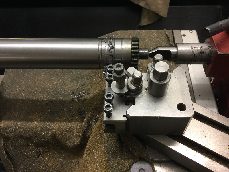 One more groove won't hurt, though this one is to be 3/16" deep. I can then use it to shape the big curve in the brass angles that will secure the roof to the front and rear spectacle plates. While I'm there, with the same set-up I turn down a 1" dia BMS bar to 0.9" dia, which is twice the radius of the desired sharp curve at the top of the cab side plates, less a few thou to allow for some springback. This will be part of the 'David and Lily' device for making the bend! I just need another two polished bars to receive the 0.9" dia one; and with one roller temporarily removed from the Formit, guess what I saw... |
|
|
|
Post by Roger on Nov 4, 2020 11:40:43 GMT
Today's job was to make a 1/16" wide (approx) groove with the mini parting tool in the removable roller of the Formit... One more groove won't hurt, though this one is to be 3/16" deep. I can then use it to shape the big curve in the brass angles that will secure the roof to the front and rear spectacle plates. While I'm there, with the same set-up I turn down a 1" dia BMS bar to 0.9" dia, which is twice the radius of the desired sharp curve at the top of the cab side plates, less a few thou to allow for some springback. This will be part of the 'David and Lily' device for making the bend! I just need another two polished bars to receive the 0.9" dia one; and with one roller temporarily removed from the Formit, guess what I saw... Hi Gary, I'm glad I'm not the only one to think that modifying machines to make job easier is perfectly reasonable and acceptable. I know some people look on in horror even at the thought of drilling an extra hole in a machine. Personally I find that bizarre, but each to their own. To my way of thinking, machine designers have a limited idea of what their machines will be used for and what might be useful. It seems strange to feel obliged to live with their short sightedness or lack of imagination when they can be improved. I've never owned a machine that I haven't modified in some form or other! Bravo! |
|
Gary L
Elder Statesman
Posts: 1,208
|
Post by Gary L on Nov 4, 2020 23:41:03 GMT
Today's job was to make a 1/16" wide (approx) groove with the mini parting tool in the removable roller of the Formit... [Snip photo] One more groove won't hurt, though this one is to be 3/16" deep. I can then use it to shape the big curve in the brass angles that will secure the roof to the front and rear spectacle plates. While I'm there, with the same set-up I turn down a 1" dia BMS bar to 0.9" dia, which is twice the radius of the desired sharp curve at the top of the cab side plates, less a few thou to allow for some springback. This will be part of the 'David and Lily' device for making the bend! I just need another two polished bars to receive the 0.9" dia one; and with one roller temporarily removed from the Formit, guess what I saw... Hi Gary, I'm glad I'm not the only one to think that modifying machines to make job easier is perfectly reasonable and acceptable. I know some people look on in horror even at the thought of drilling an extra hole in a machine. Personally I find that bizarre, but each to their own. To my way of thinking, machine designers have a limited idea of what their machines will be used for and what might be useful. It seems strange to feel obliged to live with their short sightedness or lack of imagination when they can be improved. I've never owned a machine that I haven't modified in some form or other! Bravo! Thanks Roger, though you might have set off some fireworks! I always think twice first before 'amending' a machine tool, but fundamentally they exist to do work, not to be exhibits of perfection. If there was a law against modifying them, nobody would have DROs installed (much less CNC). Then there are the unintended modifications like the scars on my milling vice. Perhaps we won't go there...  Gary |
|
Gary L
Elder Statesman
Posts: 1,208
|
Post by Gary L on Nov 5, 2020 0:26:26 GMT
Ta da!Here's the Formit again, sporting its new David and Lily Attachment!  The topmost (removable) roller is -er- removed. Nestling in between the two lower rollers is the BMS bar that I turned to the radius of the cab side/cab roof bend. One end (at right) is reduced by ⅛" in dia and grooved, to be used elsewhere to (hopefully) make the corresponding bend in the brass support angle. The M6 clamping screws I just happened to have in stock. They pass through the convenient gap provided by the bigger grooves at each end of the Formit rollers (the grooves are of course intended for bending rod or tube and even cleverer stuff). The Formit back roll is adjustable, and will need to be set up dead parallel with the front roll; the gap can be reduced to as little as about 1/16" thanks to those grooves. In my hand is another bar, threaded in a number of alternative positions, which will fit under the two rolls to receive the M6 clamping screws. It's tight, but I can just fit a cab side between the screws without fouling the sides of the Formit frame. So well done David and Lily, and thanks again for the idea! I think the David and Lily principle might solve a bigger problem that has bugging me for all the years since I started work on this loco, which is how to form the long bends in the pannier tanks. The Formit is much too small, but a single-use 3-bar lash-up might be an answer. This forum is such a great place for friendly and helpful advice and suggestions! I'm a little nervous about how close the bend in the plate is to the top of the cab door aperture. I think I shall have to dream up a way of supporting it, otherwise I could end up with a bend either side of the doorway but the middle bit unmoved; not a pretty thought! |
|
Gary L
Elder Statesman
Posts: 1,208
|
Post by Gary L on Nov 8, 2020 1:09:55 GMT
Bending the Cab SidesWith the D&L (David and Lily!) attachment installed on the Formit, it's time to do the tight curve where the cab sides meet the roof. There is no hope of bending this material by this method unless it is annealed first, but I don't want to soften and distort the rest of the plate, so once again it is on to the bricks. Placing it on a firebrick, and by shielding the lower part of the plate with another brick, it is possible to get the top edge to dull red heat, without affecting the part under the brick. It needs a LOT of heat! Placement of the shielding brick is quite critical; in the photo below, the tell-tale discolouration on the left-hand plate is a bit shy of the area to be bent, so that had to be done again to be on the safe side, with more plate protruding from the brick. Also to be on the safe side, once the area in question has reached annealing temperature and the torch turned off, I leave everything in place so that it cools down slowly and evenly, in the reverse pattern to the heating up. This shielding trick isn't infallible. If the plate is wide, the expansion of the annealed area almost guarantees a certain amount of buckling in the shielded area, but luckily the cut-out on these particular plates is such that the shielded area is never wide enough to give trouble. 
While the plates are cooling down (at least a couple of hours each!) I could start adjusting the Formit D&L attachment. It is important that the two Formit rollers are exactly parallel first (touching the little magnetic digital tilt meter across them proved the best way to check this -not shown). Then I fitted the D&L bar, and adjusted the thumbscrews to get the vertical gap even throughout its length, marking the thumbscrews with Tippex so they can be tightened up exactly in step with each other. The bend to be put into the top edge of these plates is highly critical. If the bend is a fraction too high or too low, or not straight and even, the spectacle plates won't fit, and the roofline will be 'out'. The bending is 'blind'... it is hard to see what is going on, and unlike a sharp corner, there is no mark or measurement that you can use to get it exact. The only way is to calibrate the bars to this particular job... Step 1 was to take an offcut of the brass used for the plates, (thus making sure the thickness was exactly the same). Scribe a line square across it (anywhere, it doesn't matter). Then insert the offcut under the D&L bar, and tighten the thumbscrews to a 'sweet spot' where the offcut is gripped without bending it, but all the shake is removed from the bar, so it can't wobble back and forth. Use a square to get the scribed line exactly parallel to, and perpendicularly beneath, the front edge of the D&L bar, tapping the edge gently with a soft mallet until it is spot on. 
Now start bending, tightening the thumbscrews gradually and equally ( count the turns!). With the annealed offcut, most of this could be done by hand, but with the main job, I had to apply a big adjustable spanner to get enough pressure. Eventually, (and as it gets close, by removing and checking the exact degree of bend) the offcut takes on the exact bend that will be needed in the cab plates themselves... Now the crucial bit. Fit the spectacle plate into the bend on the offcut and transfer the scribed line to the spectacle plate as accurately as possible.(Below, I'm using one of the segments of the rear Spectacle Plate- easier to work with and take photos, but of course the curve and the angle are identical. Ultimately it must be replaced by the front Spectacle Plate itself and the mark transferred to that.) 
... the line transferred to the front Spectacle Plate is to become the datum for setting up the bend; so next, one of the cab sides is aligned exactly side by side with the front Spectacle Plate and the mark transfered to that, and then extended for the whole length of the cab side with odd-leg callipers (not shown). Repeat for the other cab side. It is now possible to set up the first cab side in the apparatus in exactly the way the original bit of offcut was set up, using the scribed line and a square to get it exactly aligned with the D&L bar. Double check (by sight or by feeler gauges) that the D&L bar has exactly equal clearances at each end, and then tighten each screw exactly equally until that 'sweet spot' is reached so no wobbling of the bar away from its central position is possible. Make any final fine adjustments tapping gently with a soft mallet as before to get that scribed line exactly square. After that it is just a matter of tightening each screw equally (with the aforesaid big spanner) until the bend is complete, counting every turn. Take it very gently as the required angle gets close; better to remove the plate a few times to check than overdo it. (This is where counting the turns is so helpful, when it comes to putting the plate back in for a further tweak). The first side takes longer, but with an exact count of the turns, the second side will be a mirrored replica of the first in hardly any time at all... 
The arrow points to the narrow section above the door. Sighting this edge to the rollers gives a confirmatory check on parallelism, but there was no problem with that. I was worried that I might need to support this narrow edge (somehow) for the bending, but by sheer luck it was just wide enough to touch the bars at all times. And after removing Side 1 to offer it up to the Spectacle Plate a couple of times for checks and tweaks as the required angle gets close, at the final check it looks like this... 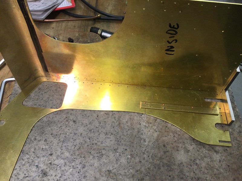
...and I am pleased with that, not to mention profoundly relieved! Happily the other end of the same plate was the same, and the second plate was an exact match. Phew! There is a waste strip about an inch wide that needs cutting off above the bend. In making the drawings, it was tempting to keep the waste, (IYSWIM) and make it the junction for the removable section of the cab roof, but I decided against that because I realised it would be impossible to match it to the ruling curve of the cab roof. (Well maybe somebofy more skilful than I could do it, but I know I couldn't.) So it will have to be trimmed back close to the start of the bend just made. But that is for another day, and must wait till the roof is rolled, so that the cut can be made at a convincing place relative to the pre-spotted rivet holes.
|
|
dscott
Elder Statesman
Posts: 2,438
|
Post by dscott on Nov 8, 2020 1:51:03 GMT
OH LOOK AT THAT!!
Yes this has made my day. And yours for thinking to use your Formit.
I have just spent 2 hours checking and amending Fowler 2 F Dock Tank drawings and transferring them to the frame metal.
Yes I have a stack of these which quietly get marked out.
Another wonderful tip is to use white sticky labels upon so you can mark out accurately. A hard sharp pencil and a cross guiding the center pop to a press. Check and a light hammer. Go over again and center punch them.
Wonderful to write notes of drill sizes by the right holes and also tapping information.
David and Lily.
|
|
barlowworks
Statesman
 Now finished my other projects, Britannia here I come
Posts: 874 
|
Post by barlowworks on Nov 8, 2020 8:51:27 GMT
Heart in mouth time Gary and it came out really well. Congratulations.
Mike
|
|
|
|
Post by Roger on Nov 8, 2020 10:21:36 GMT
Agreed, that's a superb result due to careful planning and execution of a solid idea. This is what Engineering is all about.
|
|
Gary L
Elder Statesman
Posts: 1,208
|
Post by Gary L on Nov 8, 2020 11:12:26 GMT
OH LOOK AT THAT!! Yes this has made my day. And yours for thinking to use your Formit. I have just spent 2 hours checking and amending Fowler 2 F Dock Tank drawings and transferring them to the frame metal. Yes I have a stack of these which quietly get marked out. Another wonderful tip is to use white sticky labels upon so you can mark out accurately. A hard sharp pencil and a cross guiding the center pop to a press. Check and a light hammer. Go over again and center punch them. Wonderful to write notes of drill sizes by the right holes and also tapping information. David and Lily. Thanks David and Lily I was really stuck with this until your suggestion got me thinking, so a lot of the credit is yours. I have a box of laser-printer self-adhesive white film, which was bought for a labelling project about 20 years ago. I don’t know if it is still available even, but it is totally stable and sticks well on glass or metal. It turns out to be perfect for printing out CAD drawings at full size, and you know the rest. Since then though, I’ve become a convert to laser-cutting, but I still use it for last-minute jobs. Printing CAD drawings onto card is a great way of sanity checking too, before sending them off for cutting, it worked well for the ashpan and the backhead cladding. Gary |
|
Gary L
Elder Statesman
Posts: 1,208
|
Post by Gary L on Nov 8, 2020 11:15:49 GMT
Heart in mouth time Gary and it came out really well. Congratulations. Mike Thanks Mike and Roger. I don’t think thus project would be anywhere without the support of this forum Gary |
|
don9f
Statesman
Les Warnett 9F, Martin Evans “Jinty”, a part built “Austin 7” and now a part built Springbok B1.
Posts: 960
|
Post by don9f on Nov 8, 2020 11:58:45 GMT
Yes absolutely a “Proper Job”!
Don
|
|
mbrown
Elder Statesman
Posts: 1,719
|
Post by mbrown on Nov 8, 2020 13:07:51 GMT
I shall bookmark this post as I will have a similar job to do when I get to the cab of 99 3462. Mine is smaller and will be in lighter gauge material, but similar problems with the cab door openings, windows etc loom....
You have done a superb job by approaching it as a question if precision rather than guesswork.
Nalcolm
|
|
Gary L
Elder Statesman
Posts: 1,208
|
Post by Gary L on Nov 8, 2020 17:35:38 GMT
I shall bookmark this post as I will have a similar job to do when I get to the cab of 99 3462. Mine is smaller and will be in lighter gauge material, but similar problems with the cab door openings, windows etc loom.... You have done a superb job by approaching it as a question if precision rather than guesswork. Nalcolm Hi Malcolm Very kind of you to say so, but the precision stems from the original plan to laser-cut the plates and have the rivet holes pre-spotted. It's a very precise process, and it is just as easy to draw it right as wrong (give or take a fair amount of research). Having committed to that approach, there is no way of 'making it up as you go along' or that favourite M.E. get-out of "mark out from job" except in a few, very predictable, places where there is little alternative. (i.e panels where double curvature is needed, like the bunker corners. Roger did his from solid with CNC, but most of us have to use less sophisticated methods!) The GWR tank engine cab is particularly awkward because of all the curves, but (rather to my surprise as an inexperienced plate-basher) if you take care with calculating the bend allowances a pretty high degree of precision is possible at the bends provided they are in one plane. So if it is possible, why not do it? (I believe some CAD software can even do this for you, but mine doesn't.) The GWR tank cab is also awkward (though with a certain grim fascination) because of the curious rivet spacings, As Roger has said before, they are often not symmetrical, which to a not-so-casual glance might look like a modeller's mistake. But there is always a reason, and if you discover what the reason is, it can actually help to construct the model, because braodly speaking, and give or take some thicker materials, in 7¼" gauge you mostly have to follow the full-size construction quite closely. Thus my rivets might be shifted a smidge out of their true line so that they hit the angle webs centrally, but they are otherwise correctly numbered and spaced. I don't have a problem with that; If there is any choice I would rather follow the full-size construction than be photographically exact. I was quite dismayed to realise this makes me a 'rivet counter' of sorts, but as I said, there is a certain grim fascination in getting it right, and it is just es easy to build that way as to do it wrong. There is also interest from the historic point of view. In the works photos of the prototype, it is clear that the bunker rear panels were made full width, complete with (in the case of the lower panel) a 90 degree slow bend at each end. Imagine manhandling a lump of ⅛" plate nearly 10ft long and putting an accurate bend in each end! Fascinating to think how they did that! But at least they would have had a stack of plate that size to work with. When they rebuilt 1501's bunker at the SVR they divided it into 2 halves, which would have made transport and handling a great deal easier, even if it was not strictly authentic. In engineering, there is usually a reason for everything! Gary |
|
mbrown
Elder Statesman
Posts: 1,719
|
Post by mbrown on Nov 8, 2020 18:08:10 GMT
I agree entirely. I am spending ages staring at photos of 99 3462 to work out which rivets and bolts attach which parts. This is especially interesting on the frame as many rivets and bolts hold a bracket on the outside and something else on the inside. When I was measuring her up, I noted that the brake hanger brackets inside the frames were triangular with three bolts. But I was puzzled for ages to work out where those bolts emerged outside the frame. The other night, I freeze-framed a video of her passing broadside to the camera, and managed to spot a bolt that I hadn't noticed before, hiding immediately below an external bracket. Then it dawned on me that the two lower bolts on the bracket formed a perfect triangle with the one below - and in just the right place. I also suspect that, at some date, 99 3462 was rebuilt with new plating in the cab sides, and that whoever did the job had the same problem as you - but not the wit or equipment to get it right. Look at that bit of blatant in-filling in the top corner of the cab front where it meets the curve between side sheet and roof (it is visible from outside too, so clearly the side sheet doesn't match the cab front.  DSC00477 DSC00477 by malcolm brown, on Flickr There's a prototype for everything, they say! Best wishes Malcolm |
|
Gary L
Elder Statesman
Posts: 1,208
|
Post by Gary L on Nov 9, 2020 1:10:59 GMT
I agree entirely. I am spending ages staring at photos of 99 3462 to work out which rivets and bolts attach which parts. This is especially interesting on the frame as many rivets and bolts hold a bracket on the outside and something else on the inside. When I was measuring her up, I noted that the brake hanger brackets inside the frames were triangular with three bolts. But I was puzzled for ages to work out where those bolts emerged outside the frame. The other night, I freeze-framed a video of her passing broadside to the camera, and managed to spot a bolt that I hadn't noticed before, hiding immediately below an external bracket. Then it dawned on me that the two lower bolts on the bracket formed a perfect triangle with the one below - and in just the right place. I also suspect that, at some date, 99 3462 was rebuilt with new plating in the cab sides, and that whoever did the job had the same problem as you - but not the wit or equipment to get it right. Look at that bit of blatant in-filling in the top corner of the cab front where it meets the curve between side sheet and roof (it is visible from outside too, so clearly the side sheet doesn't match the cab front. [Snip photo] There's a prototype for everything, they say! Best wishes Malcolm Well, they couldn't make that bend on a Formit, that's for sure! But there is a serious question that has no answer. If there is something on your prototype that is wrong- dubious workmanship for example, as here- do you copy it faithfully or do you put it right on your model? Everyone will have a different opinion, and all will be right. Sometimes if they had a problem in FS you get the same prob in a model for the same reason. Your photo is a classic; that could easily happen to me, and might yet !... Gary |
|
dscott
Elder Statesman
Posts: 2,438
|
Post by dscott on Nov 9, 2020 1:26:31 GMT
Yes I am also constantly looking at Photographs and this time at many of Jinty's and 2 F Dock Tanks.
Problem of course is the more you look the more the drawings are out.
It then becomes obvious that the Designer just managed to get the Works Drawings and never visited the full size Locomotives.
Such a shame when J Austen-Walton only did one design and made it one of the most difficult to build. Don't mention ASIA!!!
This is where Paddington is much easier to build than Speedy. Yes I have a full set of Drawings and everything is almost there!
On the Dock tank I now have 4 separate drawings of the frames and a view of the inside components. A further sheet has the outside components and a top view. So many drawing? Avoiding confusion and I have used them to mark out a pair. So they worked... Where they didn't I amended. These are on A 3 which is easy to handle within the workshop.
And most places can do copy's.
David and Lily.
|
|


