Gary L
Elder Statesman

Posts: 1,208
|
Post by Gary L on Nov 9, 2020 14:59:56 GMT
Yes I am also constantly looking at Photographs and this time at many of Jinty's and 2 F Dock Tanks. Problem of course is the more you look the more the drawings are out. It then becomes obvious that the Designer just managed to get the Works Drawings and never visited the full size Locomotives. Such a shame when J Austen-Walton only did one design and made it one of the most difficult to build. Don't mention ASIA!!! This is where Paddington is much easier to build than Speedy. Yes I have a full set of Drawings and everything is almost there! On the Dock tank I now have 4 separate drawings of the frames and a view of the inside components. A further sheet has the outside components and a top view. So many drawing? Avoiding confusion and I have used them to mark out a pair. So they worked... Where they didn't I amended. These are on A 3 which is easy to handle within the workshop. And most places can do copy's. David and Lily. There are two main issues with the Paddington drawings. 1. is the sheer volume of dimensional errors, or lack of any dims at all. (For anyone reading this who is struggling, I recommend Barry Leach's blog on the Cheltenham SME website. Incomplete, because sadly Barry died before he could finish his Paddington, but a good starting point.) Issue 2 is more subtle. It is clear to me that, as you say in your first paragraph, David Adams was working from a copy of the Swindon GA, but nothing else. Thus, where items could be scaled from the GA, they are generally reasonably accurate, but where they are not detailed or not shown at all on the GA (like the backhead, the dampers and numerous smaller details) he was forced to improvise, and sometimes omit. I do not criticise him for this; back in the day the detail drawings existed of course, but they were not catalogued or curated so he had to make do without. I suspect just obtaining the GA alone would have been a minor triumph. Even now, it would be difficult to interpret some of the drawings without the extensive library of detail photos that enthusiasts like Roger and others have made available on the web. We also have to contend with technological advances. Substantial parts of LBSC's oeuvre are now considered unacceptable by modern standards. This means that drawings that were intended for a basic or beginner's level of skill, can nowadays only be safely undertaken by somebody with fairly advanced knowledge, and that kind of person (Roger again!) will quickly find them crude and unsatisfactory. The technology in Paddington is mainstream (and safe!) but scarcely adventurous. If you want to incorporate O-rings, plastics, adhesives, lost-wax detailing and so on, you must work it out yourself. That is not a criticism, just an observation. There are not that many modern high-quality drawing sets available as far as I can see. Gary |
|
Gary L
Elder Statesman
Posts: 1,208
|
Post by Gary L on Nov 9, 2020 20:15:09 GMT
With the cab sides adequately bent, the waste needs to be trimmed off, and done very tidily because this particular seam will stick out like a sore thumb if it is in any way ragged. Not so very easy to achieve. It's a long cut with a hacksaw, but worse, very hard to support while sawing. I don't have a bandsaw, and a jigsaw cut would need a great deal of careful trimming with a file afterwards, and the same issue with workholding. A slitting saw is my preferred method, but it's very hard to set up a cut square to the bent surface, and there is not a lot of room under the throat of the mill. After a lot of head-scratching, I clamped a nice square piece of softwood (offcut from a pruned bunk-bed) into the tilting drill-vice and turned it wrong-way round. (It has to be back to front, because otherwise the work can't reach the saw) and I could just (only just) get the vice handle to pass under the mill. A bit of masking tape had to pressed into service to stop the bar of the handle dropping... 
It's not as rigid as I would like, but a thin slitting saw doesn't impose a great deal of pressure. Check the saw against the scribed line several times and once for luck to make sure the cutting line is exactly horizontal and away we go. As with many things, setting up (including thinking) took hours, doing the cut took just a few minutes. "Check & Repeat" on the other side... -------------------- With that done, and fresh from a successful expedition with the Formit, I hoped to put the corresponding bends into the brass angle that makes the corner between the Spectacle Plate(s), these cab sides, and the roof. Is it always the 'trivial' jobs that cause most pain?... I was expecting rolling the easy curve in the ¼" x ¼" x 1/16" angle for the roof to be straightforward and easy after the last job. Not a bit of it! I assumed first that I wouldn't need to anneal the angle, since the curve was quite easy. Not really. It was not only springy and hard work, but despite the special groove I'd cut in the roller, the angle wanted to curve in all directions. So I tried to anneal it. I took it up to red heat and let it cool, but it was still pretty stiff and springy, only this time it had acquired an extra curl (in the wrong direction needless to say) from the heating. Put it into the Formit and try again. Another mistake. I should have eased off the setting screws (a lot), so instead of springing back like it did first time, it had softened enough to 'take' the bend more effectively... so this time I had made a much sharper bend than I wanted. I tried to undo the mess (sorry no humiliating photos) without much success, and by then I had pretty much wrecked this particular length of angle. Had I got it hot enough for annealing? I tried again, only this time it suddenly broke in the middle without warning. Obviously it went past the melting point in that spot. OK, not the end of the world, but this material is not the pushover I was expecting... 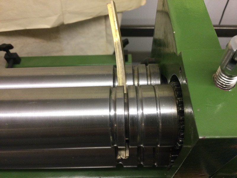
So here's the broken-off bit, back in the Formit, for a bit of experimentation and practice. You can't see the intended curve in the picture because of the angle of the camera, but you can see the unwanted curve, and the distinct twist. An angle was never going to be easy to bend (that's the point of an angle after all!) but if it needs extensive handwork to correct all this unwanted snaking, it defeats the object of rolling it in the first place. And this extruded brass is not the same material as the nice predictable brass sheet I've been dealing with so far. So I'm a bit stumped now. Has anybody got any suggestions please? |
|
|
|
Post by andyhigham on Nov 9, 2020 20:30:52 GMT
Thinking outside the box.
Most things on a loco are in pairs, opposite handed.
How about soldering two lengths of annealed angle back to back into a T section, then roll the curve and finally de solder them
|
|
|
|
Post by Roger on Nov 9, 2020 20:33:56 GMT
Hi Gary,
Did you anneal it first? If not, I think that would help. You can also anneal it after it's been bent so it can be straightened more easily.
Where does this piece go? The only place I can think of is the inside of the bottom of the bunker rear corners. If so, it's not going to be seen. Personally, I think this will straighten out easily once it's annealed.
|
|
|
|
Post by gwr14xx on Nov 9, 2020 20:47:18 GMT
"Has anybody got any suggestions please?"
Hi Gary, Try cutting male and female formers out of ¼" thick bright steel. Then, having annealed the brass, pull it round the male former, clamp it lightly in place with the female former, then using another piece of bright steel flat, sandwich it between the formers and the flat, and give it a squeeze in the vice to straighten everything up. Regards, Eddie. |
|
mbrown
Elder Statesman
Posts: 1,720
|
Post by mbrown on Nov 9, 2020 21:06:45 GMT
I have never had much luck with bending extruded brass angle... I turned grooves in my home-made rollers hoping it would work, but I always get twists in both directions. To overcome this, I have either made the part out of two pieces of sheet silver soldered together, or (if only the outer edge is visible) cut notches out of the horizontal edge, bent the piece around, adjusting the notches if necessary to let it take the right shape, and then silver soldered up the remaining spaces where the notches were. Neither is especially neat or easy...
M Machine Metals catalogue shows extruded brass angle as CZ121 - and ordinary brass sheet as CZ120. I am not sure of the difference in composition, but in terms of handling that one digit difference makes a lot of trouble.
Malcolm
|
|
millman
Part of the e-furniture

Posts: 297 
|
Post by millman on Nov 9, 2020 22:04:58 GMT
I have been trying to roll some 3/8 by 1/16 thick angle this week, I need it rolled to a 12 inch radius, I have annealed it but no matter what I do I get a twist that I cannot get rid of. I have wasted a couple of three foot lengths trying different methods and have now given up on the rolling.
|
|
|
|
Post by Roger on Nov 9, 2020 22:59:18 GMT
Thinking outside the box. Most things on a loco are in pairs, opposite handed. How about soldering two lengths of annealed angle back to back into a T section, then roll the curve and finally de solder them I think this is probably the simplest way to achieve the desired bend without twisting. |
|
Gary L
Elder Statesman
Posts: 1,208
|
Post by Gary L on Nov 9, 2020 23:40:04 GMT
Hi Gary, Did you anneal it first? If not, I think that would help. You can also anneal it after it's been bent so it can be straightened more easily. Where does this piece go? The only place I can think of is the inside of the bottom of the bunker rear corners. If so, it's not going to be seen. Personally, I think this will straighten out easily once it's annealed. I didn’t anneal it for the first attempt. The radius is only some 11.75”, so I thought I might get a smoother curve without. I was wrong! It goes under the roof to hold it on, so not very visible, but I’d like to get it right (as we all like to). WRT annealing, I was quite surprised, (dismayed might be a better word) at how unyielding it remained. It was still unworkable unless clamped in a vice and remained pretty springy, hence my doubts about whether I had got it hot enough to anneal at all, and so to the second attempt. That didn’t end well! Gary |
|
|
|
Post by Roger on Nov 9, 2020 23:59:19 GMT
Hi Gary, Did you anneal it first? If not, I think that would help. You can also anneal it after it's been bent so it can be straightened more easily. Where does this piece go? The only place I can think of is the inside of the bottom of the bunker rear corners. If so, it's not going to be seen. Personally, I think this will straighten out easily once it's annealed. I didn’t anneal it for the first attempt. The radius is only some 11.75”, so I thought I might get a smoother curve without. I was wrong! It goes under the roof to hold it on, so not very visible, but I’d like to get it right (as we all like to). WRT annealing, I was quite surprised, (dismayed might be a better word) at how unyielding it remained. It was still unworkable unless clamped in a vice and remained pretty springy, hence my doubts about whether I had got it hot enough to anneal at all, and so to the second attempt. That didn’t end well! Gary Ah, I see where that is. I cheated and machined the angle from solid. I suppose the issue is that it's not being rigidly supported from side to side when it's being rolled. That's how it's done on industrial machines and they do it easily. I think Andy has the best idea, soldering two pieces together. You're going to need the same on the rear of the bunker anyway, so you can kill two birds with one stone. |
|
Gary L
Elder Statesman
Posts: 1,208
|
Post by Gary L on Nov 10, 2020 0:12:14 GMT
"Has anybody got any suggestions please?"
Hi Gary, Try cutting male and female formers out of ¼" thick bright steel. Then, having annealed the brass, pull it round the male former, clamp it lightly in place with the female former, then using another piece of bright steel flat, sandwich it between the formers and the flat, and give it a squeeze in the vice to straighten everything up. Regards, Eddie. Hi Eddie Thanks for the suggestion, and it might work in a smaller loco, but bear in mind this bend is about a foot long and a foot radius, so a pair of former plates would be a seriously heavy bit of work, and hand work at that, although I suppose laser cutting would be a possibility. No, I think it's got to be rollers of some description, the same as they would do it in full-size, but I must be doing something horribly wrong! Gary |
|
Gary L
Elder Statesman
Posts: 1,208
|
Post by Gary L on Nov 10, 2020 0:32:24 GMT
Thinking outside the box. Most things on a loco are in pairs, opposite handed. How about soldering two lengths of annealed angle back to back into a T section, then roll the curve and finally de solder them I think this is probably the simplest way to achieve the desired bend without twisting. Millman and Malcolm -tell me about it!  Glad I'm not alone... Andy Now that really is lateral thinking! I give you the prize for best suggestion thus far! It will need another, wider, groove in the long-suffering Formit. My anxiety is, having done that, would the bending would lock up stress in the two angles, so they would submit relatively placidly to the bending while the stresses cancel each other out, but then spring apart when unsoldered at the end? But it sounds worth a try for science's sake, and it's not the end of the world if it doesn't work. Many thanks to all who have replied so quickly- it is so helpful to chew these things over Gary |
|
Gary L
Elder Statesman
Posts: 1,208
|
Post by Gary L on Nov 10, 2020 1:16:27 GMT
I didn’t anneal it for the first attempt. The radius is only some 11.75”, so I thought I might get a smoother curve without. I was wrong! It goes under the roof to hold it on, so not very visible, but I’d like to get it right (as we all like to). WRT annealing, I was quite surprised, (dismayed might be a better word) at how unyielding it remained. It was still unworkable unless clamped in a vice and remained pretty springy, hence my doubts about whether I had got it hot enough to anneal at all, and so to the second attempt. That didn’t end well! Gary Ah, I see where that is. I cheated and machined the angle from solid. I suppose the issue is that it's not being rigidly supported from side to side when it's being rolled. That's how it's done on industrial machines and they do it easily. I think Andy has the best idea, soldering two pieces together. You're going to need the same on the rear of the bunker anyway, so you can kill two birds with one stone. Hi Roger I don't know about cheating, but sometimes I visualise you surrounded by piles of the swarf you've made during your Speedy project, unable to find a way out!  I've never seen an industrial machine doing this, but that would be the principle to adopt I'm sure, if it could be miniaturised- copy the people who've made it work! I think the problem is made worse because I am bending in the least favourable direction; trying to stretch the base of the angle, which resists and tries to cut the corner, while compressing the peak (which requires the slot in the roller to be wider, which means less support in the early stages of the bend). Because of the 'corner cutting' I think a successful machine might need an extra pair of wheels at right angles to the desired curve to induce an opposite bend to counteract the twist. It's a tall order, just for this pair of bends... So I'll give Andy's suggestion a whirl. At worst if I mess up some more brass angle, it isn't as serious as messing up a laser-cut plate! And I like the elegance of the idea. A bit of experimentation has proved that trying to press the tight radii at either end of the main roof curve was never going to work. I will cut out the web altogether in those places, then that bit at least will be easy. Not authentic, but just about credible, and very hard to see anyway. It could be done by forging if I was using steel, but that's impossible in brass. Gary |
|
dscott
Elder Statesman
Posts: 2,438
|
Post by dscott on Nov 10, 2020 1:39:03 GMT
 Just pondering many things at the moment and turning a 6 1/4" diameter new ring to fit the boiler to my Hunslet. Yes another difficulty piece to machine without CNC equipment. The question is of having turned the ring or rings to the best curve. Is it now easier to go more on part of the bend or do a smaller ring within the middle. Thoughts turn to outward sticking T sections for the rear of the bunker. and of course the Radial T section for the cab openings. Steel or brass. And add a bit more to the bottom of the T as when bent it reduces in height. David and Lily. |
|
|
|
Post by Roger on Nov 10, 2020 9:26:57 GMT
Ah, I see where that is. I cheated and machined the angle from solid. I suppose the issue is that it's not being rigidly supported from side to side when it's being rolled. That's how it's done on industrial machines and they do it easily. I think Andy has the best idea, soldering two pieces together. You're going to need the same on the rear of the bunker anyway, so you can kill two birds with one stone. Hi Roger I don't know about cheating, but sometimes I visualise you surrounded by piles of the swarf you've made during your Speedy project, unable to find a way out! I've never seen an industrial machine doing this, but that would be the principle to adopt I'm sure, if it could be miniaturised- copy the people who've made it work! I think the problem is made worse because I am bending in the least favourable direction; trying to stretch the base of the angle, which resists and tries to cut the corner, while compressing the peak (which requires the slot in the roller to be wider, which means less support in the early stages of the bend). Because of the 'corner cutting' I think a successful machine might need an extra pair of wheels at right angles to the desired curve to induce an opposite bend to counteract the twist. It's a tall order, just for this pair of bends... So I'll give Andy's suggestion a whirl. At worst if I mess up some more brass angle, it isn't as serious as messing up a laser-cut plate! And I like the elegance of the idea. A bit of experimentation has proved that trying to press the tight radii at either end of the main roof curve was never going to work. I will cut out the web altogether in those places, then that bit at least will be easy. Not authentic, but just about credible, and very hard to see anyway. It could be done by forging if I was using steel, but that's impossible in brass. Gary Hi Gary, Your vision of the swarf would certainly be true if I put all of the swarf in one place. The industrial machines are on YouTube if you search for 'bending angle iron'. You may be right about the stress in the angles if bent as a pair, but my guess is that it won't be a problem. You will have forced the angles to bend where they're supposed to. You're not bending them in the wrong plane, so there shouldn't be any spring back. The tight bend could be machined from a round Brass bar bar end. |
|
|
|
Post by andyhigham on Nov 10, 2020 10:04:23 GMT
Another thought.
The rollers on the "flat" side of the angle could have flat bottomed grooves the width of the angle, the roller on the "leg" side of the angle a groove the width of the leg (plus a bit) but not quite the depth of the leg.
This would put the bending pressure on the top of the leg compressing the edge rather than trying to stretch the flat side. The grooves in the flat side should hold it in line and if the rollers were adjustable axially could be used to dial out any twist
|
|
|
|
Post by andyhigham on Nov 10, 2020 10:06:50 GMT
|
|
Gary L
Elder Statesman
Posts: 1,208
|
Post by Gary L on Nov 10, 2020 11:03:18 GMT
Hi Andy That looks like a handy device. I was thinking rail bender, but it doesn't quite measure up to the bar section we are using on our new 7¼" track. It's a good price for anybody who has a lot of bending to do, and it looks well-made. Hopefully these roof angle bends are my last! Regarding the groove(s) in the Formit, I'm going to try your plan A first, and widen the groove to accommodate a double thickness. I was not sure how deep the groove for the vertical leg needed to be, so at first I was quite conservative and matched it to the leg or a little less, as you suggest in fact. However (for the benefit of those who might come after) I found it aggravated matters by swelling the top of the vertical leg, which caused it to jam in the groove. I therefore deepened the groove and widened it by a few thou. I think it would have been better to have just deepened it, because widening it reduces the guidance in then vertical plane. I'n now going to widen the goove anyway, so I can pay more attention to the exact clearance needed. Gary |
|
Gary L
Elder Statesman
Posts: 1,208
|
Post by Gary L on Nov 10, 2020 11:23:11 GMT
Hi Roger I don't know about cheating, but sometimes I visualise you surrounded by piles of the swarf you've made during your Speedy project, unable to find a way out! I've never seen an industrial machine doing this, but that would be the principle to adopt I'm sure, if it could be miniaturised- copy the people who've made it work! I think the problem is made worse because I am bending in the least favourable direction; trying to stretch the base of the angle, which resists and tries to cut the corner, while compressing the peak (which requires the slot in the roller to be wider, which means less support in the early stages of the bend). Because of the 'corner cutting' I think a successful machine might need an extra pair of wheels at right angles to the desired curve to induce an opposite bend to counteract the twist. It's a tall order, just for this pair of bends... So I'll give Andy's suggestion a whirl. At worst if I mess up some more brass angle, it isn't as serious as messing up a laser-cut plate! And I like the elegance of the idea. A bit of experimentation has proved that trying to press the tight radii at either end of the main roof curve was never going to work. I will cut out the web altogether in those places, then that bit at least will be easy. Not authentic, but just about credible, and very hard to see anyway. It could be done by forging if I was using steel, but that's impossible in brass. Gary Hi Gary, Your vision of the swarf would certainly be true if I put all of the swarf in one place. The industrial machines are on YouTube if you search for 'bending angle iron'. You may be right about the stress in the angles if bent as a pair, but my guess is that it won't be a problem. You will have forced the angles to bend where they're supposed to. You're not bending them in the wrong plane, so there shouldn't be any spring back. The tight bend could be machined from a round Brass bar bar end. Ah yes. This video www.youtube.com/watch?v=F_cVs1DWfQs shows how much 'art' is involved, even for a professional with a very expensive-looking machine. (They call it a 'leg-in bend') Note the extra 4th and 5th rollers with hydraulic adjustment in-out and up-down. Not much hope of adapting the Formit! -Gary |
|
nonort
Part of the e-furniture
If all the worlds a Stage someone's nicked the Horses
Posts: 277
|
Post by nonort on Nov 10, 2020 12:04:41 GMT
A bit further outside the box why not use mild steel, much less brittle or even stainless if its to be under water?
Just my penny worth.
|
|


 Glad I'm not alone...