|
|
Post by andyhigham on Nov 10, 2020 19:43:24 GMT
|
|
Gary L
Elder Statesman

Posts: 1,208
|
Post by Gary L on Nov 11, 2020 0:18:25 GMT
A bit further outside the box why not use mild steel, much less brittle or even stainless if its to be under water? Just my penny worth. Hi Nonort The flip answer is it would spoil the advantages of using brass for the rest of the plate work. But there's a technical reason too; I am spotting the rivet holes through pre-cut holes in the brass plates. With a harder material to drill into, I'm sure the drill would wander. Some of the holes will have to be pistol-drilled in-situ, so again a hard material would make life difficult. As for stainless, with a pistol-drill in-situ AAARRRGH no! But thanks for contributing. It's the only way I'm learning how to do some of this stuff! Gary |
|
Gary L
Elder Statesman
Posts: 1,208
|
Post by Gary L on Nov 11, 2020 1:57:09 GMT
I know you are all agog to know how the Andy Higham suggestion worked out WRT bending the roof curve in the brass angle, and the answer is... pretty well!! Annealing was the first step, and even with the benefit of yesterday's experience, this stuff is not easy. I managed not to melt it, but it gets very soft around annealing temperature, just as it starts to visibly glow; distinctly floppy in fact. If it were more controllable, this might be the answer to the bending dilemma, but I don't fancy it. Anyway I only annealed the distance I needed to bend plus an inch or two for luck, and when it cooled down it was almost exactly not as straight as it was before... so that needed half an hour of vice and pliers work to try and persuade it back onto the straight and narrow. Next a clean-up with emery and a smear of solder paint, clamp the two angles back-to-back with toolmakers clamps (am I the only one who abuses these things so badly?) and waft the torch along it (or rather, them). I only soldered the portion I wanted to bend. I should have soldered at least an inch or two into the straight section as well, because after the first pass through the rollers the unsoldered portion started to splay apart...  ... but I didn't think this was serious, so I squeezed them back together and held them that way with a toolmaker's clamp to teach them some manners. Here's an early stage view of passing them through the mangle. You'll see that I have widened the groove to suit the doubled thickness. The groove is about 5 thou wider than the stock at its widest point (there was about 8 thou variability due to the residual annealing wiggle, and the soldering.) The groove is about 5 thou deeper than what from the videos I now gather is properly called the 'leg' of the angle. This seems to give better results than allowing it to 'bottom' in the groove.  The key thing to notice is they are coming out flat, so it's looking hopeful... I was able to match the curve of the roof this way, without any obvious curling out of plane, but the next step was to make the sharp bend where the roof meets the cab sides. As I mentioned before, I had abandoned any flimsy hope of bending or pressing the solid angle round such a small radius. But I wanted to keep the strip in one piece if possible, so here is what I did:  It involves cutting away part of the leg where the bend is to be, with a piercing saw and a knife-shaped needle file. Not the easiest job, and it is supposed to be 2x ⅜" radii. It's a bit approximate, and this is a bit experimental; if it didn't come off, I could easily cut away the 'leg' there entirely, for the short distance required. So then I went back to the Formit. If you look back a page or so, you'll see that I had put a short extension on the RH end of my "David and Lily" attachment for pressing this bend. Well, the D&L needed the slot widening of course, just like the main roller, but this time it was only going to have to bend the flat, not the leg. And by sheerest beginners' luck it came out like this...  No, me neither! I was a bit surprised when it came out of the Formit, because this wasn't exactly what I'd planned, and remember this is all done totally blind; I had no idea what was going on, other than the increasing bending. If anybody wants to copy this lucky strike, bear in mind that I think the bend ended up shifted a little way along the strip; but it didn't matter a bit, because I had an excess amount of roof bend available, and the material was straight on the other side of this bend, as intended. Now I could, and I possibly should, solder up the gaps, but I probably won't, because the angle is plenty strong enough; the paint will fill the gaps, and it will be out of line-of-sight anyway. So I now had the angle bent pretty exactly to the profile of the spectacle plate, and with no serious curling even if it wasn't quite perfectly flat. Better still, I had two of them, exactly matched and symmetrical, for no extra work. The acid test of Andy's idea would come when the two angles were unsoldered. This was heart-in-mouth time with a vengeance... And here is the result:  As you can see, it is reasonably flat in the important plane, but there is a degree of twist. So still clamped in the vice, grab the twisted end with a mini-sized adjustable spanner and tweak it the other way. Well it needed a pretty muscular tweak, because as noted, even when annealed this extruded brass is not what anyone would call soft and pliable; but even so it was successful. The resultant profile was not completely flat, but a few moments of bashing it with the dead-blow hammer on the granite block and it was fine. In fact it was more than fine. The twisting and bashing had not materially altered the curvature, and except in a couple of spots that can be easily corrected with a file, the angle remained at 90 degrees throughout. So it was clamp it to the Spectacle Plate as accurately as possible and drill through all the rivet holes and we end up with this (not quite finished)...  ...which is much better than I dared hope, and entirely due to Andy's "thinking outside the box"! So many thanks for that Andy! This is obviously the go-to method as far as I am concerned now. You will realise that the angle is in two not-quite-symmetrical parts. (I didn't want to join it on the exact centreline, because there is a hole to go there for the whistle shield support.) I now have to a similar thing for the rear Spec Plate, but because of the removable section in the roof, this falls more naturally into three parts, not two, so there isn't a 'pair' for the angle. Never mind, lesson learned. The way to do it is the same 'doubling' method, but using a 'sacrificial' length of angle, which will be discarded. It might seem wasteful, but it hardly matters if it guarantees a reliable result using Andy's method. But that's for tomorrow! |
|
|
|
Post by Deleted on Nov 11, 2020 8:30:01 GMT
That looks superb Gary...great work sir.
Pete
|
|
|
|
Post by andyhigham on Nov 11, 2020 8:54:59 GMT
I'm really glad that worked. Now we have a "go to" method to put in the memory bank
|
|
|
|
Post by Roger on Nov 11, 2020 9:17:48 GMT
Full marks to Andy for the idea, and Gary for proving its worth! A very useful approach to remember for the future.
|
|
kipford
Statesman
 Building a Don Young 5" Gauge Aspinall Class 27
Posts: 566 
|
Post by kipford on Nov 11, 2020 10:53:47 GMT
Gary How about slot and tab laser cut parts soldered together. Can be done in either steel or brass. Bonus is you can put any rivet holes in at the same time to be used for spotting through. I did my cab side beading this way (MEL did the parts for me). If do not have the CAD software to do it, pm me and I can easily create the developed parts for you. Dave  Cab Bead2 Cab Bead2 by Dave Smith, on Flickr 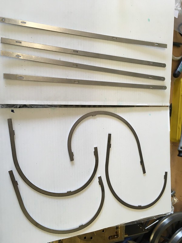 IMG_2197 IMG_2197 by Dave Smith, on Flickr  IMG_2198 IMG_2198 by Dave Smith, on Flickr  IMG_2200 IMG_2200 by Dave Smith, on Flickr |
|
Gary L
Elder Statesman
Posts: 1,208
|
Post by Gary L on Nov 11, 2020 11:47:26 GMT
Gary How about slot and tab laser cut parts soldered together. Can be done in either steel or brass. Bonus is you can put any rivet holes in at the same time to be used for spotting through. I did my cab side beading this way (MEL did the parts for me). If do not have the CAD software to do it, pm me and I can easily create the developed parts for you. Dave Cab Bead2 by Dave Smith, on Flickr [Some pix snipped] Hi Dave I hadn't given much thought to the cabside beading, but it is time I did! I can see your method offers distinct possibilities. When you say 'soldered together' did you silver-solder them or soft solder? I'm not keen to reproduce the myriad small rivets that the prototype uses to secure the beading to the cab side; it's a level of detail too far for me, and it will be difficult enough to paint this area without having to contend with rivets as well. However I can see that a judicious number of countersunk rivets will be helpful to give a mechanical attachment ahead of (probably) soft-soldering it for a final bond. That would tend to indicate silver-solder to assemble the Tee section itself, is that what you did? It's quite delicate work. I wouldn't have entertained doing it this way when I first did the cab drawings, but since then I've been pleasantly surprised (read 'amazed') at how accurately bend allowances can work out. Well, not in respect of professionals of course, but in terms of what a humble inexperienced metal butcher like myself can achieve with the aid of CAD and laser-cutting. Gary |
|
|
|
Post by Roger on Nov 11, 2020 12:03:04 GMT
Hi Gary,
The beading is the same as on the bunker, just bent the other way. I made all of it flat and then bent it with my pipe bender. Being that shape it doesn't twist like the angle did.
Prsonally I'd machine a length of 'T' section and file the rounded top and then bend it. I used tiny rivets to hold it in place and then filed them off because they were so small.
|
|
kipford
Statesman
Building a Don Young 5" Gauge Aspinall Class 27
Posts: 566
|
Post by kipford on Nov 11, 2020 13:38:54 GMT
Gary
I silver soldered it, but no reason why it could be soft soldered.
Dave
|
|
|
|
Post by coniston on Nov 11, 2020 21:55:20 GMT
Excellent work Gary, thanks for proving Andy's idea, one for the memory bank.
Chris D
|
|
Gary L
Elder Statesman
Posts: 1,208
|
Post by Gary L on Nov 11, 2020 23:53:45 GMT
Gary I silver soldered it, but no reason why it could be soft soldered. Dave That makes sense. How did you fix it to the cab Dave? Gary |
|
Gary L
Elder Statesman
Posts: 1,208
|
Post by Gary L on Nov 12, 2020 1:17:38 GMT
Hi Gary, The beading is the same as on the bunker, just bent the other way. I made all of it flat and then bent it with my pipe bender. Being that shape it doesn't twist like the angle did. Prsonally I'd machine a length of 'T' section and file the rounded top and then bend it. I used tiny rivets to hold it in place and then filed them off because they were so small. It's a difficult choice, and one I had hoped to put off, but progress has been faster than I expected so I can't leave it a lot longer. Milling has the advantage of being available immediately, but another special arrangement would be needed for rolling it. It would be a very unequal-limbed Tee, so it might be just as troublesome to bend as angle but without recourse to the Andy H method. And the question of fixing it in place is relevant. If I use (concealed) rivets then the stem of the Tee will need to be similar in height to width of the beading, which means a lot of handle-twirly on the mill and makes the bending issue more severe. A decent upstand is desirable if sold-solder alone is used too, perhaps more so. If I go Dave Kipford's route, which is very tempting, I need to get on with it very soon, because of the inevitable production time lag. Hmmm... Gary |
|
dscott
Elder Statesman
Posts: 2,438
|
Post by dscott on Nov 12, 2020 1:31:40 GMT
 Here is one I took last year of a broadside of the cab side... Yes the tiny rivets driving someone mad. Now in O Gauge they have something called a riveting tool which in our scales could possibly press something resembling a large O Gauge rivet. The brass being pushed out into a tiny form and No Drills being harmed. A possibility of 3 or 4 of them to hold the beading in place. David and Lily. |
|
barlowworks
Statesman
Now finished my other projects, Britannia here I come
Posts: 874
|
Post by barlowworks on Nov 12, 2020 8:06:13 GMT
Hi Gary, David and Lily. If you look on page three of my thread "It started with a buffer" about 2/3 down you will see the drop weight riveting tool I use in o gauge. While it will form beautiful rivets in thin sheet I have found that for thicker stuff you may have to part drill the rivet holes half way through to form a good rivet.
Mike
|
|
|
|
Post by Roger on Nov 12, 2020 9:59:55 GMT
Hi Gary, The beading is the same as on the bunker, just bent the other way. I made all of it flat and then bent it with my pipe bender. Being that shape it doesn't twist like the angle did. Prsonally I'd machine a length of 'T' section and file the rounded top and then bend it. I used tiny rivets to hold it in place and then filed them off because they were so small. It's a difficult choice, and one I had hoped to put off, but progress has been faster than I expected so I can't leave it a lot longer. Milling has the advantage of being available immediately, but another special arrangement would be needed for rolling it. It would be a very unequal-limbed Tee, so it might be just as troublesome to bend as angle but without recourse to the Andy H method. And the question of fixing it in place is relevant. If I use (concealed) rivets then the stem of the Tee will need to be similar in height to width of the beading, which means a lot of handle-twirly on the mill and makes the bending issue more severe. A decent upstand is desirable if sold-solder alone is used too, perhaps more so. If I go Dave Kipford's route, which is very tempting, I need to get on with it very soon, because of the inevitable production time lag. Hmmm... Gary Have you looked at the works drawing of the 'T' section? I'm not sure what you mean by 'very unequal-limbed Tee'. It formed easily enough in the pipe bender with the aid of a couple of shaped rollers. |
|
|
|
Post by Roger on Nov 12, 2020 10:02:13 GMT
Here is one I took last year of a broadside of the cab side... Yes the tiny rivets driving someone mad. Now in O Gauge they have something called a riveting tool which in our scales could possibly press something resembling a large O Gauge rivet. The brass being pushed out into a tiny form and No Drills being harmed. A possibility of 3 or 4 of them to hold the beading in place. David and Lily. It's worth having a really close look at the different rivet sizes on this picture. Another thought... if you made a model with all those imperfections, it would be considered to be a very rough build! |
|
|
|
Post by Deleted on Nov 12, 2020 11:52:47 GMT
Here is one I took last year of a broadside of the cab side... Yes the tiny rivets driving someone mad. Now in O Gauge they have something called a riveting tool which in our scales could possibly press something resembling a large O Gauge rivet. The brass being pushed out into a tiny form and No Drills being harmed. A possibility of 3 or 4 of them to hold the beading in place. David and Lily. It's worth having a really close look at the different rivet sizes on this picture. Another thought... if you made a model with all those imperfections, it would be considered to be a very rough build! In my mind's eye, there's a fine line to be trodden between making a model too good and making it look too rough, I am talking the final finish here rather than the model engineering involved. To good and it looks like a toy, too rough and it looks a mess. Having said that our club treasurer who is building a lovely 3 1/2 loco, alas I forget what it is but it's 3 cylinder with Gresley conjugated valve gear so perhaps a V2 or V4. For him, all dents/marks have to be included in his build. I recall him bringing in part of the boiler cladding he had just done at one of the 'work in progress' evening's where he showed pictures of the prototype and how he had replicated the various dents in the cladding. Now there's a man on a mission...  Pete |
|
kipford
Statesman
Building a Don Young 5" Gauge Aspinall Class 27
Posts: 566
|
Post by kipford on Nov 12, 2020 12:39:04 GMT
Gary
Not fixed the beading on yet, but the intension is to soft solder them.
Dave
|
|
Gary L
Elder Statesman
Posts: 1,208
|
Post by Gary L on Nov 12, 2020 14:59:19 GMT
It's a difficult choice, and one I had hoped to put off, but progress has been faster than I expected so I can't leave it a lot longer. Milling has the advantage of being available immediately, but another special arrangement would be needed for rolling it. It would be a very unequal-limbed Tee, so it might be just as troublesome to bend as angle but without recourse to the Andy H method. And the question of fixing it in place is relevant. If I use (concealed) rivets then the stem of the Tee will need to be similar in height to width of the beading, which means a lot of handle-twirly on the mill and makes the bending issue more severe. A decent upstand is desirable if sold-solder alone is used too, perhaps more so. If I go Dave Kipford's route, which is very tempting, I need to get on with it very soon, because of the inevitable production time lag. Hmmm... Gary Have you looked at the works drawing of the 'T' section? I'm not sure what you mean by 'very unequal-limbed Tee'. It formed easily enough in the pipe bender with the aid of a couple of shaped rollers. Oh yes Roger, very much so, it's on p4 of this thread! Here's a reminder... You'll see that it is already assymetric in the prototype, but in the model we have to accommodate the extra thickness of the cab sides, which pushes the 'leg' or the stem of the Tee further off to one side. I think the full-size platework was made of ⅛" plate or thereabouts, whereas 1.5mm brass scales at just under half an inch! So that means the original 1⅛" dimension in the drawing (scale 9/64" or 3.57mm) needs to be increased to a smidge under 3/16" or 4.76mm without increasing the width of the beading which is 2⅛" (scale 17/64" or 6.75mm). If the stem of the Tee is also made a little thicker than scale (which would otherwise be less than 1/32" or around 0.6mm, then the 'interior' limb of the horizontal portion of the Tee can only be around 1mm wide. Here is the GWR dwg again (it is the one on the right we need): And here is David Adams's interpretation, which is way overscale, but shows the eventual proportions we need quite well (this time it's the lower one we are interested in): 
So that's why I'm not yet convinced about milling it from solid. Bending it will be not much different from bending plain angle, with all the nastinesses that involves, and with little scope for using the Andy H method. I suppose I could solder a 2mm or so spacer in-between two sections, so its not out of the question, but it will be tricky, and the eventual section to be bent would be roughly twice as heavy as before and with a much tighter curve to be rolled. It would however be in the 'favourable' direction ('leg out') so it's not all bad.
Still thinking about it!
Gary |
|