Part 9 - 2 to 1 levers and slide valves
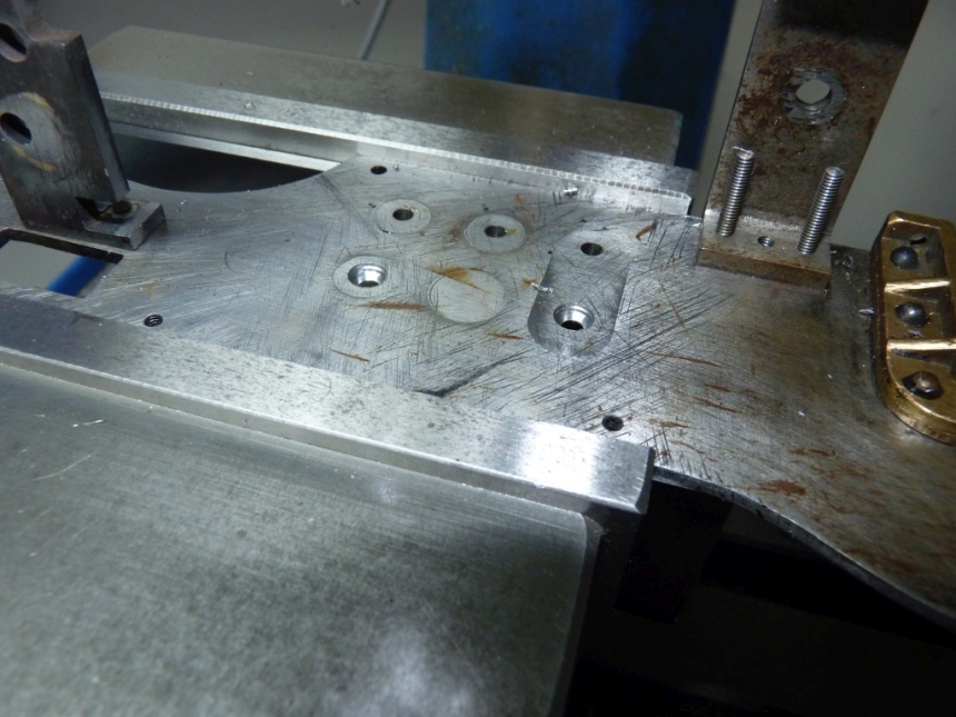
Before moving onto the 2 to 1 levers there was one job on the frames that needed doing. That was to countersink the top two mounting holes for the outside cylinders so that countersink head screws could be used. Normal hex head bolts or studs and nuts can't be used because they would get in the way of the inside cylinder.
The countersink screws that I buy always seem to have a small flat section on the head before the countersink bit starts. If you use an ordinary countersink bit then by the time you have made the countersink deep enough to allow the screw head to lie flush with the surface the countersink in the frame is much larger in diameter than the head which looks bad. Ideally you want a countersink bit the same diameter as the screw head but they usually aren't.
I tend to cheat and drill a shallow hole with an ordinary drill the same size as the screw head, just deep enough to allow the head to sit flush and then finish the hole with a 90 °spot drill or similar.
What I really need is a set of drills with the ends ground to 90° rather than 118° or at least a few drills to match the screw sizes that I use. What do other people use?

Onto the 2 to 1 lever assembly.
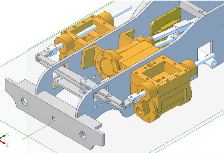
The purpose of the levers is to combine the motion of both sides of the outside valve gear and provide the correct motion for the inside valve without having to use a separate set of valve gear. The Gresley version as used on the 3 cylinder locomotives such as Green Arrow was designed by Gresley and Harold Holcroft I believe but Holcroft had designed another version before that. The travel for the inside valve suffered at the mercy of wear in the joints etc. which badly affected the valve timing after a time. LBSC used a version of the Holcroft conjugated gear on his famous Tugboat Annie where two inside valves are driven by the two outside valve gears by combining two sets of 2 to 1 levers. I've always fancied copying that.
The LBSC version for Green Arrow uses levers built up from steel strip as opposed to machined from the solid but it does the job and is easier to make.
The frames were again put back together and all three cylinders and steam chests fitted. I used the original valve rods with their fork ends to check the alignment of the levers and the coupling links.
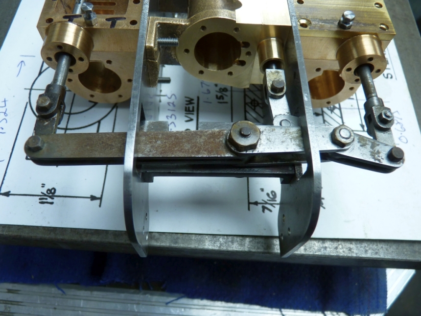
I didn't bother cleaning the levers up at this point just in case I had to replace them in which case it would have been time wasted. I was pleasantly surprised to see that everything seemed to line up ok apart from the righthand end of the long lever so the supporting stretcher was obviously in the right place. The lever proved to be slightly bent so straightening that would solve this alignment problem.
The top of the lever did come very close to the top of the cut out in the LH frame so that needed a bit filing off to give some more clearance.
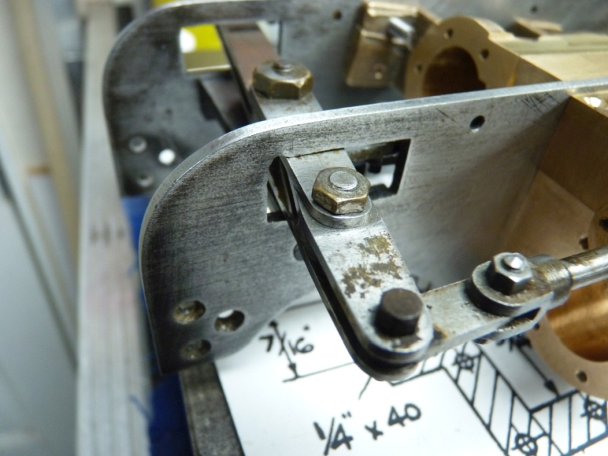
Although the righthand end of the long lever lines up perfectly with the righthand valve spindle, the ends of the short lever do not line up with the lefthand and middle valve spindles. This is because the levers are not the right length. I think LBSC rounded up the dimensions, as he often did, to make the levers easier to make. The difference is small and will have little effect on the valve events.
Out of interest I checked the dimensions of the levers to see if they followed the drawings by holding the levers in the mill vice and measuring the distance apart of the pivot holes using the DRO and a pointed centre in the chuck.
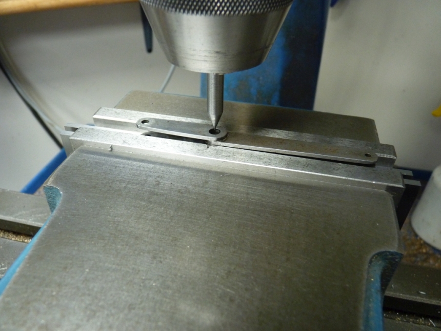
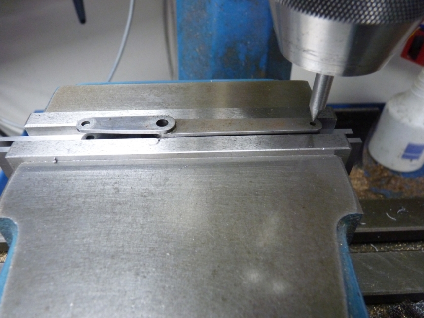
The dimensions for the long lever were within a few thou but the short lever was a bit more 'diverse'! I intended to enlarge the pivot holes in the levers anyway to take 0.125" silver steel pins so that would give me the chance to move the holes to where they should be. The original pins were machined 3/32" Whitworth bolts which didn't give a lot of bearing surface. These pins are quite heavily loaded so I wanted to increase the bearing surface to make them last longer. Incidently, a lot of the original fixings on the loco were Whitworth threads which gives some indication of the age of the loco. 1/16", 3/32" and 1/8" Whitworth bolts were often used in the early days before BA appeared and took over.
The main pivot for the long lever was a bit of a sloppy fit so I machined up a new one from silver steel.
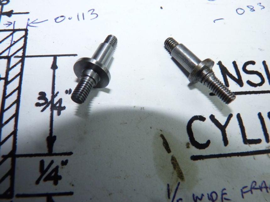
I did consider fitting a bronze bush to the lever instead of the existing plain hole but the lever only rocks backwards and forwards so I decided that it probably wasn't worth it. It will no doubt see me out

The original pivot pin for the short lever was a 0.125 machined bolt which was again a bit of a sloppy fit in both the short lever and the long lever. I drilled and reamed the holes out to 4mm which was the next largest size of silver steel that I had and made a new pin. I made the pin hollow for a bolt to go through it and hold it in place. I then drilled and reamed all the other pivot holes out to 0.125" to take hollow silver steel pins and 'adjusted' the position of the holes in the short lever at the same time.
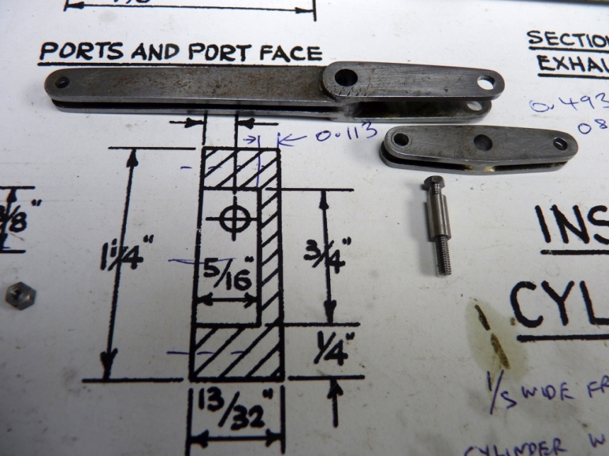
The connecting links that join the levers to the ends of the valve rods were also drilled and reamed to the new size of 0.125"
I've had a problem in the past with fitting these 0.125" silver steel pins. Reaming the holes to 0.125" gives too tight a fit on the pin and in the past I've lapped the holes out with some very fine aluminium oxide powder left from my telescope mirror making days. Just mix it with some oil and it makes a good lapping compound. However, the other day I bought a job lot of small reamers from Ebay and amongst them was a 0.126" reamer which gives the perfect fit and makes the lapping unnecessary now.
That's it for the 2 to 1 levers apart from cleaning them up so let's move onto the slide valves.
Of course, I didn't have any suitable sized material to make the valves from so had to order some 1" diameter gunmetal bar (how much!) that took a couple of days to arrive. That was just big enough to machine the valves out of.
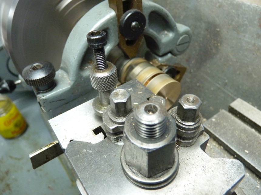
I parted off three suitable blanks in the lathe. The bar was too big to fit through the lathe spindle so I held it in the chuck and used the fixed steady to support the other end. I try and avoid cutting bars up into short lengths if possible as you always seem to finish up with bits left over that you can't hold to do anything with and gunmetal is expensive stuff to waste.


Then to the mill to make them into rectangles.
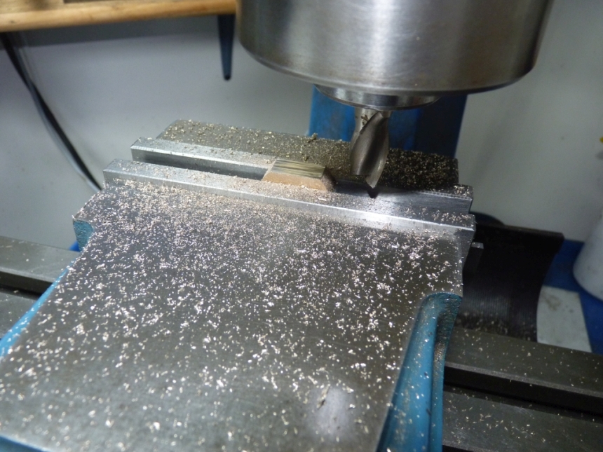
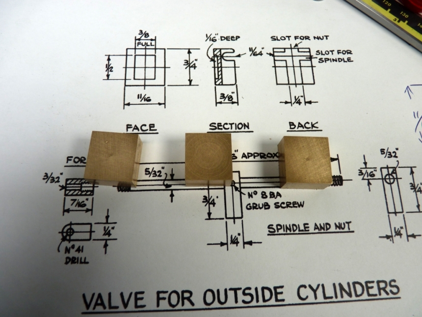
I left the width of the valves 0.025" oversize to allow for finishing after the exhaust cavities had been milled.
I considered milling the slots for the drive nut and the valve spindle next. The slot for the valve spindle can just be flat bottomed but I like to make it rounded. I didn't have a suitable sized ball endmill to just mill it so I drilled a hole through the valve first to give the round bottom.
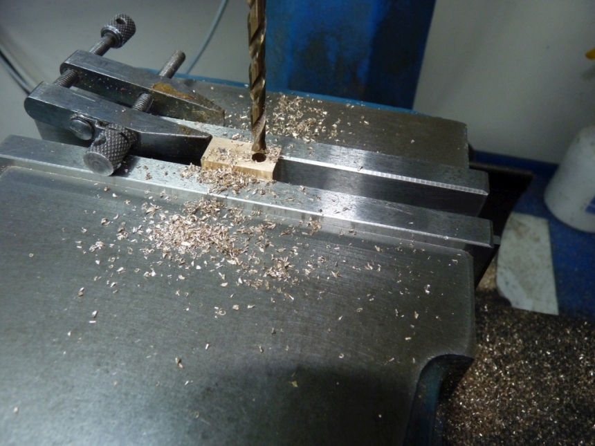
The clamp was used as a stop so I could swap the valves over and only have to set them up for the position of the hole once (Note - I must make a proper vice stop!) I made sure that the bottom of the hole would allow the valve to lift slightly to allow any condensate to escape.
Mr Bozo turned up again as, although I got the hole in the right place, I drilled it through the wrong side of the valve! Much workshop Esperanto and off to make another blank. Then blow me, I nearly did it again! I wasn't having a good day

I remembered later that when I was producing the 3D model I found an error in the position of the valve spindle in the valve. It was out by 0.03125" and the exhaust cavity didn't line up exactly with the ports. I corrected it on my 3D model but then forgot about it and drilled the hole for the valve spindle in the position shown on the drawing. It won't affect anything really, it just means that the cavity is out of line with the ports by 0.03125".
I had a rethink and thought it might be best to machine the exhaust cavity before milling the slots which would leave the valve a bit flimsy to clamp in the vice so the blanks were set up for doing that.
I started the cavity by plunging with an 8mm slotdrill and rough machining the cavity to size followed by a 3mm slot drill to finish to size.
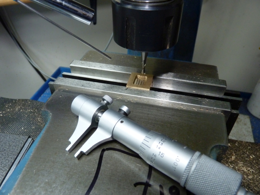
I had picked up that very nice bore micrometer last year for next to nothing and that was ideal for checking the dimensions of the cavity and getting them spot on.
After doing the first one I thought it would be nice to have an air jet to blow away the chips as I was machining. I had a small airbrush compressor so connected a long blunt hyperdermic needle to the end of the hose, taped it to a magnetic stand and voila, an instant air jet.
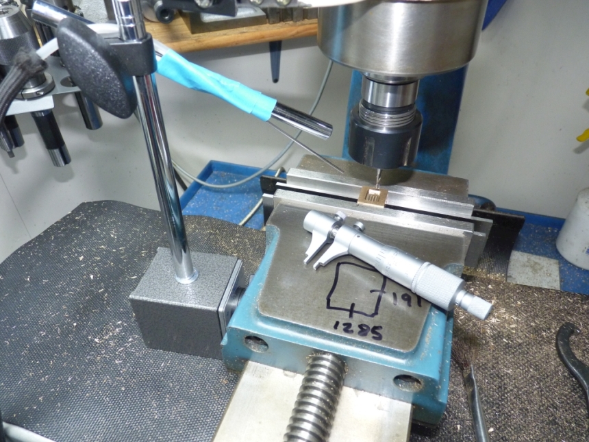
All the cavities turned out fine.
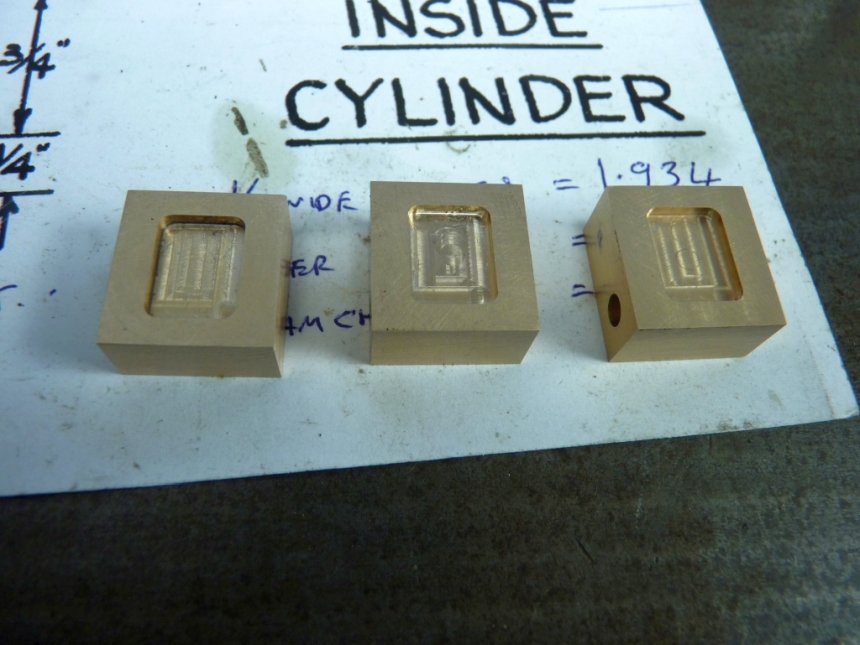
Now I could mill the slots in the outside valves. The inside valve is a bit different and will be done later.
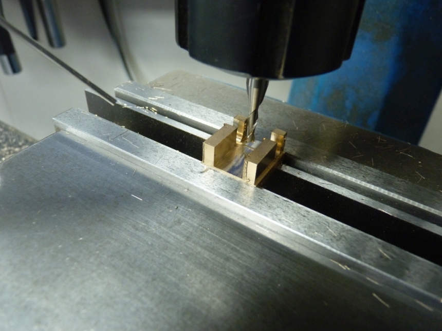
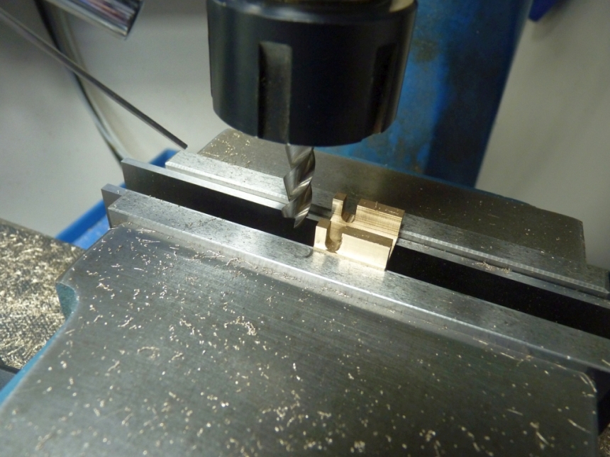
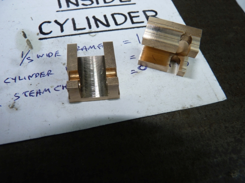
The bottom of the valves are quite thin so the exhaust cavity is only 0.063" deep but that should be ok.
The slot for the drive nut was made quite a bit wider than on the drawings. That's because the drawings show the nuts as being locked to the valve spindle with just one 8BA grub screw. I didn't think that was enough so wanted to fit two 2.5mm stainless grub screws instead. Because of that I had to make the nut wider to fit them in. I also made the nuts taller to give more threads for them to engage in. If you make the nuts the thickness shown on the drawings, the one 8BA grubscrew only has 0.047" of thread engaged which would be hopeless and just strip out.
The drive nuts were milled from 0.375" square brass and simple enough to make. The hole for the valve spindle was drilled and reamed first.
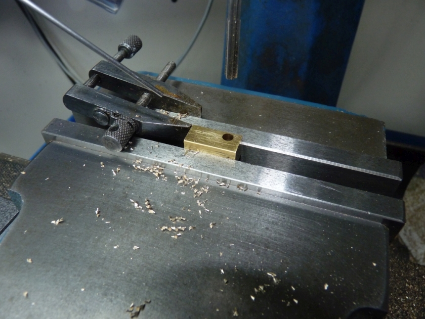
Then the holes were drilled and tapped for the two 2.5mm grub screws.
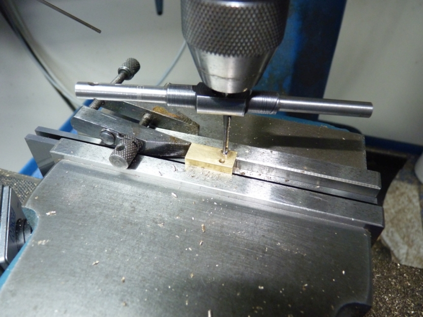
The top of the nut was finally machined to the same height as the valve but leaving a higher part where the tapped holes were, just to give a bit more thread depth.
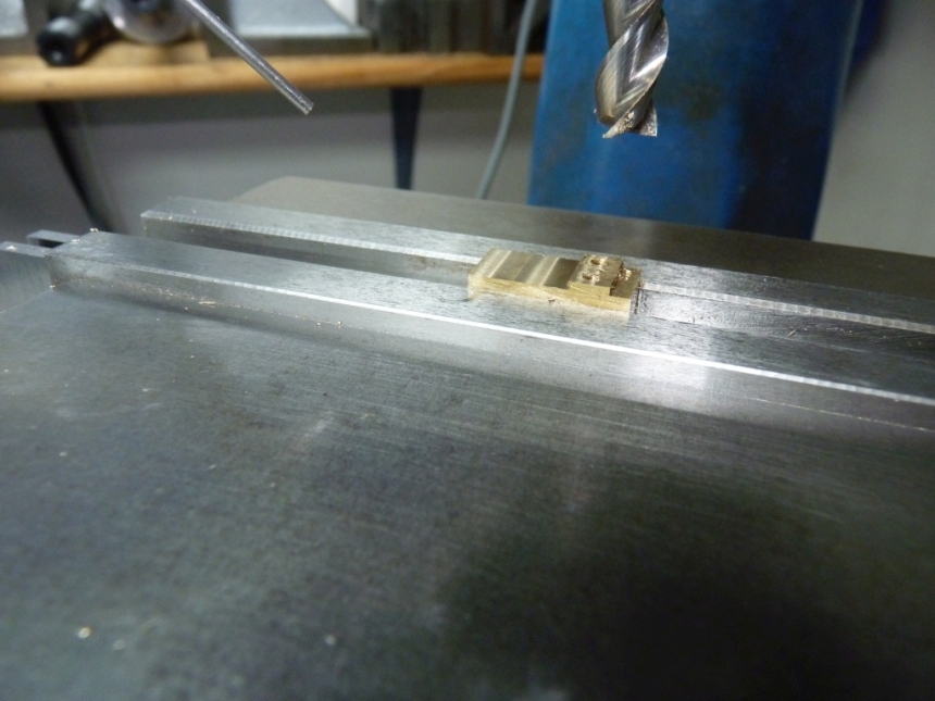
A trial assembly in the steam chest showed everything fitted ok.
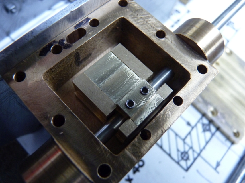
At the moment the grub screws stand up too high but the valve spindle will have a flat machined on the top so that the grub screws don't damage the surface and so they will screw in further.
I think that's enough for tonight. Next time we'll move onto the inside valve.
John